Study on the Mechanical Properties and Bearing Capacity of Ultra-High Performance Concrete Members
Jing Diao1,*, Xingwang Yin1 and Ang Zhang2
1Faculty of Architecture and Engineering, Henan Polytechnic Institute, Nanyang Henan 473000, China
2School of Civil Engineering and Architecture, Zhongyuan Institute of Science and Technology, Zhengzhou Henan 450018, China
E-mail: diaojing2024@163.com
*Corresponding Author
Received 28 May 2024; Accepted 16 July 2024
Abstract
It is used as pier column members in viaducts, urban overpasses and industrial and civil building structures. In practical engineering, short columns or ultra-short columns with relatively small shear span may be formed, and shear failure may become the control condition for components and even structural damage. Under the action of large concentrated load or strong earthquake, the key parts of the high-rise structure and beam bridge system are obviously shear, leading to the serious brittleness and poor ductility of the components, which leads to serious structural continuity collapse, and then brings the loss of life and property. Therefore, it is important to study the shear properties of corrugated concrete members and to study the mechanical properties of components under complex load coupling. TRC comparison, 10 mm incision 100 mm from both ends. The specimen is equipped with 8 HRB400 longitudinal bars of 12 mm diameter along the length direction, the center of the longitudinal bars is 105 mm from the center of the specimen, and the steel content is 1.84%; the longitudinal bars with HPB300 stirrup of 100 along the axial direction, and the steel content of the stirrups is 0.68%. The results show that because the corrugated steel pipe can provide sufficient constraint for the internal core concrete and steel, the corrugated CFCT members have better ductility than the constrained concrete members under the small shear span ratio, which can effectively delay the occurrence of brittle shear failure. The curved shear test study of 12 corrugated concrete filled steel tube specimens was carried out, and the test phenomenon and failure mode of the components under different shear span ratio conditions were compared and analyzed. The study shows that when the shear span ratio is not greater than 0.2, the specimen shear error is obvious, mainly shear failure; when the shear span ratio is between 0.2 and 2.0, the specimen bending shear failure. With the increase of the shear span ratio, the specimen failure form is closer to the bending failure.
Keywords: Corrugated concrete filled with steel tube, pure shear, shear bearing capacity, curved shear correlation, bearing capacity.
1 Introduction
In recent decades, steel-concrete composite structure has been widely used in various ground underground structure, concrete steel tube is a very important and widely used composite structure, have high bearing capacity, good ductility, energy consumption capacity, moderate cost, in the process of practical application by all kinds of high-rise structure, large span structure and underground engineering, which makes the combined structure components of the external working environment gradually extended to industrial atmosphere, adjacent sea waters, etc., saline environment, with the external working environment is more and more complex, components and structure facing the test of corrosion resistance is becoming more and more severe. According to the statistics of the Institute of Oceanology of the Chinese Academy of Sciences [1, 2]. Practical engineering, even in advance to certain anticorrosion treatment, structure in the industrial atmosphere, adjacent sea waters, saline environment, steel is easily exposed to the external environment to corrosion, concrete exposed under the external environment more prone to crack and even fall off, lead to a sharp decline in component bearing capacity, before the service life of structure design has failed and out of work, and even harm to the whole structure. At present, the anti-corrosion measures mainly include anti-corrosion materials and anti-corrosion materials in the components Material, electrochemical protection of the three methods, although these structural anti-corrosion measures can effectively protect the structure from corrosionErostill requires regular maintenance of the structure [3, 4]. For bridge piers and underground buried components in offshore waters and saline-alkali environment, the maintenance process often involves large construction volume, underwater or underground difficulties; for structures in high industrial atmosphere, the maintenance operation usually has poor environment, high risk factor, high difficulty and high cost, which make the structure anticorrosion maintenance a difficult problem to be solved worldwide [5, 6]. Therefore, it is necessary to propose a new type of component that can guarantee the working performance and solve the corrosion maintenance problem in the above environment. From the economy of the building structure, the consumption of steel should be minimized in the design process, so that the thickness of the steel pipe is significantly reduced, so that the thin-wall steel pipe structure arises at the historic moment [7]. However, the thin wall steel pipe member is just too low, which will lead to local buckling of the steel pipe and lose the bearing capacity in advance [8]. Therefore, in order to balance the safety and economy of the structure in engineering construction, improving the stiffness of thin-wall steel pipe has become a research focus in the field of structural engineering at home and abroad. In concrete filled steel tube component, although the steel pipe exists in the form of ring pipe, its main role for the constraint core concrete, do not bear longitudinal load, but in the component by the external load, component deformation, the steel pipe and concrete produced friction, and friction pipe inevitable longitudinal stress, longitudinal stress is the main cause of steel pipe failure, so the influence of longitudinal load on thin-walled steel pipe still cannot be ignored [9]. Therefore, in order to avoid the above problems, the specifications and regulations in the relevant field have required the diameter and thickness ratio of thin-wall steel pipe components [10, 11].
The shape of corrugated steel pipe is similar to the spring, the axial stiffness is low, and the axial load is small. Therefore, even if the corrugated steel pipe in the CFGCST member connects at the node, CSP still plays the role of circumferential constraint core concrete, its force characteristics and the steel pipe constraint concrete [12]. Compared with stainless steel pipe concrete, CFGCST component can significantly reduce the structural cost; considering the maintenance cost during service period, the comprehensive cost of CFGCST may be similar to CFST; compared with TRC, the outer plane stiffness and strength of steel of corrugated steel pipe after cold bending will be greatly improved, making it have high local stability and lateral bearing capacity, so even if the pipe wall is thin, it is not easy to swell in the construction process, which can save the anti-buckling measures and more convenient for construction [13, 14]. In addition, thanks to the advantages of corrugated steel pipe and the combination of corrugated steel pipe and concrete, CFGCST also has the following advantages: good corrosion resistance, free maintenance for 50100 years; corrugated steel pipe has strong constraint effect, high bearing capacity and good ductility [15, 16].
2 Experimental Study on Pure Shear Mechanical Properties of Corrugated Concrete Filled Steel Tube Column
2.1 Bearing Capacity-Span Medium Flexibility
The shape of corrugated steel pipe is similar to the spring, the axial stiffness is low, and the axial load is small. Therefore, even though the corrugated steel pipe in the CFGCST member is connected at the node, as shown in formula (1) and (2), CSP still plays the role of circumferential constraint core concrete, and its force characteristics are similar to those of steel pipe restraint concrete.
| (1) | |
| (2) |
Compared with stainless steel pipe concrete, CFGCST components can significantly reduce the structure cost; considering the maintenance cost during the service period, as shown in formula (3) and (4), the comprehensive cost of CFGCST may be similar to CFST.
| (3) | |
| (4) |
Compared with TRC, the corrugated steel pipe will be greatly improved, as shown in formula (5) and (6), so that it has high local stability and lateral bearing capacity.
| (5) | |
| (6) |
Therefore, even if the pipe wall is thin, it is not easy to swell in the construction process, and the anti-buckling measures can be saved, as shown in formula (7) and (8), which is more convenient for construction. In addition, thanks to the advantages of corrugated steel pipe itself and the combination of corrugated steel pipe and concrete.
| (7) | |
| (8) |
After comprehensive consideration, as shown in Equations (9) and (10), a total of 6 CFGCST specimens with shear span ratio of 0 and 0.1 and 3 TRC specimens with shear span ratio of 0.1 were designed in the pure shear test.
| (9) | |
| (10) |
The pure shear test mainly designed three sets of comparative tests, as shown in formula (11) and (12). The CFGCST member with shear span ratio of 0 and 0.1 were designed. Companalyze the influence of shear span ratio on shear mechanical properties of CFGCST components.
| (11) | |
| (12) |
2.2 Angle-Span Medium Deflection
There are wave crest, trough and transition section, as shown in formula (13) and (14), the stress and strain distribution rules are different from that of flat round steel pipes. The ripple parameters of the corrugated steel pipes will affect the circumferential restraint stress level; under the action of bending moment, the CFGCST constraint effect is not uniform.
| (13) | |
| (14) |
When studying the mechanical properties of CFGCST column under bias load or reciprocating load, if the stress-strain relationship expression defines the material properties of the section, as shown in formula (15) and (16), will overestimate the section bearing capacity and seismic performance of the mechanical properties of CFGCST under the coupling of pure shear and curved shear are blank.
| (15) | |
| (16) |
In practical engineering, the vertical components may be subject to the coupling effect of pressure, bending, shear and torsion load. The shear stress caused by shear force and torque will lead to the change of the main stress direction of the material, thus changing the constraint effect, and then affecting the bearing capacity of the combined components. As shown in formula (17), the mechanical properties of existing CFST components under bending, bending, bending and shear coupling show.
| (17) |
The bending shear bearing capacity is related to the length ratio, constraint effect coefficient, load eccentricity, bending ratio and loading path. Especially for the components with relatively small shear span, as shown in formula (18), the shear force often becomes the control condition for its failure. The brittleness of the components is obvious and the ductility is poor when the shear failure occurs. It is very important to study the shear mechanism of components and limit their shear destruction.
| (18) |
The design and processing of 6 CFGCST components with shear span ratio of 0 and 0.1 and 3 TRC components with 0.1 were completed. As shown in formula (19), the material performance test and pure shear mechanical performance test of single point direct shear loading were completed. The destruction pattern and working mechanism of CFGCST and TRC components are analysed.
| (19) |
Through the monitoring of force sensor and LVDT displacement meter, the bearing capacity of the specimen-the span full curve and the angle-the full span full curve is obtained. As shown in Equation (20), the typical curve characteristics of shear force-displacement of the member under the action of shear force are analyzed.
| (20) |
3 Study on Practical Calculation Method of Shear Bearing Capacity and Curved Shear Correlation
3.1 The Shear Bearing Capacity of Reinforced Concrete Members of Corrugated Steel Pipe is Practical
Under the action of axial pressure, for the circular constraint of CSP for concrete with corrugated steel pipe and the constrained concrete members of steel pipe, due to the good combination of CSP and concrete in CFGCST components, the bearing capacity, peak limit strain and ductility are improved compared with TRC components, and both components are thin-wall members, so this paper selects the TRC test as the comparison test of pure shear and curved shear test of CFGCST test [17, 18]. TRC members with shear span ratio of 0.1 are set to analyse the similarities and differences between shear mechanical properties of CFGCST members and contrast parts under the same shear span ratio; one CFGCST specimen and one TRC specimen with shear span ratio of 0.1 are designed to explore the influence [19, 20]. The first step is to process the flat steel pipe and the corrugated steel pipe according to the design drawings. The flat steel pipe is welded by the hot rolled steel plate after cold bending pipe. After the corrugated steel pipe is hot dip galvanized, the mechanical rolling is formed in the processing plant, and then the bite edge and the cold bending coil pipe [21, 22]. Finally, the special fixture is used to cut according to the test scheme. The second step is to measure the size of the steel pipe and make and locate the steel cage [23]. When determining the actual size of corrugated steel pipe and flat steel pipe, the edge of the paper strip and the part overlapping after winding are marked by winding the hard slip strip outside or covering the steel pipe, measuring the length of the paper strip after deployment and converting it, so as to obtain the measured data of the measured steel pipe [24, 25]. When making and positioning the steel cage, the steel cage into corrugated steel and flat steel pipe. Figure 1 shows the shear bearing capacity of the end plate, the top cage of the steel cage to prevent the torsion from casting the concrete and affecting the test results for the test. Rebar positioning and measured data operation.
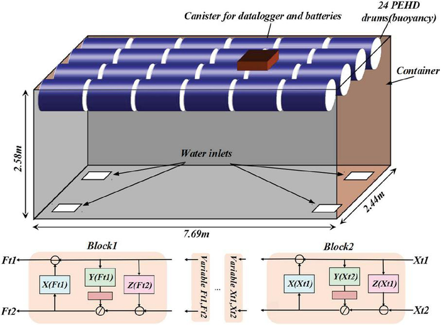
Figure 1 Schematic diagram of the shear bearing capacity of the component.
The third step is the concrete pouring and curing of the concrete. The concrete used in this test is mixed fine aggregate, and the pouring and vibration are layered [26]. The round steel pipe and corrugated steel pipe can be used as formwork for pouring concrete. After the concrete pouring, the top concrete shall be levelled, and a layer of tin foil and waterproof protective film shall be sealed on the top concrete [27, 28]. During the pouring, 150 mm 150 mm 300 mm shall be reserved for curing under the same condition as the specimen. After 28 days of curing, polish the concrete surface on the top of the specimen with angle mill, then flatten the top surface with high strength gypsum, and finally weld the top end plate; for the reserved prismatic test block, the surface concrete shall be polished in the same method to smooth the surface [29, 30]. For TRC comparison parts, a 10 mm ring belt 10 mm 100 mm from the top and bottom, and the concrete compressive strength and elastic modulus shall be measured by the 150 mm 150 mm 300 mm prism standard test block. During the test block, the concrete is wrapped with tin foil and waterproof protective film, and the test block surface shall be leveled with angle grinder. Measurement of mechanical properties, according to the ordinary concrete mechanical properties test method, Table 1 for steel mechanical properties index, take each group of three cubes and three prisms test block measured strength average and elastic modulus, corrugated steel pipe is flat steel strip after hot dip galvanized, in the processing plant, mechanical rolling corrugated shape, then bite edge and cold bending coil forming steel with special folds. Due to the difference in the strength of the crest, wave and trough of the corrugated steel pipe, it is necessary to take the peak, wave and trough when cutting the standard specimen. The corrugated steel pipe mechanical properties test specimen used in this test is cut from the reserved steel plate and steel bar, and is processed and tensile tested according to the standard.
Table 1 Mechanical performance indexes of steel
| Sample | Yield | Ultimate | Modulus of | |
| Material Category | Size | Strength | Strength | Elasticity |
| Galvanized Steel Plain Sheet | t 1.95 | 312 | 435 | 201 |
| Longitudinal Tendon | d1 12 | 465 | 601 | 205 |
| Stirrup | Ds 6 | 303 | 411 | 201 |
Due to the special spiral ripple shape of CSP, the stress is uneven distributed along the thickness and height, so for the loading control of the load progress and the load-displacement relationship curve, determine the displacement of the specimen, measure the displacement capacity of the corrugated steel pipe during the test process, and monitor the scheme arrangement. From the arrangement of the displacement meter, A total of 5 displacement meters are arranged, From the arrangement of the strain flowers, 5 groups of strain flowers along the circumferential surface of shear, The angle between each group of strain flowers and the central line of the specimen is 45, Due to the different stress characteristics of crest, middle and trough in a corrugated section of corrugated steel pipe, Therefore, it is necessary to arrange strain flowers in the same direction at the crest, middle and trough of a corrugated section of the shear zone, Strain data were collected using a DH3816 static collector, Acquisition across median displacement data using the Tester acquisition system, The force data is collected using a force sensor.
3.2 Bending and Shear Correlation of Reinforced Concrete Members of Corrugated Steel Pipe
From the perspective of the arrangement of strain flowers, the center of the test in the wave peak, wave and trough are arranged in the same direction. During the test process, the DH3816 static acquisition instrument is used to collect strain data, collecting the sample span displacement data, and the force sensor is used to collect the force data. Section, The corrugated steel pipe in the vicinity of the hoop is gradually pressed tightly, The corrugated steel pipes began to be flattened, And accompanied by an intermittent slight “crackling” sound; Continuing loading to the estimated limit load, The component moves down across the middle section, The corrugated steel pipe appears slightly bulging across the shear area, A slight tear occurred at the bite site, The components showed a significant shear deformation, The corrugated steel pipe is torn and accompanied by a small amount of concrete powder overflow, The corrugated steel pipe tear issued a “crackling” sound more and more dense, The crack develops along the edge of the holding hoop, Finally, the components bang, The test is finished when the bearing capacity of the member decreases. Photos of TRC specimen T-0.1-1 before loading, early loading and late loading. Figure 2 shows the destruction pattern of specimen T0.1-1, For TRC pure test T-0.1-1, As can be observed during the experiment, During the initial elastic phase of the loading, Can see that the loading point is slowly decreasing, The hoop and the external corrugated steel pipe are gradually pressed tightly, With the shear marks present, However, the overall TRC specimen has no obvious deformation; After the component enters the elastoplastic phase, Sslight slight saappeared in the steel pipe near the hoop, The g appeared earlier than CFGCST specimens, And accompanied by an intermittent slight “crackling” sound; When loaded to the estimated limit load, The TRC specimen rapidly moves down across the middle section, Significant shear deformation across shear regions, A “bang” sound when the steel pipe tears, The crack develops rapidly along the edge of the hoop, The test is finished when the bearing capacity of the member decreases.
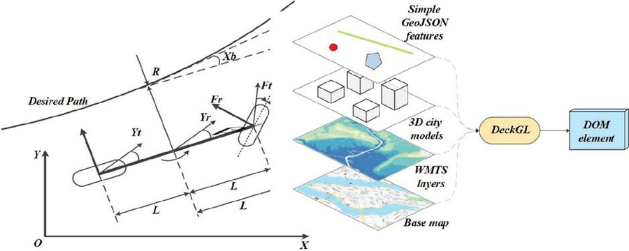
Figure 2 Destruction pattern of specimen T0.1-1.
The corrugated steel pipe in contact with the hoop area was almost completely flattened, the corrugated steel pipe in the straight shear section was cut open, and the slight tearing and bulging of the bite appeared. During the test, the bearing capacity of the corrugated steel pipe did not drop when the pipe was cut. A small amount of concrete powder flows out of the pipe, but no concrete falls. After stripping the pipe, the corrugated steel pipe has good constraint effect. If you carefully observe the concrete, you can see several short shear peaks, which extend along the shear column, the crack and the cutting angle is between 30 and 45, and the concrete has obvious shear pressure failure. Breaking open the concrete can see that the phenomenon of the internal stirrup is not obvious, and the longitudinal reinforcement produces obvious shear dislocation, which proves that for CFGCST components by pure shear, because of the existence of good bolt effect between the longitudinal reinforcement and concrete, the longitudinal reinforcement provides most of the shear. Figure 3 shows the bearing capacity of pure shear specimen-span deflection curve and the failure pattern of CFGCST specimen C-0.1-1. It can be observed that the CFGCST specimen shows obvious shear deformation characteristics, the overall shear dislocation is obvious, the corrugated steel pipe in contact with the hoop area is flattened, and the corrugated steel pipe in the straight shear section is cut open. In the process of stripping, there is a small amount of concrete powder flowing out, and there is no phenomenon of concrete block falling. After stripping, the pipe, it can be observed that the concrete shear deformation is obvious. The shear inclined cracks develop along the shear surface, but the shear inclined crack is not obvious.
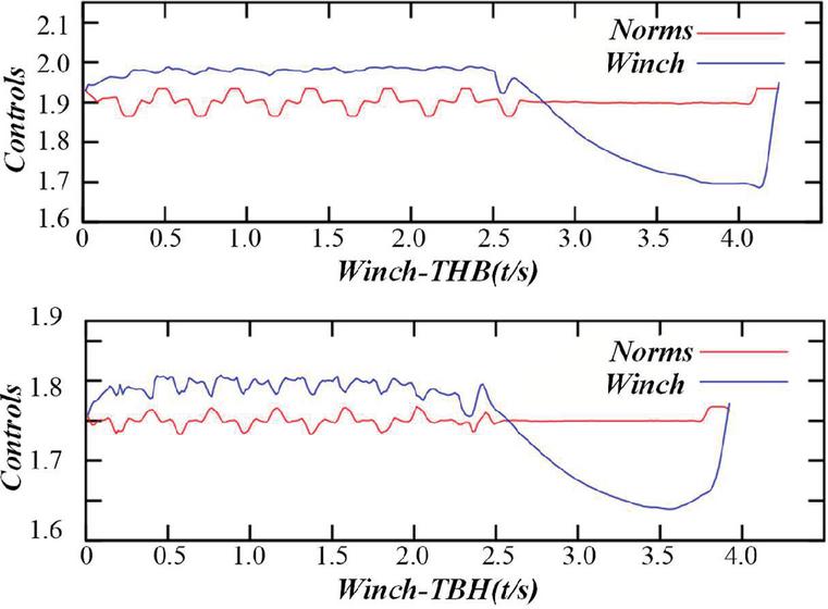
Figure 3 Bearing capacity of pure shear test piece-span medium deflection curve.
The struction form of concrete specimen T-0.1-1. It can be seen that the shear deformation characteristics of TRC specimens are obvious, the overall shear fault is obvious, the steel pipe is cut out, the inner area, and the cracks extend along the shear surface; during the stripping process, a small number of concrete blocks fall, and the concrete inclined crack is obvious. For the provoked plate test, the test phenomenon is the same as the end plate test, and no concrete is obviously squeezed out. Comparing the experimental process and destruction morphology of CFGCST and TRC components is not difficult to find, CFGCST The overall performance of the components is good, This is due to the presence of corrugated steel tubes, When subjected to the shear force, The corrugated steel pipe can provide a part of the shear bearing capacity for the specimen due to its special fold, And the constraint effect of corrugated steel pipe on concrete can improve the shear resistance of concrete, Can also make the internal concrete and steel reinforcement better synergy, It can also improve the ductility of the components; Although the outer steel pipe of the TRC member can also provide constraints for the inner concrete of the member, However, its constraint effect is obviously lower than the constraint of corrugated steel pipe on the internal concrete.
4 Study on the Mechanical Properties and Bearing Capacity of Ultra-high Performance Concrete Members
Comparing the experimental process and destruction morphology of CFGCST and TRC components is not difficult to find, CFGCST The overall performance of the components is good, This is due to the presence of corrugated steel tubes, When subjected to the shear force, The corrugated steel pipe can provide a part of the shear bearing capacity for the specimen due to its special fold, And the constraint effect of corrugated steel pipe on concrete can improve the shear resistance of concrete, Can also make the internal concrete and steel reinforcement better synergy, It can also improve the ductility of the components; Although the outer steel pipe of the TRC member can also provide constraints for the inner concrete of the member. Table 2 shows the corresponding to the shear bearing capacity of pure shear test and the deflection of the span. Preparation before loading Before the loading process, the overall leveling work and wiring work are required.
Table 2 Corresponding to shear bearing capacity and midspan deflection of pure shear specimens
| Sample Type | Py | Xt(Mm) | Vy | Destructional Forms |
| C-Ps | 711.8 | 6.9 | 355.9 | Pure Shear |
| C-0.1 | 665.7 | 8.6 | 332.9 | Pure Shear |
| T-0.1 | 755.4 | 7.5 | 377.7 | Pure Shear |
Prepare before loading, and perform overall leveling and wiring work before loading. Figure 4 is the monitoring scheme of curved shear test. This test needs to record the following data, strain data: the load-strain curve of bolts and concrete can be obtained through the prearranged strain sheet. Maximum bearing capacity: the maximum bearing capacity occurring during the specimen loading process. Average shear bearing capacity of the bolt: the maximum bearing capacity is on average to the bearing capacity of each bolt. Maximum displacement: the displacement corresponding to the ultimate bearing capacity. Relative slip: the relative displacement of the steel beam and the bolt.
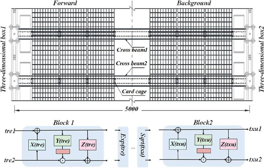
Figure 4 Monitoring scheme of curved shear test.
Destruction form: the expected damage form includes bolt root shear, bolt shear deformation, and concrete failure. Mechanism sand is crushed and made by machine on rocks with particle size below 4.75 mm. The concrete configured with mechanical sand has various physical indicators similar to the concrete configured with natural sand, and the stone powder contained in mechanical sand will improve the workability of concrete, and is a good substitute for natural sand. At the same time, the production of mechanical sand can be used to reduce transportation costs; and according to customer needs, controllable and adjustable. According to the centennial construction network statistics, the price of mechanical sand has been lower than that of natural sand. So mechanical sand can be a perfect substitute for natural sand. At present, many areas have issued relevant policies to encourage the use of mechanism sand configuration concrete. Self-compacting concrete is a kind of concrete with high fluidity, which will not segregation and bleeding phenomenon occur in the pouring process, and can fill the formwork and wrap the steel bar without relying on artificial vibration. With its unique Self-compacting, self-compacting concrete is used in a variety of special projects, such as environmental factors cannot be vibration, dense reinforcement components. Figure 5 shows the corner of pure shear test-span deflection curve.

Figure 5 Angle of pure shear specimen-span medium deflection curve.
Steel-concrete composite component is composed of steel and concrete, two different properties of materials through the connection components. It has good compression ability and tensile ability, and is often used in high-rise buildings, multi-storey industrial plants, highway and railway Bridges, long-span Bridges, etc. It is also one of the development trends of mechanical sand to apply self-compacting concrete to steel-concrete composite components. Subsequently, the load of the specimen increases slowly, but the slip growth rate is significantly larger, indicating that the specimen is about to enter the destruction stage. At this time, in order to ensure the safety of the test personnel, the development of cracks is not observed. The root shear failure of the specimen. The destruction of the concrete is not serious, it can be seen that the concrete will still appear cracks, but most of them are concentrated in the concrete near the bolt hole around, and there will be local crushing damage. The bolt connections have been damaged. As can be seen from the damage of the welding between the steel beam and the bolt and the root of the bolt buried in concrete, there is a slight bending deformation before the bolt failure.
From the concrete load-strain curve diagram, it can be seen that in the loading process, most of the time the concrete strain grows slowly and the value is small, and only some curves change dramatically in the damage stage. Most of these curves are numbered curves ending with S, that is, the concrete strain curve near the bolt side, which is also in line with the actual concrete failure phenomenon, because the concrete near the bolt will produce cracks in the loading process, which leads to drastic changes in the concrete strain. And the serial curve ending with F, that is, the concrete strain curve away from the bolt, is small and changes slowly from the beginning of loading to the end of loading. From the phenomenon of concrete damage, the concrete far away from the side of the bolt really has no obvious damage characteristics. During the loading process, because the bending changes exist before the bolt is broken. If the bolt strain changes, the strain gauge damage should be caused by the bending deformation of the bolt. At the same time, by comparing the curve number 1357 in the overall strain curve, namely the first layer bolt strain curve, and the curve and number 2468, namely the second layer bolt strain curve, it can be seen that the first layer and the second layer bolt by strain, combined with the concrete slab, near the concrete hole is roughly the same stress, the bearing capacity is similar. This can also verify the Samy Guezouli scholars proposed that the number of bolt layers from one layer to two layers will not produce a group nail effect. The force of the bolt connector in the combined member is closely related to the concrete, and the stress state is more complex, which can be regarded as an “elastic foundation beam”. Because the relative strength of bolt and concrete is different, there are generally two failure modes. One is the concrete damage, which usually occurs when the concrete strength is relatively small. The other is the bolt shear failure, which usually occurs when the bolt strength is relatively high, which is also the failure mode of this test. In the mode of bolt shear failure, when the load is just applied to the steel beam, the specimen is in the elastic stage, and the shear force of the bolt is mainly transmitted through the concrete around the bolt, which causes local compressive stress in the concrete near the bolt, which leads to the collapse damage of the concrete under the hole of the bolt. As the load continues to increase, the root of the bolt is deformed under the influence of stress, which has a rotation trend, while the concrete near the head of the bolt will cause constraints to prevent the rotation of the bolt, which leads to the bending deformation of the root of the bolt. The final bolt is cut to reach the maximum bearing capacity. At this time, the higher the concrete strength, the stronger the constraint of the concrete near the bolt, which indirectly improves the shear ability of the bolt.
5 Experimental Analysis
The load-sliding of the specimen with different longitudinal spacing of the bolts can be simply seen that the longitudinal spacing of the bolt has a certain impact on the load-sliding curve of the bolt, the larger the spacing. Figure 6 is the deflection curve of the curved shear specimen-span, and the higher the maximum bearing capacity of the specimen. In the same way, the influence of longitudinal spacing of bolts on shear bearing capacity and shear stiffness can be analysed.
Figure 6 Bearing capacity of curved shear specimen-mid-span deflection curve.
The stress state of the bolt connector has been described in the previous section. We know that the shear force of the bolt is mainly transmitted by concrete, so that the concrete near the bolt will produce local compressive stress. The concrete damage is more serious. Figure 7 Angle-span deflection curve, which will gradually spread along the load application direction and transfer to the concrete near the next layer of bolts.
Figure 7 Angle-span medium deflection curve.
If the spacing between the two layers of bolts is small, during the transmission process, Figure 8 shows the analysis of the results of pure shear and curved shear tests. The local compressive stress of the concrete near the bottom bolt transmitted by the top bolt concrete is easy to lead to concrete damage. In this test, this was common for specimens with 80 spacing, but this was not obvious for specimens with 155 spacing.
Figure 8 Analysis of pure shear and curved shear test results.
It is mentioned that concrete will have a constraint effect on the bolt, inhibit the rotation trend of the bolt, and indirectly improve the shear capacity of the bolt. In the concrete under the state of damage, the constraint capacity decreases. Figure 9 shows the comparison of the shear bearing capacity under different shear span ratios, resulting in the decrease of the shear bearing capacity of the bolt. Therefore, the increase of the spacing between the bolts will increase the shear capacity of the bolts.
Figure 9 Comparison of shear bearing capacity and specification under different shear span ratio.
And spacing between nailing-on-nailing shear stiffness, is the concrete local pressure stress transfer to the next layer of bolt, often occur in the late loading, Figure 10 for corrugated concrete filled steel tube curved shear correlation curve, bolt already entered the plastic stage and even damage stage, so the early loading of nailing shear stiffness does not affect.
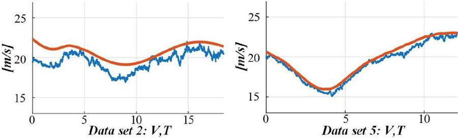
Figure 10 Curshear correlation curve of corrugated concrete filled steel pipe.
According to the comparative results, the calculation formula stipulates that the applicable condition is the height of the bolt, which will improve the shear bearing capacity of the bolt, so the calculation result of the formula is obviously too large. Figure 11 shows the curved shear correlation curve and the verification curve.
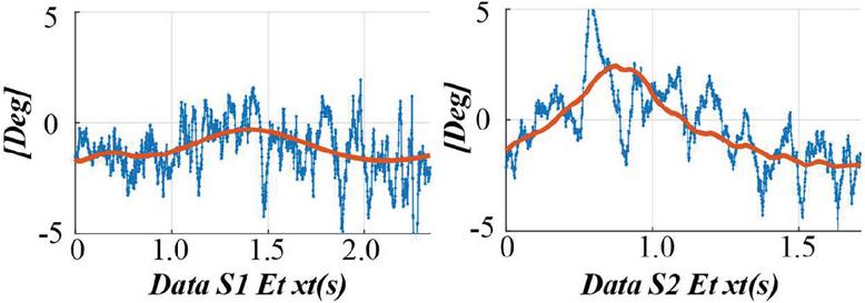
Figure 11 Curved-shear correlation curve and verification curve.
6 Conclusion
In the test process, it can be observed that the CFGCST component is mainly deformed at the contact between the crest and the hoop, and the corrugated steel pipe is almost pressed before the whole section enters the shear work; and the CFGCST structure, the corrugated steel pipe plays a good constraint effect on the internal concrete and internal steel bar, so that the corrugated steel, internal concrete and steel bar can work together. It can be obtained from the curve of bearing capacity-span deflection, the full curve of bearing capacity-span deflection of CFGCST member can be divided into three stress stages: elasticity, elastic-plastic and reinforcement, while the TRC member has no strengthening stage, and the CFGCST member is reduced by 6%. The calculated value of shear bearing capacity is less than the test value. According to the figure, when the concrete strength grade of the specimen is C45, C55 and C65, the corresponding average shear bearing capacity is 63.31 kN, 68.83 kN, 72.84 kN respectively.
Although the improvement of concrete strength grade will increase the average shear capacity of bolts, the increase will be decreased. Based on the shear mechanism of CFGCST member and the calculation principle of the standard shear bearing capacity of various countries. The formula is composed of the shear bearing capacity of concrete, longitudinal steel bar and corrugated steel pipe. Comparing the pure shear test results with the calculated value, the results prove that the error of the formula is less than 10%, and the calculated value of the shear bearing capacity is less than the test value, which proves that the formula is too safe for the shear bearing capacity of components. Based on the formula of CFGCST members and the bending bearing capacity of CFGCST members, the correlation curve of CFGCST members is obtained, and the verification curve of the curve is within 10%, proving that the correlation curve can be used as the correlation curve of CFGCST components.
References
[1] Chu, H., Gao, L., Qin, J., Jiang, J., and Wang, D. (2022). Mechanical properties and microstructure of ultra-high-performance concrete with high elastic modulus. Construction and Building Materials, 335, 127385.
[2] Yang, J., Chen, R., Zhang, Z., Zou, Y., Zhou, J., and Xia, J. (2023). Experimental study on the ultimate bearing capacity of damaged RC arches strengthened with ultra-high performance concrete. Engineering Structures, 279, 115611.
[3] Wang, D., Ju, Y., Zheng, W., and Shen, H. (2018). Seismic behavior and shear bearing capacity of ultra-high performance fiber-reinforced concrete (UHPFRC) beam-column joints. Applied Sciences, 8(5), 810.
[4] Banerji, S., and Kodur, V. (2022). Effect of temperature on mechanical properties of ultra-high performance concrete. Fire and Materials, 46(1), 287–301.
[5] He, S., Deng, Z., and Yao, J. (2020). Seismic behavior of ultra-high performance concrete long columns reinforced with high-strength steel. Journal of Building Engineering, 32, 101740.
[6] Raheem, A. H. A., Mahdy, M., and Mashaly, A. A. (2019). Mechanical and fracture mechanics properties of ultra-high-performance concrete. Construction and Building Materials, 213, 561–566.
[7] Fang, H., Gu, M., Zhang, S., Jiang, H., Fang, Z., and Hu, J. (2022). Effects of Steel Fiber and Specimen Geometric Dimensions on the Mechanical Properties of Ultra-High-Performance Concrete. Materials, 15(9), 3027.
[8] Pourbaba, M., Joghataie, A., and Mirmiran, A. (2018). Shear behavior of ultra-high performance concrete. Construction and Building Materials, 183, 554–564.
[9] Lei, D. Y., Guo, L. P., Li, Y., Zheng, Z., Liu, J. P., Li, S. C., … and Zhong, B. M. (2021). The investigating on mechanical properties of ultra-high strength and ultra-high ductility cementitious composites (UHS-UHDCC). Journal of Building Engineering, 43, 102486.
[10] Ragalwar, K., Heard, W. F., Williams, B. A., Kumar, D., and Ranade, R. (2020). On enhancing the mechanical behavior of ultra-high performance concrete through multi-scale fiber reinforcement. Cement and Concrete Composites, 105, 103422.
[11] Zhang, D., Liu, Y., and Tan, K. H. (2021). Spalling resistance and mechanical properties of strain-hardening ultra-high performance concrete at elevated temperature. Construction and Building Materials, 266, 120961.
[12] Hasnat, A., and Ghafoori, N. (2021). Properties of ultra-high performance concrete using optimization of traditional aggregates and pozzolans. Construction and Building Materials, 299, 123907.
[13] Haile, B. F., Jin, D. W., Yang, B., Park, S., and Lee, H. K. (2019). Multi-level homogenization for the prediction of the mechanical properties of ultra-high-performance concrete. Construction and Building Materials, 229, 116797.
[14] Meng, L., Zhang, C., Wei, J., Li, L., Liu, J., Wang, S., and Ding, Y. (2023). Mechanical properties and microstructure of ultra-high strength concrete with lightweight aggregate. Case Studies in Construction Materials, 18, e01745.
[15] Ahmad, S., Bahij, S., Al-Osta, M. A., Adekunle, S. K., and Al-Dulaijan, S. U. (2019). Shear behavior of ultra-high-performance concrete beams reinforced with high-strength steel bars. ACI Structural Journal, 116(4), 3–14.
[16] Zhang, Y., Zhu, P., Wang, X., and Wu, J. (2020). Shear properties of the interface between ultra-high performance concrete and normal strength concrete. Construction and Building Materials, 248, 118455.
[17] Liu, C., Zhang, Y., Yao, Y., and Huang, Y. (2019). Calculation method for flexural capacity of high strain-hardening ultra-high performance concrete T-beams. Structural Concrete, 20(1), 405–419.
[18] Zhang, Y., Li, X., Zhu, Y., and Shao, X. (2020). Experimental study on flexural behavior of damaged reinforced concrete (RC) beam strengthened by toughness-improved ultra-high performance concrete (UHPC) layer. Composites Part B: Engineering, 186, 107834.
[19] Wang, Z., Yan, J., Lin, Y., Fan, F., and Yang, Y. (2020). Mechanical properties of steel-UHPC-steel slabs under concentrated loads considering composite action. Engineering Structures, 222, 111095.
[20] Cao, Q., Nawaz, U., Jiang, X., Zhang, L., and Ansari, W. S. (2022). Effect of air-cooled blast furnace slag aggregate on mechanical properties of ultra-high-performance concrete. Case Studies in Construction Materials, 16, e01027.
[21] Zhou, M., Lu, W., Song, J., and Lee, G. C. (2018). Application of ultra-high performance concrete in bridge engineering. Construction and Building Materials, 186, 1256–1267.
[22] Hu, R., Fang, Z., Shi, C., Benmokrane, B., and Su, J. (2021). A review on seismic behavior of ultra-high performance concrete members. Advances in Structural Engineering, 24(5), 1054–1069.
[23] Mishra, O., and Singh, S. P. (2019). An overview of microstructural and material properties of ultra-high-performance concrete. Journal of Sustainable Cement-Based Materials, 8(2), 97–143.
[24] Cogurcu, M. T. (2022). Investigation of mechanical properties of red pine needle fiber reinforced self-compacting ultra high performance concrete. Case Studies in Construction Materials, 16, e00970.
[25] Yang, J., Peng, G. F., Shui, G. S., and Zhang, G. (2019). Mechanical properties and anti-spalling behavior of ultra-high performance concrete with recycled and industrial steel fibers. Materials, 12(5), 783.
[26] Wu, Z., Khayat, K. H., and Shi, C. (2019). Changes in rheology and mechanical properties of ultra-high performance concrete with silica fume content. Cement and Concrete Research, 123, 105786.
[27] Shafieifar, M., Farzad, M., and Azizinamini, A. (2018). A comparison of existing analytical methods to predict the flexural capacity of Ultra High Performance Concrete (UHPC) beams. Construction and Building Materials, 172, 10–18.
[28] Bian, C., and Wang, J. Y. (2019). Mechanical and damage mechanisms of reinforced ultra high performance concrete under tensile loading. Construction and Building Materials, 226, 259–279.
[29] Yao, Y., Silva, F. A., Butler, M., Mechtcherine, V., and Mobasher, B. (2021). Tensile and flexural behavior of ultra-high performance concrete (UHPC) under impact loading. International Journal of Impact Engineering, 153, 103866.
[30] Dong, S., Wang, Y., Ashour, A., Han, B., and Ou, J. (2020). Nano/micro-structures and mechanical properties of ultra-high performance concrete incorporating graphene with different lateral sizes. Composites Part A: Applied Science and Manufacturing, 137, 106011.
Biographies

Jing Diao received her bachelor’s degree in management from Henan University of Finance and Politics in 2006, and her master’s degree in engineering from Huazhong University of Science and Technology in 2014. Currently, she is a lecturer in the School of Construction Engineering of Henan Industrial Vocational and Technical College. Her research areas and directions include construction materials, construction engineering, engineering management and project management.

Xingwang Yin received the Bachelor’s degree in Architecture from Guangzhou University in 2015 and the Master’s degree in Engineering from Nanyang Normal College in 2019. Currently, she is an assistant professor in the School of Architectural Engineering, Henan Institute of Industrial Vocational Technology. His research fields and directions are construction materials, construction engineering, and architectural design.

Ang Zhang received the bachelor’s degree in engineering from Zhengzhou University in 2010, the master’s degree in engineering from Taiyuan University of Technology in 2014. He is currently a full-time teacher at the School of Civil Engineering and Architecture, Zhongyuan Institute of Science and Technology. His research areas and directions include engineering mechanics and building materials.
European Journal of Computational Mechanics, Vol. 33_4, 411–434.
doi: 10.13052/ejcm2642-2085.3344
© 2024 River Publishers