Static Analysis and Optimization Design of Complex Building Structure Based on Finite Element Method
Huaiping Peng* and Zhongyuan Li
School of Civil Engineering and Architecture, Zhengzhou Urban Construction Vocational College, Zhengzhou, 450052, China
E-mail: 13683773588@163.com
*Corresponding Author
Received 20 August 2024; Accepted 23 October 2024
Abstract
This paper employs a three-dimensional nonlinear finite element method to analyze settlement and deformation during construction. By considering the interaction between the superstructure, foundation, and subgrade, the method reveals both the magnitude of settlement and the distribution of uneven settlement across the structure. This information is used to adjust the foundation design or implement structural measures to ensure uniform settlement, thereby preventing damage caused by differential settlement. In terms of absolute settlement values, the Mohr-Coulomb model predicts the largest settlement, with a maximum value of approximately 11.7 cm. The linear elastic model calculates the smallest settlement, with a maximum value of around 4.5 cm. The Duncan-Chang model offers an intermediate prediction, with a maximum settlement value of about 8.9 cm. Utilizing the ABAQUS finite element software, a 3D model of a natural foundation strip for a three-story masonry structure was developed. The Duncan-Chang nonlinear elasticity model, which effectively describes the behavior of hardening soil, was applied within the software platform to conduct a detailed numerical simulation. At the same time, the paper assumes that the foundation soil is considered the linear elastic model and the Moore-Coulomb ideal elastic-plastic model is compared with the internal force of the superstructure under different foundation models obtained. According to the maximum principal stress analysis, the areas where the wall may be damaged are received, and the measures to reduce the uneven settlement are proposed.
Keywords: 3D nonlinear finite element method, common action, static analysis, frame structure.
1 Introduction
In view of the limitations of previous calculation means, in the analysis of high-rise building structure, do not consider the primary method or conventional basic design method to design the calculation infrastructure structure [1]. Obviously, these two design methods are not consistent with the fact that the superstructure, the foundation and the foundation are a whole [2]. Especially for high-rise buildings, ignore the stiffness contribution of the results and the actual effect of the whole system results sometimes far, even get incorrect result, may lead to large uneven settlement, so that the superstructure produce larger secondary stress, is a lot of house cracks even one of the main reasons to endanger safety [3, 4]. The analysis and study of the interaction and joint action of different media in geotechnical engineering can be divided into three levels: the interaction between the microscopic levels of geotechnical materials; the interaction between soil and composite soil or soil and reinforced materials; and the interaction between foundation and building. In this paper, the main study of the upper and lower structures works together, namely the third level [5, 6].
Taking the superstructure, foundation and foundation as a whole, these three should not only meet the static balance conditions, but also meet the deformation coordination conditions between them in the contact parts, and then analyze the internal force and deformation of these three [7, 8]. The interaction problem of foundation-foundation-superstructure is basically divided into two aspects. According to the different load conditions, the joint action of superstructure, foundation and foundation is divided into interaction under static load and interaction under dynamic load. The joint action of static force is the joint action of the superstructure under the static load, such as the action of the building by its own gravity [9, 10]. Research on this problem, and the research results in this field mainly focus on the contact force of the three in the contact surface. The study of dynamic interaction aims to reveal the response law of superstructure, foundation and foundation to dynamic excitation under the action of dynamic load. At present, it is widely used in large power machinery foundation, nuclear reactors, Marine platforms, high-rise buildings, Bridges, DAMS and other fields [11, 12]. In essence, considering the joint action of the three dynamics is most in line with the characteristics of the structure under the dynamic action. Therefore, in order to have a more correct understanding of the dynamic response of the building under the action of the dynamic load, the study of the joint action of the dynamic action is essential and the three factors under the static load. Any research topic has its value. To solve this valuable problem, we must first have a scientific theory as the basis [13, 14].
Since the second half of the 19th century, The study on the contact problem of two different types of media under various loads provides a theoretical preparation for the development of this topic: the contact problem of elastomer under the normal load, The stress distribution on the contact surface is calculated and tested; For the first time, the stress and strain problem of homogeneous isotropic elastic half-space under the action of a smooth rigid body are proposed; Mortont and Close according to the solution of Hertz, The stress in an isotropic elastic half-space concave under a smooth sphere is calculated by a harmonic function; On the basis of the Boussinesq solution, To obtain some numerical results in the case of flat bottom and conical rigid body; The effect of friction at the interface and suggest a general principle of elastic contacts between two semi-infinite elastomers [15, 16]. Since then, these theories have been constantly improved, and the theoretical research of the superstructure, foundation and foundation has been continuously promoted. The combined effect of multi-layer frame structures on separate basis is studied [17, 18]. A method for calculating foundation settlement, contact stress and bending moment by considering the stiffness of the superstructure is presented. During this period, the analysis of the joint action presents two characteristics: due to the limitations of the calculation tools, it is generally simplified to the plane problem, and the foundation is envisaged as a simple elastic model, and the contribution of the superstructure to the foundation intuitively and explicitly considers the foundation stiffness, so as to calculate the internal force and deformation of the foundation [19].
2 Analysis Method of Superstructure-Foundation- Foundation Interaction System
2.1 Line of the Elastic Foundation Model
The beam shear force is positively symmetrically distributed, but if the positive is negative. That is, at the junction of the second layer beam and the transverse column. For the same Y value, the second layer beam has the greatest shear force effect. As shown in formula (1) and (2), it is known that the shear force of the middle beam is greater than that of the edge beam. It is revealed that the foundation, foundation and superstructure have undergone uneven settlement, large in the middle and small on both sides, disc-shaped, in particular, the soil settlement of the foundation below the foundation is radial.
| (1) | |
| (2) |
The uneven settlement of the whole structure occurs. Frame structure is sensitive to uneven settlement, as formulas (3), (4), namely uneven settlement on the superstructure, therefore because of the superstructure settlement difference, produce secondary stress in the superstructure, the external load to meet the basic balance conditions of normal stress and shear stress called primary stress, and the adjacent structure constraints or the normal stress and shear stress is called secondary stress.
| (3) | |
| (4) |
Compared with the linear elasticity model of the foundation model, the floor MISES level is relatively reduced, and the relative difference value of MISES stress is also reduced. As shown in Equations (5) and (6), using the Moore-Coulomb model can make the superstructure force relatively uniform.
| (5) | |
| (6) |
The bending moment distribution of each column along the Y axis direction and X axis direction is compared with the bending moment value under the linear elastic model. As shown in Equations (7) and (8), but from the quantitative analysis, it shows that the bending moment is smaller under the Moore-Coulomb model than the results of the linear elastic model. Throughout the corresponding bending moment output results of other columns and beams, it is still known that the distribution law and the distribution law under the linear elasticity model are consistent.
| (7) | |
| (8) |
According to the structural mechanics knowledge, the two ends of settlement difference, such as formulas (9), (10), the greater the moment value, so the uneven settlement difference under the Moore-Coulomb model is less than the column foundation under the elastic foundation model. The distribution pattern is still the same, However, according to the analysis, the shear value at the same position is relatively reduced, that is, the shear level is relatively reduced, and at the same time, the shear difference is also relatively reduced. The reason is that the relative settlement difference between the two ends of the beam is reduced.
| (9) | |
| (10) |
2.2 Elastic-Plastic Foundation Model
From the structural mechanical knowledge, the internal force and displacement of the symmetric structure are under positive symmetric load. Because the frame structure model is symmetric, as shown in Equations (11) and (12), and the load is positively symmetrical, the internal force and bending moment are symmetric.
| (11) | |
| (12) |
Considering the distribution of the symmetric position, the bending value of the inner column is much less than the value of the side column, and the longitudinal column D5 or D2 has the largest effect, as shown in formulas (13) and (14). The maximum value of the bending moment occurs at the junction of the longitudinal column D5 or D2 and the first beam at the top; the direction of the bending value of the second and third columns changes near the midpoint of the column.
| (13) | |
| (14) |
Moreover, according to the direction of the bending moment value, it can be inferred that the left side of the column is pressed or the right side is pressed, and the left side of the lower half of the second- and third-layer column is pressed, and the right side of the upper half is pressed. For the first layer column, the upper and lower side is pulled. As shown in Equations (15) and (16), the indicated column is subjected to the opposite bending moment. In addition to changing the direction where the column intersects with the beam.
| (15) | |
| (16) |
The outer column is influenced by the bending moment, and the transverse column is influenced by first beam along the X axis and Y axis, as shown in formulas (17) and (18), the following conclusion can be drawn, for the bending moment in either direction, and the largest column in the direction.
| (17) | |
| (18) |
Beam bending moment is symmetrically distributed, and the beam moment value near the beam and column junction and each span beam change direction, and different layer beam moment value, know the second layer beam by the moment of the largest, as shown in formulas (19), (20), and the maximum value in the second layer beam and the transverse column junction, the same layer beam by the moment value, know the middle beam by the moment.
| (19) | |
| (20) |
3 Nonlinear Finite Element Analysis of Shallow Foundation Settlement of Frame Structures
3.1 3D Finite Element Analysis of Upper Substructural Interactions
Using the principle of substructure analysis, the joint action of the superstructure and the foundation analyzes the joint action of the foundation surface through the interface of the foundation beam and the foundation, and the boundary constraints of the foundation beam completely equivalent to the actual working condition [20, 21]. On the basis of the general substructure method proposed gradually expand the substructure method, the method will be the whole structure of the node temporary fixed, and then layer by layer, row or point by point, the scattered substructure gradually expanded into the whole structure, because the stiffness matrix formed by the method is much smaller than the general substructure method, more save computer memory [22, 23]. This paper analyzes the problem of line elastic foundation and studies the joint effect of multi-layer multi-span frame structure and foundation on Duncan-tension nonlinear foundation [24]. The finite element method of double expanded substructure in high-rise space is adopted, the elastic half-space is used for layered transverse isotropic foundation with bilinear deformation properties, and the general analysis method and procedure of the joint action of shear wall structure and foundation are obtained [25, 26]. The research results show that there are some disadvantages: first, ignoring the shear force in the foundation, so the stress diffusion in the foundation only occurs within the range of the foundation load, which is obviously inconsistent with the reality; second, under the same pressure, the bed coefficient is not constant, it is not only related to the nature and category of the soil, but also related to the size, shape, embedding depth, foundation stiffness and the time of the load action. Foundation model is simple in calculation analysis and is still widely used [27, 28]. Figure 1 shows the diagram of the stress inside and outside the surface of the composite laminate. When the local foundation is weak or the compression layer of the local foundation is a thin “cushion” compared with the largest horizontal size of the foundation, it is appropriate to use the Venkel foundation model for calculation. The elastic semi-infinite body foundation model assumes that the foundation is a homogeneous and isotropic elastic semi-infinite body [29, 30].
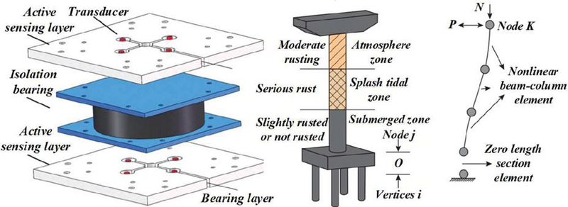
Figure 1 Stress state inside and outside of composite laminate surface.
The relationship between the pressure and the deformation on the foundation is analyzed by the elasticity theory. Under the elastic semi-space foundation model, the settlement of each point of the base is not only related to the pressure of the point, but also related to the forces of other points, so it is one step forward than the Venkel foundation model. However, because the foundation soil is not an ideal homogeneous, isotropic elastomer, the settlement of the foundation and the foundation calculated by the foundation model is often too large. Figure 2 is the axial force distribution diagram of the main supporting components. Considering the characteristics of natural stratification, and the compression characteristics and the limited compression depth of the foundation soil, the layered foundation model, or limited compression foundation model, is proposed. In the analysis, the model uses elastic theory to calculate the stress in the foundation. The layered foundation model can better reflect the changing characteristics of the soil layer under the foundation. It has accumulated a lot of experience in practice, and the combined analysis can get satisfactory results, which is generally between the Wenkel foundation and the elastic semi-space foundation. Layer to isotropic body refers to through the elastomer internal each point has its elastic properties in each direction is obviously inconsistent with the experimental results, so people established many foundations soil stress-strain relationship of non-linear elastic model, nonlinear elastic model has roughly three types: Cauchy elastic model, super elastic model and subelastic model.
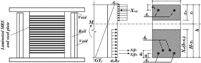
Figure 2 Axial force distribution diagram of the main supporting members.
Cauchy The elastic model is that the stress of elastic material only depends on the current strain; the hypetraelastic model is a kind of constitutive equation established by the material strain residual energy or residual energy function; the subelastic model means that the stress state of elastic material. Famous Duncan-zhang model belongs to subelastic model, test constant only nine, each parameter has certain physical and geometric meaning, and can be found by conventional triaxial test, and elastic tangent modulus matrix has symmetry, is beneficial to realize numerical calculation, elastic-plastic model can simulate soil stress-strain characteristics, better reflect the material hardening, softening, shear and the influence of the main stress and stress path, but the model parameters are difficult, and finite element calculation stiffness matrix asymmetry.
3.2 Finite Element Analysis Under the Line Elastic Foundation Model
The flexible foundation is like a soft film placed on the foundation. It cannot diffuse the stress, and the substrate reaction force p distribution is exactly consistent with the load q acting on the foundation. Due to the central load, the rigid base is originally a flat base, which is still kept flat after settlement, and the foundation is uniformly sinking. Thus, if the stiffness of the foundation is not the same, the impact on the foundation will be different, and then the impact on the superstructure will be different. Figure 3 shows the assessment diagram of the influence of foundation settlement on the superstructure. It shows the internal force redistribution caused by the change of foundation stiffness by the actual model test. Therefore, when considering the interaction between the superstructure, foundation and foundation, it is necessary to analyze the specific problems specifically and choose the appropriate foundation. Only through the excavation, drainage and other ordinary construction procedures can be built up of the foundation is called a shallow foundation.
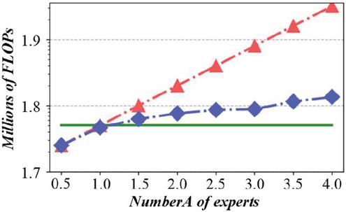
Figure 3 Assessment diagram of the influence of foundation settlement on the superstructure.
Because the shallow soil is bad or the building load is too large, the foundation bottom surface should be placed on a deep good soil layer, and the construction of more complex foundation is called deep foundation. According to the structure, shallow foundation can be divided into: independent foundation, bar foundation, cross foundation, raft foundation, box foundation and shell foundation. As an exploratory study, this paper only introduces the results of the overall analysis of strip and independent foundation buildings. Throughout the process of foundation analysis and design, only the static balance stage between superstructure, foundation and foundation; second, only the direct interaction stage between foundation and foundation; third, the interaction stage of superstructure, foundation and foundation. Table 1 shows the width and height value of the foundation under the column. The first stage mainly adopts the method of structural mechanics to divide the whole static balance system into three parts, and each part is calculated separately, without considering the influence of the other two. So, this method only meets the static balance conditions of total load and total reaction force, did not consider the displacement of the superstructure and foundation contact surface continuous condition, nor consider the contact surface between the foundation and foundation, the superstructure internal force and deformation, the foundation and the foundation connection point of the internal force and deformation are inconsistent with the actual situation. However, it is only natural to use such a simplified analysis method.
Table 1 Width and height values under the column
| Column Name | Corner Column | Vertical Edge Column | Horizontal Column | Stele |
| Base width/m | 1.6 | 2 | 2.1 | 3.3 |
| Base height/m | 0.3 | 0.4 | 0.4 | 0.6 |
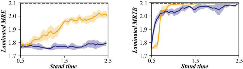
Figure 4 Weight comparison and evaluation diagram of the structure before and after optimization.
In the second stage, the displacement continuity and coordination between the foundation and the foundation are considered. This stage considers the influence of the design of the foundation, which is one step forward than the first stage. The substructure method is used to consider the interaction between the superstructure, foundation and foundation, which comes down to solving a system of balance equations considering the stiffness of the three factors. The following introduces the principle of substructure method to establish this system of equations. For this reason, the superstructure and foundation can be regarded as a whole. The basis of the boundary of the bottom of the boundary node, using the first modification of the base size, not only the basis of uneven settlement increase, and column bending moment value and beam bending moment value and beam shear value are generally increased, so the first modification of the base size of the whole structure stress more adverse, so that the structure more unsafe, this is not the result of what we want. Now another set of basic size values is used for numerical simulation analysis: the size of the corner column and the base under the side column is designed according to the conventional method, it can be seen that the shear force distribution law of the beam has not changed, but the shear force value decreases, and the relative difference of the shear force is also reduced. Furthermore, the data extraction and analysis of the maximum main stress value of each column and beam, Figure 4. For the weight comparison evaluation diagram of the structure before and after optimization, Using the second modified under-column foundation size, The smallest possible tensile damage area of the column and beam, Or, the smaller the uneven settlement, The smaller the damaged area of the superstructure appears, The safer the superstructure is, In addition, under various working conditions, The upper part of different columns is the most vulnerable or the earliest tensile damage, And each span beam is the central most easy to appear or the earliest pull damage; For the same column, The damaged area on the right side of the column should be greater than the left side; For the same beam, The lower part of the beam is more likely to pull damage than the upper part; To analyze the whole body, The maximum main stress value of the outer column should be greater than the inner column, That is to say, the side column is more prone to be damaged than the inner column; For the different layers of the beams, The lowest beam is the most easy or the earliest to pull damage.
4 Static Analysis and Optimization Design of Complex Building Structure Based on Finite Element Method
The phenomenon of soil deformation and stress and time is called the rheological phenomenon of soil, which is more obvious in clay, especially soft clay. The so-called “subconsolidation” in the soil is actually a one-dimensional rheology. In engineering, the rheology of soil mainly includes creep, relaxation and flow. In order to reflect the rheology of soil deformation or stress change, a variety of viscoelastic model, viscoplastic model and viscoelastic plastic model are put forward. Because it is difficult to accurately obtain the parameters of the rheological model of soil, the test is relatively complex, and other foundation models include internal time model, damage model and tip mutation model. But at present, these models are rarely used in the construction foundation engineering. Figure 5 for the earthquake structure dynamic response assessment diagram, however, due to the constitutive relationship of soil materials is influenced by many factors, the engineering properties of different kinds of soil may be significant difference, even in the same location of the consolidation state. From the practical point of view, the above various foundation models still coexist, different geotechnical problems, people use different foundation models for analysis. However, in terms of research and solution quantification accuracy, the closer the foundation model is to the real force and deformation state of the soil, the more accurate the analysis results are and the closer to the real situation. The foundation plays a connecting role in the whole building. Two foundation foundation in the base reaction force and the settlement of the foundation, first of all, the object or solution domain for a limited overlap only through the node connected subdomain unit, the original boundary conditions is also converted into node boundary conditions, this process is called discretization.
Figure 5 Assessment diagram of structural dynamic response under seismic action.
Second, within the cell, the simple approximation function is chosen to slice and approximate the unknown solution function, namely, the sharding approximation. The specific approach is to select some appropriate nodes on the unit as the interpolation point of the solution function, and rewrite the variables in the differential equation into a linear expression composed of the node value of various variables or its derivatives and the selected interpolation function, which is the idea and essence of the finite element method. And the analytic function on the overall region is a combination of simple approximation functions on these units. Whose node value of the variable or its derivative is the unknown quantity, and then the approximate solution of the original problem is obtained by means of matrix representation and algebraic equation system by computer. Absolute sedimentation value at the bottom of the line elastic model and Moore-Coulomb model. It is known that the absolute settlement under the linear elastic model is small and large under the Moore-Coulomb model. Therefore, from the comparison results of these two soil models, it can be seen that when the load and model structure are the same, using the Moore-Coulomb model can adjust the nonuniform settlement of the overall structure relatively well. Based on the comparison results of the superstructure column and beam bending and beam shear, we show that the decrease of uneven settlement is beneficial to the force of the superstructure. In addition, through the analysis of equivalent plastic strain value, although the axial force of the inner column is relatively large, and the absolute settlement value is larger than the side column and the corner column is larger than that of the vertical side column; the Angle column is the following order: first, the soil under the side column, and the bottom column is second. Figure 6 shows the evaluation diagram of the effect of temperature change on the internal force of the structure. In addition, it can be concluded that the value of plastic strain in areas with large displacement is not necessarily large, where otherwise, the value of plastic strain in areas with small displacement is not necessarily small. Distribution of bending moment values of each column or beam along the Y or X axis. Compared with the bending moment value of the linear elastic foundation model and the Moore-Coulomb model, the distribution law of the side column. However, from the quantitative analysis, the bending moment value obtained under the Duncan-tension model is the smallest, from which it can be inferred that the uneven settlement is the smallest under the Duncan-tension model.
Figure 6 Assessment diagram of the influence of temperature change on the internal force of the structure.
The shear force of each beam is reduced, but its distribution law is the same as that of the linear elasticity model and the Moore-Coulomb model. It can be seen that the settlement at the bottom of the foundation tends to be uniform, that is, the uneven settlement decreases, but the absolute settlement increases. According to the code for foundation design, the allowable value of the average settlement of the simple high-rise building foundation is 200 mm. Therefore, under the premise that the absolute settlement meets this requirement; in order to make the uneven settlement smaller, this paper considers from the perspective of changing the foundation size. Table 2 shows the axial force value at the bottom end of each column. Because the load of the whole structure and the stiffness of the structure are not formed at once, but with the construction process, and the step-by-step construction of the superstructure has an impact on the joint action of the superstructure, foundation and foundation. Therefore, we can set multiple step subsequent analysis steps in the Step module to simulate the superstructure load is gradually increasing. In essence, all the solid mechanics problems are nonlinear, and the linear elasticity problems are only a simplification of the practical problem.
Table 2 Axial force value at the bottom end of each column
| Horizontal | Medium | Medium | Medium | Horizontal | |
| Name | Column b1 | Column c1 | Column c2 | Column c3 | Column b2 |
| Axis force/kN | 1085.96 | 1806.91 | 1769.13 | 1810.08 | 1084.26 |
| Name | Corner column a2 | Vertical edge column d4 | Vertical edge column d5 | Vertical edge column d6 | Corner column a3 |
| Axis force/kN | 812.98 | 1040.12 | 1040.51 | 1043.43 | 815.43 |
For this paper, the value of the foundation is a limited area, with artificial boundary conditions to the actual situation, the boundary condition has some defects, because the foundation soil is an infinite area, which is the limitation of the finite element. Therefore, many scholars have proposed to use the boundary element or the infinite element to make up for the deficiency of the finite element. This is also the direction of further research in this paper.
Figure 7 Assessment diagram of node deformation under wind load.
5 Experimental Analysis
Meshing is the core technique of finite element analysis. Moreover, grid division is the most important and important link in the finite element modelling process with the largest workload. Figure 7 shows the evaluation diagram of node deformation under the action of wind load, cost and even success or failure. Therefore, the following principles must be followed in grid division: the principle of topological correctness; geometric conformal principle, the shape of the division unit, the same material properties, physical properties and interface conditions.
The numerical calculation shows that the ratio of the shortest edge and the longest edge in the grid is better at about 1:2, and it is better not to exceed 3, and the Angle of the edges should be no greater than 135 and not less than 30; the density control principle, the division of the grid should consider the accuracy of the calculation results, computer processing speed and the storage space required for the calculation results. Figure 8 shows the stress assessment diagram under the action of the dead weight of the structure. The more grids are divided, the higher the accuracy of the calculation results, but the larger the calculation amount, the larger the computer storage space is required. Considering the size of the personal computer storage space.
Figure 8 Stress assessment diagram under the dead weight of the structure.
Therefore, when dividing the grid, the grid cannot be divided evenly, but the dense grid division of the parts of attention, corresponding to the sparse grid division of the parts that are not much concerned. If the surface is not horizontal or soil layered irregular way can only use import stress data stress balance, the core of the method is to soil gravity, need to ignore the soil displacement, simply extract the average stress of each unit, then read the stress back to the ABAQUS as the initial stress, to achieve the effect of balancing soil displacement. Figure 9 evaluates the structural displacement under different load combinations, without the stress balance, the displacement value of each node under gravity, after subsequent calculation, the displacement value of the displacement result minus each node, but this method is only suitable for small deformation analysis, not suitable for geometric nonlinear, the advantage is good convergence, high accuracy, because record is node displacement, disadvantage is trouble, because to record in advance, and process data.
Figure 9 Assessment diagram of structural displacement under different load combinations.
Figure 10 Evaluation diagram of material characteristics of complex building structures.
From the perspective of relative settlement analysis, the relative settlement difference under elastic foundation model is the smallest, compared with the other two foundation model, the settlement is relatively uniform, the above calculation results not only related to the soil constitutive model, also related to the parameters in the model, the midline elastic model take the foundation deformation modulus is relatively large, shows that the soil stiffness is larger, so the absolute settlement and settlement difference is relatively small. The deformation modulus of the soil in the Moore-Coulomb model is actually corresponding to the shear modulus of the soil stress-strain curve, which may underestimate the stiffness of the soil, and the model is the ideal elastic plastic model after yield. Figure 10 shows the evaluation diagram of the material properties of complex building structure, which will also lead to the calculated settlement may be larger. However, the calculation results of the nonlinear Duncan-tension model based on the test curve fitting should be more reasonable and can more closely reflect the true stiffness of the ground soil. Since the building is usually constructed from bottom to top, that is, the load of the superstructure is applied on the foundation soil step by step, the absolute settlement equivalent cloud of the calculation model is analyzed by the Duncan-zhang model. It clearly shows the settlement change of the superstructure. The maximum settlement value appears in the northwest corner, and the distribution law of the settlement value is as follows: the value decreases along the southeast direction, that is, the superstructure slopes to the northwest direction.
6 Conclusion
The comparative analysis of the axial force value at the bottom end of the column shows that the results obtained using the Duncan-tension model are compared with the other two foundation models, and the corner column and the side column are unloaded while the middle column is loaded. Analysis of the calculation results of the bending moment of the frame structure column and the beam shows that the maximum value of the column or the beam changes at the junction between the beam and the column. According to the shear force results of the upper longitudinal beam of the frame structure, the shear force changes at the junction of the beam and the column and at the midpoint of each span beam, and the second layer beam is the largest than the shear force. The increase of the independent foundation size under the frame structure column can reduce the absolute settlement, but the relative settlement is diminished or increased in the role; the foundation size designed by conventional methods and the foundation size designed by the finite element method can significantly reduce the uneven settlement.
Three foundation models show that the absolute settlement is the largest while the linear elastic model is the smallest; the unloading amplitude is about 6%, the unloading amplitude is about 14%, and the axial force value at the bottom of the side column is about 8%. And uneven settlement when using the line elastic foundation model, the above calculation results not only related to the selected soil of constitutive model but also related to the parameters in the model, the midline elastic model of the foundation deformation modulus is relatively large, shows that the soil stiffness is more significant. Hence, the absolute settlement and settlement difference is relatively small. The maximum MISES stress is significantly reduced; the maximum MISES stress is 9299.49 kPa, the maximum MISES stress is 7332.74 kPa, and the reduction amplitude is about 20%. The deformation modulus of the soil in the Moore-Coulomb model is actually on the soil stress-strain curve is 1/2 damage strain, which may underestimate the soil stiffness, and the soil is an ideal elastic and plastic model, the soil yield after zero, which will lead to the calculated settlement may be significant. However, the nonlinear Duncan-tension model calculation results based on the test curve fitting should be more reasonable. They can more closely reflect the actual stiffness of the ground soil.
References
[1] J. Abramczyk, “Transformed Corrugated Shell Units Used as a Material Determining Unconventional Forms of Complex Building Structures,” Materials, vol. 14, no. 9, pp. 29, 2021.
[2] A. V. Bergami, “Design of Additional Dissipative Structures for Seismic Retrofitting of Existing Buildings,” Applied Sciences-Basel, vol. 14, no. 6, pp. 15, 2024.
[3] P. M. Bhatt, R. K. Malhan, P. Rajendran, and S. K. Gupta, “Building free-form thin shell parts using supportless extrusion-based additive manufacturing,” Additive Manufacturing, vol. 32, pp. 15, 2020.
[4] A. Choroszucho, B. Butrylo, A. Steckiewicz, and J. M. Stankiewicz, “Determination of the Effective Electromagnetic Parameters of Complex Building Materials for Numerical Analysis of Wireless Transmission Networks,” Electronics, vol. 9, no. 10, pp. 18, 2020.
[5] D. H. Dong et al., “Building Extraction From High Spatial Resolution Remote Sensing Images of Complex Scenes by Combining Region-Line Feature Fusion and OCNN,” Ieee Journal of Selected Topics in Applied Earth Observations and Remote Sensing, vol. 16, pp. 4423–4438, 2023.
[6] S. Eberhardt and M. Pospisil, “E-P Heritage Value Assessment Method Proposed Methodology for Assessing Heritage Value of Load-Bearing Structures,” International Journal of Architectural Heritage, vol. 16, no. 11, pp. 1621–1641, 2022.
[7] M. El Hoseny, D. Forcellini, and J. X. Ma, “The role of the foundation gap on the pounding between low-rise buildings,” Structures, vol. 63, pp. 11, 2024.
[8] A. Fazel, R. Fayaz, A. Mostaghni, and M. R. Matini, “Optical tool for additive construction of complex brick structures,” Automation in Construction, vol. 140, pp. 11, 2022.
[9] A. C. Günaydin and A. R. Yildiz, “A comparison of recent optimization algorithms for build orientation problems in additive manufacturing,” Materials Testing, vol., pp. 18, 2024.
[10] A. C. Günaydin, A. R. Yildiz, and N. Kaya, “Multi-objective optimization of build orientation considering support structure volume and build time in laser powder bed fusion,” Materials Testing, vol. 64, no. 3, pp. 323–338, 2022.
[11] H. S. Guo, J. H. Xu, S. Y. Zhang, Y. M. Zhang, and J. R. Tan, “Multi-orientation optimization of complex parts based on model segmentation in additive manufacturing,” Journal of Mechanical Science and Technology, vol. 37, no. 1, pp. 317–331, 2023.
[12] E. Heo et al., “Precise and selective macroscopic assembly of a dual lock-and-key structured hydrogel,” Materials Horizons, vol. 11, no. 2, pp. 428–441, 2024.
[13] X. Y. Hu, Z. P. Zhao, E. Barredo, K. S. Dai, Y. N. C. Tang, and N. Hong, “Nonlinear Viscous Damping-Based Negative Stiffness Isolation System with for Over-Track Complex Structures,” Journal of Earthquake Engineering, vol. 28, no. 11, pp. 3146–3174, 2024.
[14] M. F. Huang, G. Tang, and Y. Q. Ni, “Reliability assessment of a building complex with four long-span roof structures based on wind tunnel experiments,” Journal of Civil Structural Health Monitoring, vol. 11, no. 5, pp. 1461–1475, 2021.
[15] D. Y. Jiang and F. D. Ning, “Anisotropic deformation of 316L stainless steel overhang structures built by material extrusion based additive manufacturing,” Additive Manufacturing, vol. 50, pp. 13, 2022.
[16] X. L. Jin et al., “Integrated optimal scheduling and predictive control for energy management of an urban complex considering building thermal dynamics,” International Journal of Electrical Power & Energy Systems, vol. 123, pp. 13, 2020.
[17] V. K. Kachanov, V. G. Kartashev, I. V. Sokolov, R. V. Kontsov, and E. I. Trunov, “Ultrasonic Tomograph of Concrete Building Structures with Lateral Signal Radiation,” Russian Journal of Nondestructive Testing, vol. 56, no. 2, pp. 110–118, 2020.
[18] M. Kheirollahi and M. Mirzaei, “Seismic evaluation and retrofitting of the structures of the Sadaghiani masonry historical complex,” Case Studies in Construction Materials, vol. 19, pp. 20, 2023.
[19] M. L. Leonardi, J. Granja, D. V. Oliveira, and M. Azenha, “Scalable BIM based open workflow for structural analysis of masonry building aggregates,” Computers & Structures, vol. 297, pp. 17, 2024.
[20] B. Li and C. X. Cheng, “Quantifying the impact of buildings on land surface temperature: Intrinsic structure and extrinsic morphology,” Building and Environment, vol. 259, pp. 11, 2024.
[21] H. Li, J. P. Liu, J. Li, W. Wei, and W. C. Shan, “Intelligent optimization method for complex steel structures based on internal force state,” Journal of Constructional Steel Research, vol. 218, pp. 12, 2024.
[22] X. L. Li et al., “Facile synthesis of three-dimensional porous graphene nanostructures from coordination complexes for supercapacitor electrode,” Advanced Powder Technology, vol. 31, no. 10, pp. 4157–4165, 2020.
[23] Z. H. Li, G. Q. Huang, X. Z. Chen, and X. H. Zhou, “Seismic Response and Parametric Analysis of Inter-Story Isolated Tall Buildings Based on Enhanced Simplified Dynamic Model,” International Journal of Structural Stability and Dynamics, vol. 22, no. 03N04, pp. 36, 2022.
[24] J. Lu et al., “Graph convolutional networks-based method for estimating design loads of complex buildings in the preliminary design stage,” Applied Energy, vol. 322, pp. 17, 2022.
[25] K. Mayar, D. G. Carmichael, and X. S. Shen, “Resilience and Systems-A Building Structure Case Example,” Buildings, vol. 13, no. 6, pp. 17, 2023.
[26] A. Mekhtiyev et al., “Developing an Intelligent Fiber-Optic System for Monitoring Reinforced Concrete Foundation Structure Damage,” Applied Sciences-Basel, vol. 13, no. 21, pp. 23, 2023.
[27] G. Minafò, G. Rusticano, L. La Mendola, and S. Pennisi, “Procedure for Safety Assessment and BIM Modelling of an Historical Complex Structure through a Macroelement Approach: The Building “Molino-Pastificio Soresi” of Partinico (Italy),” Buildings, vol. 12, no. 9, pp. 20, 2022.
[28] D. Murià-Vila, O. A. Delgado, G. G. A. Silva, D. A. Lara, and K. Pérez-Liévana, “Monitoring of a rehabilitated building in soft soil in Mexico and structural response to September 2017 earthquakes: Part 2: Numerical simulation,” Earthquake Spectra, vol. 36, no. 2_SUPPL, pp. 238–261, 2020.
[29] M. A. Orabi, A. A. Khan, L. M. Jiang, T. Yarlagadda, J. Torero, and A. Usmani, “Integrated nonlinear structural simulation of composite buildings in fire,” Engineering Structures, vol. 252, pp. 17, 2022.
[30] B. Ortiz-Viso, A. Morales-Garzón, M. J. Martin-Bautista, and M. A. Vila, “Evolutionary Approach for Building, Exploring and Recommending Complex Items With Application in Nutritional Interventions,” Ieee Access, vol. 11, pp. 65891–65905, 2023.
Biographies

Huaiping Peng graduated with a bachelor’s degree in Civil Engineering from Nanyang University of Technology in July 2009. He is currently working as an teacher at the School of Civil Engineering and Architecture, Zhengzhou Urban Construction Vocational College, with the title of Senior Engineer. His research areas and directions include civil engineering, architectural economics, and project management.

Zhongyuan Li received the master’s degree in engineering from Shenyang Jianzhu University in 2009. He is currently working as an teacher at the School of Civil Engineering and Architecture, Zhengzhou Urban Construction Vocational College. His research areas and directions include Structural Engineering and Engineering Project Management.
European Journal of Computational Mechanics, Vol. 33_6, 561–582.
doi: 10.13052/ejcm2642-2085.3362
© 2025 River Publishers