Investigation of Forced Vibrations and Phase Change of an Annular Sector Plate Made of Shape Memory Alloy in the Superelastic State
Amir Hossein Nasrollah Barati* and Reza Shahveh
Department of Mechanical Engineering, Al.C., Islamic Azad University, Aligudarz, Iran
E-mail: amir.barati@iau.ac.ir
*Corresponding Author
Received 08 January 2025; Accepted 26 May 2026
Abstract
The present work examines free and forced vibrations of shape-memory alloy (SMA) annular sector plates. The first-order shear deformation theory is utilized to analyze the plate. The Boyd-Lagoudas constitutive model is used to simulate pseudoelastic behavior. Hamilton’s principle is employed to obtain motion equations. The sector plate time response and sector plate frequency response are derived via the return mapping algorithm, Newmark method, and differential quadrature method (DQM). In addition, the numerical results of the force vibrations and the effects of the different geometrical parameters on the dynamic response of the plate are investigated. Finally, the findings of this study are verified using the finite element method (ABAQUS software) and the findings of other studies.
Keywords: Dynamic response, annular sector plate, shape memory alloy, pseudoelastic, differential quadrature method.
1 Introduction
In recent decades, shape memory alloys, due to having two characteristics of shape memory and superelastic, have become widely the focus of research [1]. The superelastic characteristics of these alloys caused researchers to examine their dynamic behavior. These materials are widely used due to their distinctive characteristics, including biocompatibility, corrosion resistance, improved yield stress, and durability. Shape memory alloys are utilized in several applications, including biomedical, automotive, oil exploration, and aerospace applications. In addition, structures made of shape memory alloys (SMAs) are utilized in various fields, including blood pressure Holters, prosthetic heart valves, and prosthetic meniscus. However, they may be exposed to specific working circumstances and exhibit nonlinear behavior. Therefore, for various sectors, nonlinear analysis of plates can be pretty important.
Park et al. [2] studied the vibration behavior of a thermally buckled composite plate embedded with SMA fibers. The results showed a rise in the critical temperature and a reduction in the large thermal deflection using the SMA fibers. Du et al. [3] evaluated the deflection of an epoxy beam with SMA wires subjected to lateral load and transient ambient temperature. They used Brinson’s one-dimensional constitutive model to analyze the SMA wires. The results showed that more SMA wires were needed for a clamped beam than a simply supported one in order to effectively control the beam deflection. Hashemi and Khadem [4] developed a mathematical model based on the Auricchio model, considering asymmetry in tension and compression, along with temperature effects on hysteresis in superelastic conditions. According to the results, the superelasticity led to diminished response amplitude tending to an elastic limit. Saidi et al. [5] evaluated the free vibrations of functionally graded (FG) annular sector plates. A total of nine boundary conditions were employed to precisely perform the natural frequency calculation of the plates at different thickness-to-length ratios, aspect ratios, power-law indexes, and sector angles. Hejripour and Saidi [6] studied the nonlinear free vibration of isotropic annular sector plates using the differential quadrature method (DQM). They applied the geometric nonlinearity to the strains and obtained the nonlinear governing equations of motion based on the first-order shear deformation plate theory. They also used the harmonic balance method to obtain the eigenvalue system. Asadi et al. [7] performed an analytical investigation on large-amplitude vibrations and thermal post-buckling of shape memory alloy fiber-reinforced hybrid composite beams with both symmetric and asymmetric lay-up. They utilized the Euler-Bernoulli beam theory and the nonlinear Von Karman strain field to forecast the behavior of the smart laminated beam. The findings indicated varied values for the prestrain and volume fraction of SMA fibers. The fundamental frequency of the hybrid beam rose in the pre-buckling phase and diminished in the post-buckled region.
Asemi et al. [8] analyzed two-dimensional FG annular sector plates in three-dimensional static and dynamic settings. Material properties were assumed to change consistently in both radial and axial directions. The three-dimensional equations were solved in the time domain and space domain by using the Newmark direct integration and graded finite element techniques. Volkov et al. [9] evaluated a vibroisolation system consisting of a payload connected to a vibrating housing by plane SMA slotted elements. They determined the mechanical behavior of the SMA based on a microstructural theory. The results indicated that the protective properties of the system depended on the SMA state. Moreover, the maximum reduction of the acceleration amplitude for harmonic excitation was achieved when the SMA was in either the martensitic (pseudo-plastic) or the two-phase state. Forouzesh and Jafari [10] examined the forced vibration of a cylindrical shell composed of SMA. The researchers examined the impact of internal pressure on phase transition and its durability. The principal findings of their research indicated that the phase transition of the alloy resulted in a diminished tensile modulus and alloy strength, leading to an increased amplitude of forced vibration. Auricchio et al. [11] examined the fatigue and ultimate strength of SMAs. They discovered that the propagation of fatigue cracks in SMA materials could be predicted using a two-scale Dang Van criterion, which was also suitable for multi-axis loading.
Ashrafi et al. [12] investigated the size effects on the nonlinear free vibration of a sandwich composite microbeam with an extensible SMA layer in the mid-plane. The pseudoelastic behavior simulation of the SMA layer was carried out using a one-dimensional constitutive model. Hamilton’s principle, the modified coupled stress theory, and Euler-Bernoulli beam theory were exploited to derive the motion equations. The obtained results showed that micro-beam damping performance was found to be intensely dependent on the initial velocity. Adeodato et al. [13] studied the vibrations resulting from the combination of shape memory alloys and piezoelectric materials for energy harvesting. Their results showed that using the combination of shape memory alloys and piezoelectric materials improves the system’s performance for energy harvesting. Nasrollah Barati et al. [14] investigated the free and forced vibrations of a circular plate made of a shape memory alloy in contact with a fluid. They derived the governing equations based on the first-order shear deformation theory and Hamilton’s principle. They presented a fast and accurate numerical method for the nonlinear behavior of the shape memory alloy. Tabrizikahou et al. [15] provide an overview of the most commonly used constitutive modeling and SMA-based applications, along with their limitations in seismic isolation devices and structural vibration control. Barati et al. [16] studied the dynamic response of a plate made of shape memory alloy. A numerical solution was presented using the DQM, the Newmark method, and the return mapping algorithm. Additionally, the effect of the applied pressure on displacement, martensite volume fraction, and elastic modulus was investigated.
The review indicates that, despite extensive prior research on the vibration of plate structures, no studies are available on the vibration analysis of annular sector plates made of shape memory alloy. This study examines the pseudoelastic vibrational behavior of an annular sector plate composed of shape memory alloy subjected to harmonic pressure. This paper presents a numerical method to obtain the natural frequency and dynamic response of a sector plate subjected to a harmonic load using the DQ method. The governing equation is derived using first-order shear deformation theory and Hamilton’s principle.
The behavior of SMA is modeled using the Boyd-Lagoudas constitutive model. Additionally, the DQ and Newmark methods are coupled with the return mapping algorithm to analyze the time and frequency response of the sector plate. The proposed numerical method is verified by comparing the results obtained here with the studies in the literature and ABAQUS software. Finally, the effects of parameters such as aspect ratio and sector angle are investigated.
2 Shape Memory Alloy
2.1 Definition
Smart materials have properties making them attractive alternatives for industrial applications in many branches of engineering. Among the various types of smart materials, SMAs have unique properties, including high-temperature austenite phase and low-temperature martensite [1]. This study investigates the pseudoelastic behavior of SMAs. Figure 1 demonstrates the stress-strain diagram of the quasi-elastic effect, in which the loading and unloading conditions have created a hysteresis loop in the material, leading to a reduction in energy at the internal surface. The following describes the loading-unloading path in a complete cycle.
Step (1–2) is the linear loading path of pure austenite with Young’s modulus of (Young’s modulus in the pure austenitic phase). Step (2–3) is a forward phase transformation path combining the austenite and martensitic phases. Step (3–4) is a linear elastic loading path, as a pure martensitic phase with Young’s modulus of (Young’s modulus in the pure martensitic phase). Step (4–5) is an elastic unloading path as a pure martensitic phase. Step (5–6) is a reverse-phase transformation path combining the martensitic and austenite phases. Step (6–1) is an elastic unloading path with Young’s modulus of (Young’s modulus in the pure austenitic).
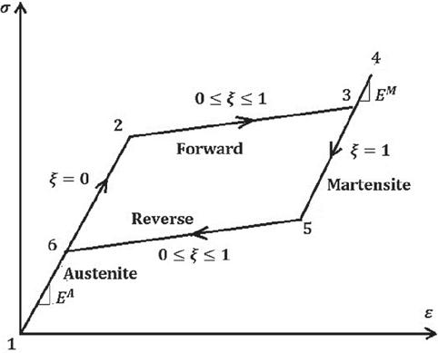
Figure 1 Schematic of a pseudoelastic stress-strain diagram [1].
2.2 Governing Equations
Based on Gibbs free energy, Boyd and Lagoudas [1] proposed a constitutive model for SMAs as a function of stress (), temperature (), martensitic volume fraction (), and strain transformation defined as follows:
| (1) |
where , and denote the density, effective compliance tensor, effective thermal expansion tensor, reference temperature, effective specific heat at the reference state, effective specific entropy at the reference state, and effective internal specific energy at the reference state, respectively. The material parameters can also be calculated based on the martensitic volume fraction:
| (2) |
where the superscripts and denote the pure austenitic and martensitic phases, respectively. Moreover, the operator shows the variations in the quantitative changes in two complete phases. Other material properties, such as Young’s modulus, can be calculated through the Equation (2.2). Moreover, is the martensitic volume fraction phase with a value between 0 and 1, where for fully austenite material, for fully martensitic material, and for the forward and reverse phase transformation. In order to consider the interactions between two martensitic and austenitic phases, the hardening function, is defined as:
| (3) |
The first condition related to the forward phase transformation (austenitic to martensitic) and the second () is related to the reverse phase transformation (martensitic to austenitic). The symbol (:) indicates the first derivative with respect to time. Furthermore, , and are the model parameters obtained from:
| (4) |
By combining the first and second laws of thermodynamics, the Clausius-Planck inequality is obtained as:
| (5) |
where and are the entropy and strain tensor, respectively. By substituting the time derivative of Gibbs free energy obtained from the chain rule into Equation (5), the Clausius-Planck inequality is determined as:
By fixing all variables except for T, since the temperature changes can be positive or negative, its coefficients must be zero to satisfy the equation. Moreover, by fixing all variables except for , for unequal satisfaction, its coefficients must be zero, for which the entropy and strain equations can be proposed by:
| (7) |
By substituting Equation (1) into Equation (7), the entropy and strain tensors are determined as [1]:
| (8) |
Moreover, by substituting Equation (7) into Equation (6) and using Equation (1), Clausius-Planck inequality is given as:
| (9) |
According to the flow law, time changes of strain transformation and martensitic volume fraction can be written as:
| (10) |
in which is the transformation tensor and is expressed as:
| (11) |
where , and are the deviatoric stress tensor, effective stress, existing transformation strain at the reversal point of the transmission path, and effective transformation strain at the reversal point, respectively, and denotes the maximum strain transformation. Furthermore, , and are given by:
| (12) |
in which is the identity tensor and indicates the trace of the stress tensor. By substituting the flow law into Equation (9), the Clausius-Planck inequality can be expressed as:
| (13) |
where is the transformation dissipation potential and is the total thermodynamic force defined as Equation (14):
| (14) |
The Clausius-Planck inequality must be satisfied for both forward and reverse phase transformation paths. The martensitic phase transformation occurs when the thermodynamic force reaches a critical value. Consequently, is positive for the forward phase transformation and negative for the reverse phase transformation . In addition, is defined as one of the model parameters, which describes the amount of internal damping due to the microstructure changes in phase transformation:
| (15) |
The critical value of the thermodynamic force is for the forward path and for the reverse path. The transformation function is defined as Equation (16):
| (16) |
In the thermoelastic phase transformation (forward-reverse), the condition is satisfied. Besides, in loading and unloading of pure austenite and martensite, when the martensitic volume fraction is not changed in these paths (), the condition is met. The explained conditions are called Kuhn-Tucker conditions. Moreover, in phase transformation, the stress and temperature should remain on these surfaces, This condition indicating a consistency condition that is expressed as .
2.3 Convex Cutting Plane Return Mapping Algorithm
The function of the convex cutting return mapping algorithm is based on the explicit integration of differential equations and computes state variables, such as martensitic volume fraction and transformation strain, according to a specific strain field [1]. In this study, the return mapping algorithm is applied for numerical integration of governing thermo-mechanical equations of the SMA materials. the differential form of governing equations of shape memory alloy (Equation (2.2)) is written as Equation (17):
| (17) |
By applying the flow law and Equation (2.2), Equation (17) can be rewritten as Equation (18):
| (18) |
The differential form of the stress tensor is presented as:
| (19) |
By comparing Equation (19) with Equations (14) and (16), the following expression yields:
| (20) |
in which is the partial derivative of the transformation function with respect to . According to the consistency condition, Equation (21) is obtained:
| (21) |
where and are the partial derivatives of the transformation function with respect to T and , respectively. By substituting Equation (20) into Equation (21), the differential of martensitic volume fraction is obtained as Equation (22):
| (22) |
The increment stress tensor for the th iteration is given by:
| (23) |
By linearizing the transformation function for the th iteration using the Newton-Raphson iteration method and applying the condition for the transformation function to be zero at the end of the iteration process, Equation (24) can be written as:
| (24) |
Therefore, by substituting Equation (23) into Equation (24), the increased martensitic volume fraction is calculated using Equation (25):
| (25) |
where is the stiffness tensor. The increased strain tensor transformation for the th iteration is calculated as:
| (26) |
Equation (27) is used to update the strain transformation, martensitic volume fraction, and stress tensor:
| (27) |
Through the return mapping algorithm pattern, the state variables are determined for each temperature and specified strain tensor. For this purpose, in the study time, the converged internal state variables related to the previous time are utilized as the initial assumption for the present time. If the condition is established, the values of internal state variables at the present time are equal to the initial assumption. Otherwise, if , the iteration should be implemented as long as the condition is established. The steps of the return mapping algorithm of cutting convex planes are represented in Figure 2.
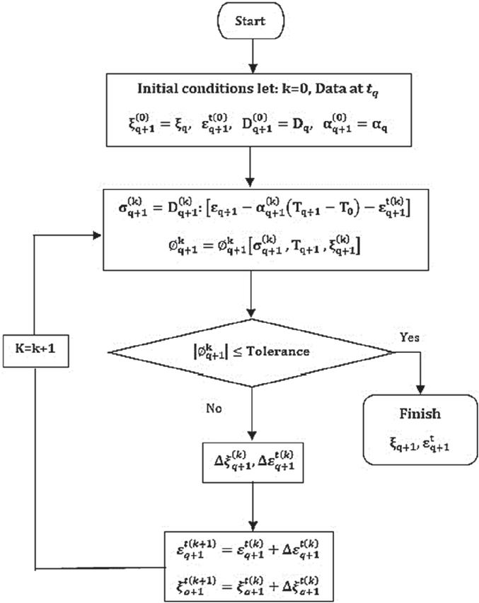
Figure 2 SMA convex cutting plane return mapping flowchart.
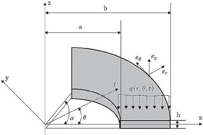
Figure 3 Harmonically-loaded SMA annular sector plate.
3 Formulation
Figure 3 illustrates an SMA annular sector plate subjected to a harmonic load. The symbols , and denote the internal radius, external radius, thickness of the annular sector plate, and sector angle, respectively.
Under first-order shear deformation plate theory within the polar coordinate system, the displacement field for the sector plate can be articulated as [17]:
| (28) |
where denotes the thickness coordinate and , and represent the displacements along the , and axes, respectively. Furthermore, and represent the displacements of the mid-plane in the and axes, respectively. and denote the rotational displacements around the and axes, respectively. The strain components of the SMA sector plate can be determined as follows, by assuming small strain-displacement relationships [17]:
| (29) |
3.1 Hamilton’s Principle
The governing equations are obtained from Hamilton’s principle [15]:
| (30) |
where T, U, and denote the kinetic energy, strain energy, and the work of external loads, respectively. The kinetic and strain energies are expressed as Equation (31) [6]:
| (31) |
The stress resultants (membrane forces , bending moments , and transverse shear forces ) are obtained by thickness-integration of stresses in the standard manner of FSDT. The external excitation is taken as a harmonic transverse load:
| (32) |
where and are the load amplitude and excitation frequency, respectively. Substituting the kinematic relations into the energy expressions and enforcing Hamilton’s principle yields the coupled equations of motion.
3.2 Final Equations of Motion with SMA Constitutive Behavior
By substituting the SMA constitutive relations into the equilibrium equations (Equation (42)), the final governing equations of motion for the annular sector plate are obtained. To address the reviewer’s comment and for the sake of brevity, the expanded expressions are written in the following compact operator form:
| (33) |
where and denote the differential operators associated with the elastic stiffness terms and the SMA transformation strain contributions, respectively; , and are the standard inertial coefficients of FSDT. The SMA effect enters the formulation through the parameter , defined as [1]:
where and are the Young’s moduli of austenite and martensite, respectively, and is the martensitic volume fraction. The transformation strain components are evaluated using the Boyd-Lagoudas model described in Section 2 and contribute to the governing equations through . Since depends on , which may vary spatially within the plate, this dependence is inherently embedded in the operators . Under the superelastic condition ( and ), the phase transformation is purely stress-induced and thermal strain terms vanish.
4 Numerical Methods
This work employs two numerical approaches to examine the vibrations of the annular sector plate. The DQM is an efficient and precise technique for numerically solving governing differential equations. The solution domain is discretized into N discrete grid points in accordance with DQM. As a result, the derivative at each point is a linear collection of weight coefficients and function values that are displayed along a coordinate axis in both that point and other domain points. In the grid , the partial derivative of order n for function with respect to r and the partial derivative of order s for the function with respect to could be found as:
| (34) |
where signifies [5], Also, represents the weight coefficient in the rdirection, while is the weight coefficient in the -direction. The results of this method are contingent upon the choice of weight coefficients. In this work, polynomial test functions are employed as weight coefficients for the transverse displacement and transformation strain functions, as specified below [18]:
| (35) |
The selected points are assumed at equal spaces in the two direction [19]:
| (36a) | ||
| (36b) |
By applying DQM in Equation (3.2), the following expression yields:
| (39) |
where the displacement vectors of the boundary points and the governing differential equation are represented by the vectors and , respectively, and is the vector of all displacements. The second derivative with respect to time is denoted by the . Furthermore, M and k are the mass and stiffness matrices, respectively, that vary with throughout the material’s phase transition. Additionally, the external pressure vector is denoted by , and the transformation strain vector is denoted by The time integration step of the equation was executed via the Newmark method. The Newmark approach presumes the velocity vector and acceleration vector to be [20]:
| (40) |
where the displacement, velocity, and acceleration vectors are denoted by , and , respectively. Also, , in which denotes the present time, is the time step, and is the previous time. The symbols and be used for parameters for regulating the precision and stability of the procedure, with values of 0.5 and 0.25, respectively [20]:
| (41) |
By substituting Equation (40) into Equation (39), Equation (42) is obtained. Based on Equation (40), present-time displacement vector calculation is carried out using the previous-time vectors of displacements, velocities, and accelerations:
| (42) |
This study assumes that the annular sector plate has simply supported boundary conditions in radial edges and arbitrary boundary conditions at the circular edges. The boundary conditions can be yield as:
(1) Clamped
On the circular edges
| (43a) |
(2) Simply supported
On the circular edges
| (44a) |
On the straight edges
| (45a) |
The displacement components and rotation functions for examining the plate’s natural frequencies in the pure austenitic phase (linear system) are defined as follows in order to satisfy the conditions in Equation (45):
| (46) |
where is the natural frequency of the th mode, is the number of circumferential waves, and . By installing Equation (46) into Equation (3.2), employing the DQM, and applying boundary conditions, Equation (39) is rewritten as Equation (47), where both vectors and are removed. The natural frequencies are derived by satisfying . Due to the martensitic volume fraction is zero, all components of transformation strain are eliminated:
| (47) |
5 Numerical Results and Discussion
In this research, an iterative process has been used to obtain displacement and acceleration vectors. In order to calculate matrices , and vector in the present time, the values of the martensitic volume fraction and strain tensor transformation are first taken into consideration as an initial assumption. The displacement vector is subsequently determined using the Newmark method. Subsequently, the strain tensor associated with the displacement vector is derived in the current time using straindisplacement equations. The strain tensor is determined using the return mapping algorithm to get and . Then, based on the new values of and , the matrices and the vector are updated.
In the next mode, the Newmark method obtains the displacement vector based on the modified values. The iteration procedure then ends, and the displacement vector is regarded as the final answer if the difference between the displacements in the first and second steps is less than a certain value. If not, the procedure is repeated until the displacement difference is less than a specified tolerance.
This section provides numerical vibration results for a Ni-Ti SMA annular sector plate. Table 1 contains a list of this alloy’s characteristics. The plate is initially in the pure austenitic phase.
Table 1 Material parameters of Ni-Ti SMA [1]
| Material Parameter (Unit) | Value |
| H | 0.05 |
| 295 | |
| 315 | |
| 291 | |
| 271 | |
| 0.33 | |
| 6450 | |
| 70 | |
| 30 | |
| 22E-6 | |
| 0.35 | |
| 0 | |
| ∗Superscripts A and M refer to austenitic and martensitic phases, respectively. | |
In the present study, the SMA, DQM, and Newmark codes are proposed by MATLAB software to study the forced vibration of the annular sector plate and the nonlinear behavior of its time and frequency responses. The SMA code using the return mapping numerical algorithm is also written according to the Boyd-Lagoudas constitutive model. The appropriate number of points in DQM is determined from the response convergence test, where is utilized in the forced vibration analysis of the plate. Furthermore, in order to validate the results, the problem is simulated in the ABAQUS finite element software. A good agreement has been observed between the results.
The comparison of the dimensionless natural frequencies of the annular sector plate made of the shape memory alloy in the pure austenite (isotropic) state, for various boundary conditions and angles is shown with the results reported by Saidi et al. [5] in Table 2. Excellent agreement has been observed for all cases.
Table 2 Comparison of dimensionless frequencies of annular sectors plate of shape memory alloy in the austenitic phase (isotropic) with the ratios (, ) [14]
| BC | 45 | 120 | 240 | 360 | |
| SSCC | [5] | 194.9900 | 167.0994 | 164.2395 | 163.7256 |
| Present Study | 194.5310 | 166.541 | 163.721 | 163.1011 | |
| SSCS | [5] | 150.9370 | 117.4119 | 113.7661 | 113.1064 |
| Present Study | 150.7239 | 117.1021 | 113.309 | 112.8556 | |
| SSSC | [5] | 167.3939 | 126.8383 | 122.1422 | 121.2835 |
| Present Study | 167.0120 | 126.3191 | 121.8567 | 120.8985 | |
| SSSS | [5] | 130.3982 | 84.7699 | 79.1489 | 78.1096 |
| Present Study | 130.0267 | 84.3895 | 78.7751 | 77.7123 | |
Furthermore, the displacement values of a mid-radial annular plate grid point with different angles and under the pressure corresponding to the phase transformation can be compared with those of the ABAQUS finite element software in Table 3, indicating good convergence.
Table 3 Comparison of transverse displacement mid-radial annular plate grid point sector plate made of SMA under harmonic load ratio for (, )
| BC | ||||
| SSCC | 60 | MPa | Present Study | 0.0124 |
| FEM | 0.0136 | |||
| 120 | MPa | Present Study | 0.0577 | |
| FEM | 0.0634 | |||
| 210 | MPa | Present Study | 0.0724 | |
| FEM | 0.0796 | |||
| 240 | MPa | Present Study | 0.0740 | |
| FEM | 0.0814 | |||
This section discusses the vibrational behavior of a sector plate with in phase transformation conditions. An annular sector plate is analyzed for numerical results, characterized by the geometric ratios and . Figure 4 illustrates the stress-strain and transverse displacement of the mid-radial annular plate grid point () against time under external pressure in one cycle. For this purpose, the time period and pressure coefficient are considered 0.005 s and 1 MPa, respectively.
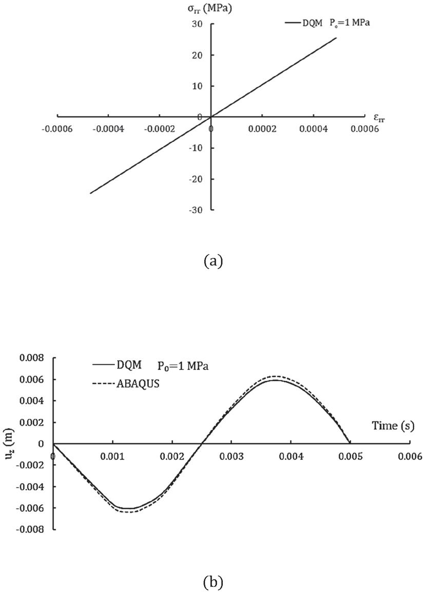
Figure 4 Responses of the mid-radial annular plate grid point for the time period of 0.005 s and MPa: (a) stress-strain response along r-axis and (b) comparison of transverse displacement-time with ABAQUS.
As shown in Figure 4, the selected intensity of external pressure is initially at a level that does not cause a phase change in the material, which remains in the pure austenitic phase. Under these conditions, the martensitic volume fraction and transformation tensor are zero. Results have been confirmed utilizing ABAQUS. The results exhibit good agreement. Figure 5(a) depicts the transverse displacement of the mid-radial annular plate grid point versus time for the time period of 0.005 s and different values of . According to Figure 5(a), the displacement of the plate has several behaviors and shows different slopes in the amplitude due to the phase transformation. These behaviors are attributed to the applied pressure and phase transformation of the material. In Figure 5(b), the transverse displacement of the mid-radial annular plate grid point under a pressure of 2.1 MPa is compared with the results obtained from ABAQUS.
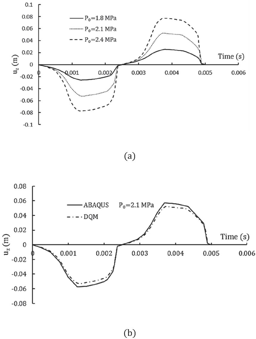
Figure 5 (a) Transverse displacement of the mid-radial annular plate grid point for various pressure amplitudes and time period of 0.005 s. (b) Comparison of transverse displacement-time diagrams of the mid-radial annular plate grid point for pressure amplitude of 2.1 MPa and time period of 0.005 s with those obtained from ABAQUS.
According to Figure 5, the amplitude of vibration increases with . Figure 6 demonstrates the stress-strain behavior of mid-radial annular plate grid point for the time period of 0.005 s and different values of . As can be seen, the hysteresis loop becomes larger by increasing the value of , leading to increased damping in the material.
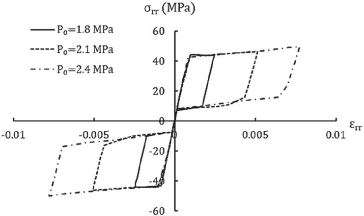
Figure 6 Stress-strain response of the mid-radial annular plate grid point along r-axis for the time period of 0.005 s sand various pressure amplitudes.
Figure 7 represents the martensitic volume fraction of plate against time for the time period of 0.005 s and different values of . As can be seen, the martensitic volume fraction enhances by increasing the value of , resulting in a softened material.
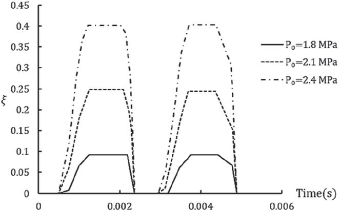
Figure 7 Variation of martensitic volume fraction versus time in mid-radial annular plate grid point for the time period of 0.005 s and various pressure amplitudes.
Figure 8 represents Young’s modulus-time graph for the mid-radial annular plate grid point. As can be seen, Young’s modulus decreases with the rise in the pressure, leading to reduced material strength.
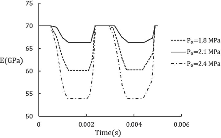
Figure 8 Variation of Young’s modulus versus time in mid-radial annular plate grid point for the time period of 0.005 s and various pressure amplitudes.
Furthermore, as an example, the frequency response of the nonlinear system is plotted in Figure 9 over the frequency interval of 185–210 Hz, which contains one natural frequency of the plate at the pure austenitic phase, 196.2 Hz. According to Figure 9, the response peaks shifted leftward with respect to the linear system natural frequencies. This shift becomes greater as the pressure amplitude increases.
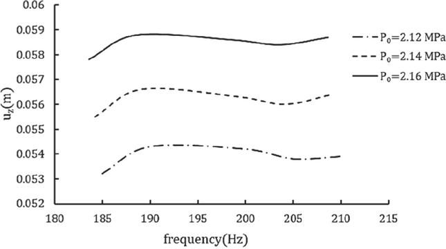
Figure 9 Frequency response diagrams of the nonlinear system for various pressure amplitudes.
6 Conclusion
The present study aimed to investigate the free and forced vibration of an SMA annular sector plate. The pseudoelastic behavior of the SMA annular sector plate was simulated using the Boyd-Lagoudas constitutive model. Hamilton’s principle and the first-order shear deformation plate theory were used to determine the governing equations of motion. The DQM method was used to determine the annular sector plate’s natural frequencies. Accordingly, DQM, Newmark, and SMA codes were utilized to solve the equation of motion, and the dynamic response of the plate under harmonic load was determined. The results were obtained free and forced vibration. Then, the analysis of the SMA plate was validated with the present research and FEM (ABAQUS software), which indicated good accuracy. Finally, the transverse displacement of the plate for different angles under the corresponding phase transformation pressure was provided, and the influences of the applied pressure range on the martensitic volume fraction, transverse displacement, and Young’s modulus were tabulated for a particular case with . The following results were obtained.
1. When the pressure increases sufficiently, a phase transformation occurs in the material, in which case the martensitic volume fraction becomes a non-zero value. Also, increasing the pressure leads to increasing the amount of vibration amplitude and decreasing the Young’s modulus and strength of the material.
2. The linear natural frequency declined with the rise in the angle of the sector.
3. Increasing the angle leads to increased transverse displacement of the sector plate.
4. When the applied pressure caused phase transformation in the material, the martensitic volume fraction increases and the material exhibits nonlinear behavior. Also, softening behavior is observed in the material.
5. The results showed that the proposed method had high accuracy and speed to predict the vibrational behavior of the sector plate with respect to the nonlinear effects of the material due to the phase transformation.
6. The resonance points of the nonlinear system (with phase transformation) shifted to the left compared to the linear system (without phase transformation), and their frequency is less than the normal frequencies of the linear system.
Funding
This research received no specific grant from any funding agency in the public, commercial, or not-for-profit sectors.
Conflict of Interest
The authors declare no conflict of interest in preparing this article.
References
[1] Lagoudas, DC. Shape memory alloys. Modeling and engineering applications. New York: Springer, 2008.
[2] Park JS, Kim JH, Moon SH. Vibration of thermally post-buckled composite plates embedded with shape memory alloy fibers. Composite Structures 2004; 63(2):179–188. https://doi.org/10.1016/S0263-8223(03)00146-6
[3] Du XW, Sun G, Sun SS. A study on the deflection of shape memory alloy (SMA) reinforced thermo-viscoelastic beam. Composites Science and Technology 2004; 64(9):1375–1381. https://doi.org/10.1016/j.compscitech.2003.10.020
[4] Hashemi SM, Khadem SE. Modeling and analysis of the vibration behavior of a shape memory alloy beam. International Journal of Mechanical Sciences 2006; 48(1):44–52. https://doi.org/10.1016/j.ijmecsci.2005.09.011
[5] Saidi AR, Baferani AH, Jomehzadeh E. Benchmark solution for free vibration of functionally graded moderately thick annular sector plates. Acta Mechanica 2011; 219(3):309–335. https://doi.org/10.1007/s00707-011-0459-1
[6] Hejripour F, Saidi AR. Nonlinear free vibration analysis of annular sector plates using differential quadrature method. Proceedings of the Institution of Mechanical Engineers, Part C: Journal of Mechanical Engineering Science 2012; 226(2):485–497. http://doi.org/10.1177/0954406211414517
[7] Asadi H, Bodaghi M, Shakeri M, Aghdam MM. An analytical approach for nonlinear vibration and thermal stability of shape memory alloy hybrid laminated composite beams. European Journal of Mechanics-A/Solids 2013; 42:454–468. https://doi.org/10.1016/j.euromechsol.2013.07.011
[8] Asemi K, Salehi M, Sadighi M. Three dimensional static and dynamic analysis of two dimensional functionally graded annular sector plates. Structural Engineering and Mechanics: An International Journal 2014; 51(6):1067–1089.
[9] Volkov AE, Evard ME, Red’kina KV, Vikulenkov AV, Makarov VP, Moisheev AA, Markachev NA, Uspenskiy ES. Simulation of payload vibration protection by shape memory alloy parts. Journal of Materials Engineering and Performance 2014; 23(7):2719–2726. https://doi.org/10.1007/s11665-014-1084-7
[10] Forouzesh F, Jafari AA. Radial vibration analysis of pseudoelastic shape memory alloy thin cylindrical shells by the differential quadrature method. Thin-Walled Structures 2015; 93:158–168. https://doi.org/10.1016/j.tws.2015.03.022
[11] Auricchio F, Constantinescu A, Menna C, Scalet G. A shakedown analysis of high cycle fatigue of shape memory alloys. International Journal of Fatigue 2016; 87:112–123. https://doi.org/10.1016/j.ijfatigue.2016.01.017
[12] Ashrafi MJ, Ghaffari I, Elahinia M, Nematollahi MR. Nonlinear free vibration and damping analysis of a microbeam with pseudoelastic shape memory alloy layer based on the modified couple stress theory. Journal of Vibration and Control, 27(7–8), 957–968. http://doi.org/10.1177/1077546320935284
[13] Adeodato A, Duarte BT, Monteiro LL, Pacheco PM, Savi MA. Synergistic use of piezoelectric and shape memory alloy elements for vibration-based energy harvesting. International Journal of Mechanical Sciences 2021 Mar 15; 194:106206. https://doi.org/10.1016/j.ijmecsci.2020.106206
[14] Nasrollah Barati AH, Etemadi Haghighi AA, Haghighi S, Maghsoudpour A. Free and forced vibration analysis of shape memory alloy annular circular plate in contact with bounded fluid. Iranian Journal of Science and Technology, Transactions of Mechanical Engineering 2022:1–6. https://doi.org/10.1007/s40997-021-00477-7
[15] Tabrizikahou A, Kuczma M, Łasecka-Plura M, Farsangi EN, Noori M, Gardoni P, Li S. Application and modelling of shape-memory alloys for structural vibration control: State-of-the-art review. Construction and Building Materials 2022 Aug 1; 342:127975. https://doi.org/10.1016/j.conbuildmat.2022.127975
[16] Barati AHN, Jafari AA, Haghighi SE, Maghsoudpour A. Dynamic response of an annular circular plate made of shape memory alloy using differential quadrature method. Proceedings of the Institution of Mechanical Engineers, Part C: Journal of Mechanical Engineering Science 2022 Jun; 236(11):5836–5849. https://doi.org/10.1177/09544062211062764
[17] Yousefzadeh S, Jafari AA, Mohammadzadeh A. Effect of hydrostatic pressure on vibrating functionally graded circular plate coupled with bounded fluid. Applied Mathematical Modelling 2018; 60:435–46. https://doi.org/10.1016/j.apm.2017.11.009
[18] Bert CW, Malik M. Differential quadrature method in computational mechanics: A review. Appl. Mech. Rev. 1996; 49(1):1–28. https://doi.org/10.1115/1.3101882
[19] Shu C. Differential quadrature and its application in engineering. New York: Springer, Science & Business Media, 2012.
[20] Reddy JN. An introduction to nonlinear finite element analysis: With applications to heat transfer, fluid mechanics, and solid mechanics. Oxford: OUP, 2014.
Biographies

Amir Hossein Nasrollah Barati is an Assistant Professor of Mechanical Engineering at the Aligudarz Branch of Islamic Azad University, Iran. His research interests include mechanical vibration and control.

Reza Shahveh is a Lecturer in Mechanical Engineering at the Aligudarz Branch of Islamic Azad University, Iran. His research interests include mechanical vibration and semianalytical methods in engineering.
European Journal of Computational Mechanics, Vol. 34_6, 471–498
doi: 10.13052/ejcm2642-2085.3462
© 2026 River Publishers