Research on Three-dimensional Vibration Control of Frame-shear Wall Structure with New 3DVEDC Bearing
Xiaohui Wu*, Hantuo Dong and Yanfeng Wang
Power Grid Planning Research Center of Guangdong Power Grid Co. Ltd., Guangzhou 510220, China
E-mail: 13570133334@139.com
*Corresponding Author
Received 04 May 2025; Accepted 19 July 2025
Abstract
The dynamic response of a frame-shear wall building is studied under both vertical and horizontal excitations. To reduce the structural response and control the dynamic amplification factor induced by vibration inputs, a new type of three-dimensional vibration and earthquake dual control (3DVEDC) bearing is proposed. The control effect of the 3DVEDC bearing on the dynamic response of the frame-shear wall structure is investigated. The key technical indicators, such as response spectrum, peak and root-mean-square acceleration, are compared and analyzed for the controlled and uncontrolled structure based on simulation and shaking table test. The effectiveness of the 3DVEDC bearing is further verified in earthquakes. The result shows that the proposed 3DVEDC bearing has a bidirectional decoupling function for vertical and horizontal vibration control. The dynamic response under both vertical and horizontal excitations is effectively controlled by the 3DVEDC bearing. The control effect of the top root-mean-square accelerations of the controlled structure reaches 89.46%. The main frequency range of 1.53.5 Hz of the structure with control is far from the main frequency of the earthquake waves. The seismic control capability is further verified using a shaking table test and the maximum control effect reaches 59.08% in the earthquake.
Keywords: Frame-shear structure, three-dimensional vibration control, 3DVEDC bearing, control effect, shaking table test.
1 Introduction
With the rapid development of urban rail transit and the increasing proximity of industrial and civil equipment to living areas, the continuous vibration generated by the service of the track or equipment induces a vertical dynamic response of adjacent building structures, causing excessive structural vibration and secondary noise [1, 2]. Although the vibration generated by the operation of tracks or equipment belongs to the micro-vibration range, long-term vibration excitation not only affects the fatigue effect of buildings, especially key connection nodes, but also causes irreversible damage to physiological and psychological health [3]. Therefore, it is necessary to conduct predictive research on the vibration propagation law and vibration response of buildings under vertical excitation and adopt effective control technology to improve the quality of daily production and life.
The vibration response of the overlying building induced by subway operation will not cause structural damage, but it has a significant impact on personnel and precision instruments [4]. Based on the analysis of measured vibration data of adjacent buildings of the subway, it can be found that the larger vibration occurs between 5 Hz and 50 Hz, with low being the main frequency [5]. Zhang et al. found that the vibration response of columns, beams and walls with higher stiffness in building structures is smaller than that of the lower stiffness [6]. The vibration response of the floor is about 5 times than that of the beam. The peak frequency domain of secondary noise is in the range 50–80 Hz. The main factors affecting the amplification of vertical vibration along the height direction include factors such as the weight and height of the building [7, 8]. The vibration response of each floor of heavy buildings will decrease with the increase in the number of floors. However, the vibration response of each floor of lightweight buildings is mainly low-order vibration, and the dynamic response induced by vibration shows a gradually increasing trend along the height of the building [9].
In recent decades, isolation technologies represented by rubber isolation have developed rapidly in countries such as China and Japan [10, 11]. The conventional isolation technology is base isolation, which is mainly aimed at horizontal earthquakes, with significant isolation effects but weak control effects on vertical earthquakes or vibrations [12]. In response to the current problem of difficulty in effectively solving the vertical dynamic response induced by vibration, domestic and foreign scholars have actively carried out the research and development of three-dimensional vibration-seismic dual control technology devices [13, 14]. Gu et al. designed a curved beam to lower the center of gravity of the upper structure (spiral spring) for a three-dimensional isolation bearing composed of spiral springs and laminated rubber [15]. Zhang found that thick-layer rubber three-dimensional isolation bearings have stable horizontal mechanical properties [16]. When the first shape coefficient is below 4, three-dimensional isolation can be achieved. For the construction engineering areas of the thick-layer rubber isolation bearings, Zhou et al. designed a thick-layer rubber isolation system for a two-story acoustic laboratory, with a vertical frequency of 5 Hz [17]. To improve the vertical isolation performance of thick rubber isolation systems for key equipment vibration problems in nuclear power plants, the first shape coefficient is approximately 3–6 or lower [18]. Disc spring isolation systems are designed for the vibration isolation problem [19, 20]. The research on disc spring isolation systems mainly focuses on finite element simulation [21]. In addition, quasi-zero stiffness isolation system for vertical isolation is designed based on disc springs and linear compression springs [22, 23].
This research conducts a study on the dynamic response of frame-shear wall building under both vertical and horizontal excitations. In order to achieve a good three-dimensional vibration control effect, a new type of three-dimensional vibration and earthquake dual control (3DVEDC) bearing, that can simultaneously attenuate vertical and horizontal vibrations, is proposed and the corresponding constitutive relationship model is derived. The control effect of the 3DVEDC bearing on the dynamic response of the structure is investigated, and technical indicators such as vertical acceleration time history, response spectrum, peak acceleration, and root-mean-square acceleration, are compared and analyzed for the controlled and uncontrolled structure. The effectiveness of the 3DVEDC bearing is further verified using a shaking table test in vibration and earthquake excitations.
2 Proposal of the New 3DVEDC Bearing
2.1 Structural Construction
A new type of three-dimensional vibration and earthquake dual control bearing (3DVEDC bearing) is proposed, as shown in Figure 1. The new 3DVEDC bearing is composed of two parts: modular cylindrical spiral spring and laminated lead core rubber. The vertical vibration control effect is achieved by the modular cylindrical spiral spring. The horizontal shock absorption control effect is jointly undertaken by the cylindrical spiral spring and laminated lead rubber. Among them, the cylindrical spiral spring mainly plays a role in providing horizontal lateral stiffness, while the laminated lead rubber mainly plays a role in horizontal energy dissipation.
The lower end of the cylindrical spiral spring and laminated lead rubber is fixed on the lower connecting steel plate of the 3DVEDC bearing. The upper end of the cylindrical spiral spring is fixed to the upper connecting steel plate, while the upper end of the lead core rubber device is inserted into the cylinder steel sleeve of the upper connecting plate. Under vertical excitation, the modular cylindrical spiral spring provides frequency modulation and vibration reduction effects, and the laminated lead core rubber does not work. Under horizontal seismic action, the cylindrical spiral springs and laminated lead core rubber work together to achieve a shock absorption control effect. Therefore, the horizontal and vertical vibration reduction functions of the 3DVEDC bearing are independent of each other, achieving bidirectional decoupling control under the effects of vibration and earthquake.
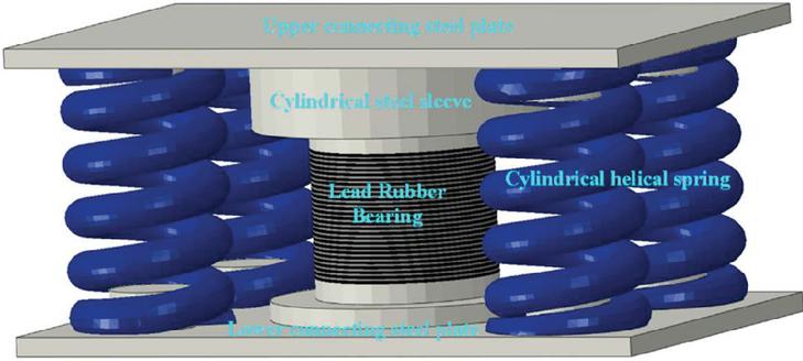
Figure 1 3DVEDC bearing.
2.2 Mechanical Constitutive
2.2.1 Vertical mechanical constitutive
It can be seen that the vertical mechanical performance of the 3DVEDC bearing is only provided by the cylindrical spiral springs. If the 3DVEDC bearing is composed of cylindrical spiral springs in parallel, the vertical stiffness calculation formula is:
| (1) |
where D is the spring diameter, n is the effective number of turns of the spring, G is the shear modulus of the spring and d is the diameter of the circular cross-section of the spring.
The vertical constitutive supported by 3DVEDC bearing is a linear elastic model, as shown in Figure 2(a). It can be seen that the vertical natural frequency of the vibration reduction system can be expressed as:
| (2) |
where is the equivalent mass, which refers to the comprehensive value of the mass of the entire damping system, , in which is the mass conversion coefficient, which is related to the type of spring. The of the cylindrical coil spring is usually taken as 0.33 [24]. Due to the relatively small mass compared to the structural mass , is taken to simplify the calculation. The vertical mechanical model of the 3DVEDC bearing is linear elasticity, and the Equation (3) can be simplified as:
| (3) |
where S is the vertical static displacement and g is the acceleration due to gravity, taken as 9800 mm/s. It can be seen that the vertical natural frequency is determined by the vertical static displacement S.
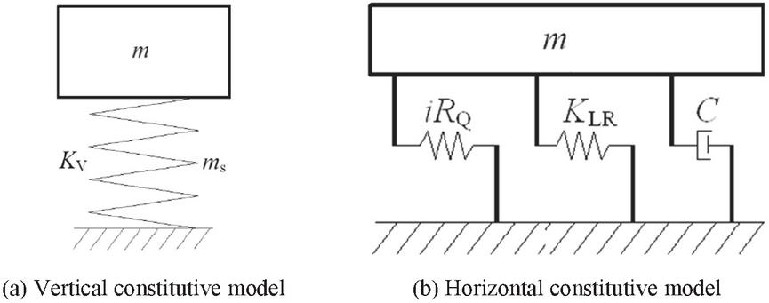
Figure 2 Computational models of the 3DVEDC bearing.
2.2.2 Horizontal mechanical constitutive
The horizontal mechanical performance of the 3DVEDC bearing is determined by the horizontal mechanical performance of both the cylindrical spiral spring and the lead rubber, and its horizontal calculation model is shown in Figure 2(b). is the horizontal shear stiffness of the spring, is the number of the spring, represents all horizontal stiffness of the lead rubbers, including initial stiffness and post-yield stiffness . C represents the damping of the plastic energy dissipation of the rubber. A double-line mechanical model is adopted to characterize the horizontal constitutive relationship of the 3DVEDC bearing. Therefore, the horizontal initial stiffness can be expressed as:
| (4) |
The yield force and post-yield stiffness can be expressed as:
| (5) | |
| (6) |
where and are constant coefficient. X is the amplitude of horizontal shear displacement. The equivalent stiffness is the secant stiffness of the displacement amplitude point of the displacement load curve for each cycle, which can be expressed as:
| (7) |
The equivalent damping ratio is the main parameter that reflects the energy dissipation and seismic reduction effect. The equivalent damping ratio can be calculated by the energy method:
| (8) |
3 Control Design of the Frame-Shear Wall Structure
3.1 Model Establishment and Structural Control Scheme
The height of the frame structure is 27.5 m with eight floors. The first floor is 3 m high, while all others are 3.5 m. The plan size is 45 22 m. The column section is 750 750 mm, the beam section is 250 600 mm, the shear wall thickness is 250 mm. The concrete grade is C40, with an elastic modulus of 32,500 N/mm. The infill wall adopts pressurized and aerated lightweight concrete wall panels. A three-dimensional finite element model was built. Line elements were used for beams and columns, while membrane elements were used for floors. The infill walls were applied in the form of line loads to the primary and secondary beams. The three-dimensional model is shown in Figure 3(a). Table 1 presents the comparison data of the first six modals calculated by two software. It can be seen that the results obtained by the two software are very similar, with a maximum error of only 2.99%, which verifies the effectiveness of the numerical model.
Table 1 Comparison of the first six modals based on two software platforms
| Modal | 1st | 2nd | 3rd | 4th | 5th | 6th |
| ETABS platform | 0.694 | 0.649 | 0.615 | 0.525 | 0.511 | 0.478 |
| SAUSAGE platform | 0.706 | 0.669 | 0.629 | 0.563 | 0.520 | 0.484 |
| Error | 1.70% | 2.99% | 2.23% | 1.50% | 1.73% | 1.24% |
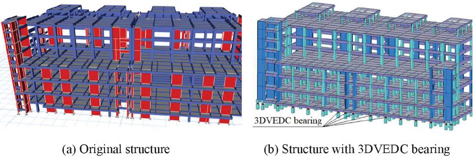
Figure 3 Structural 3D finite element model.
The proposed 3DVEDC bearing is then designed at the bottom of the structure. A total of 167 sets of the 3DVEDC bearing are designed, as shown in Figure 3(b). Each set of the 3DVEDC bearing includes six spring components and one rubber isolation component. The spring adopts a modular design, that is, all springs adopt a unified design parameter, namely: free height is 275 mm, axial stiffness 3.139 kN/mm, static load deformation 40 mm, static load 125.6 kN, lateral stiffness 1.595 kN/mm and lateral displacement limit 40 mm. The rubber component adopts G4 type rubber, with an equivalent stiffness of 2.058 kN/mm, elastic stiffness of 128.466 kN/mm, yield force of 51.726 kN and post-yield stiffness ratio of 0.00157. After adopting the control scheme of the 3DVEDC bearing, the first natural period of the frame-shear wall building is extended from 0.694 s to 1.739 s, which is 2.51 times extended.
3.2 Input of Excitation Wave
3.2.1 Vertical excitation wave
A low-frequency voltage type accelerometer, DH8303 dynamic signal testing, and corresponding analysis system are adopted for data collection. The sampling frequency is 1000 Hz, which can cover the high-frequency components of site vibration. Vibration measurement is divided into two types of measurement points: surface measurement points and 8 m underground measurement points (pile foundation embedded position). For underground measurement points, the accelerometer is first placed into a drilled hole and then the sensor in the predetermined position. After that, the drilled hole is poured with concrete. After the concrete has hardened, relevant vibration testing works can be carried out [25, 26].
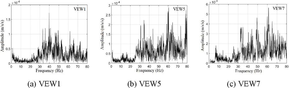
Figure 4 Spectrum of the vibration excitation waves (VEW).
Fifteen vibration waves were measured at the site where the structure is located for both the day and night. After comprehensive comparison, seven representative waves that can reflect the site vibration situation were selected, namely four surface waves (VEW1VEW4) and three underground waves (VEW5VEW7). Figure 4 shows the frequency spectrum of VEW1 and VEW5, while the other vibration waves are similar. The core frequency band of the waves is mainly concentrated in the range 30–80 Hz. It can be observed that, after being filtered by the soil, the high-frequency part (65–80 Hz) of the waves reaching the ground surface is reduced, while the low-frequency part (0–25 Hz) is basically the same.
3.2.2 Horizontal excitation wave
The seismic fortification intensity of the location where the structure is located is 8-degree (0.2 g), the earthquake group is the second group, the site category is Class II, and the site characteristic period is 0.4 s. According to the specifications, one artificial wave (AW1) and two natural waves (NW1, NW2) are selected for seismic motion time history analysis. The names of the seismic waves are ArtWave-RH2TG040 (AW1), Borrego Mtn_NO40 (NW1) and Whittier Narrows-01-NO618 (NW2). According to the specifications, the inputs of the peak ground acceleration (PGA) are 200 gal and 400 gal, respectively, for the moderate and rare earthquake in seismic fortification of 8-degree (0.2 g).
4 Vibration Control Analysis Based on Numerical Simulation
4.1 Analysis of Structural Vertical Vibration Control
4.1.1 Control effect of the vertical dynamic response
Acceleration time history response and its peak and root-mean-square parameters are introduced to investigate the vertical control effect. The root-mean-square acceleration is the effective value of the vibration acceleration in a certain direction within time T, and the calculation formula is:
| (9) |
where is the unweighted vibration acceleration time history within a certain frequency band, is the measurement duration and is the effective value of the root-mean-square acceleration in that frequency band. The root-mean-square acceleration index has statistical significance, which is widely used in practical engineering design [27].
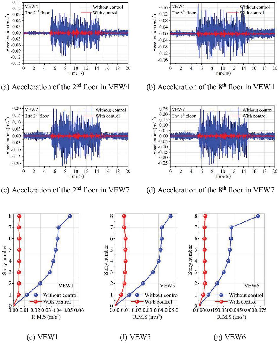
Figure 5 Time history of acceleration responses and root-mean-square along height.
Figure 5 shows the vertical acceleration response time history series of the 2nd and 8th floors, and the variation curves of the vertical root-mean-square acceleration along the height of controlled and uncontrolled structures under different vibration waves. It can be found that the vertical dynamic response is greatly reduced by designing the 3DVEDC bearing at the bottom. It can be considered that the 3DVEDC bearing can effectively control the vertical response. Under the vibration waves of VEW4, VEW6 and VEW7, the peak acceleration of the 8th floor of the structure without control device is 0.182 m/s, 0.271 m/s and 0.268 m/s, respectively. When the control device is designed, the peak acceleration of the 8th floor is 0.025 m/s, 0.035 m/s and 0.034 m/s, respectively. The vertical control effect reaches 86.30%, 87.02% and 87.02%, respectively. It can also be seen that the control effect of the root-mean-square acceleration is similar to the peak acceleration. Under the excitation of VEW1, VEW5 and VEW6, the root-mean-square acceleration of the 8th floor without vibration control is 0.0518 m/s, 0.051 m/s and 0.0721 m/s, respectively. When the vibration control is designed, the root-mean-square acceleration of the 8th floor with vibration control is 0.0055 m/s, 0.0085 m/s and 0.0076 m/s, respectively. The vertical control effect of the root-mean-square acceleration reaches 89.38%, 83.33% and 89.46%, respectively.
Based on the previous section, it can be seen that the peak value and root-mean-square acceleration of the structure gradually increase with the increase of height, and the growth rate accelerates when reaching the 7th floor. By installing the 3DVEDC bearing, not only is the vertical vibration response effectively suppressed, but also the amplification effect of the vibration response along the height can be controlled. The acceleration response shows an overall vibration trend along the height, and there is no amplification effect. For example, under the action of VEW1, the root-mean-square acceleration of the 2nd, 4th, 6th and 8th floors of the structure with control is 0.0052 m/s, 0.0054 m/s, 0.0055 m/s and 0.0055 m/s, respectively. Similarly, under the action of VEW6, the root-mean-square acceleration of the 2nd, 4th, 6th and 8th floors of the structure with control is 0.0069 m/s, 0.0070 m/s, 0.0072 m/s and 0.0076 m/s, respectively. Therefore, by installing 3DVEDC, the vertical vibration characteristics of the structure have been greatly changed. The phenomenon of vertical vibration gradually increasing along the height of the uncontrolled structure has transformed into a phenomenon of overall vibration along the height. It can be considered that the vibration comfort of the structure under vertical excitation waves is greatly improved, improving the vibration usage environment of the building.
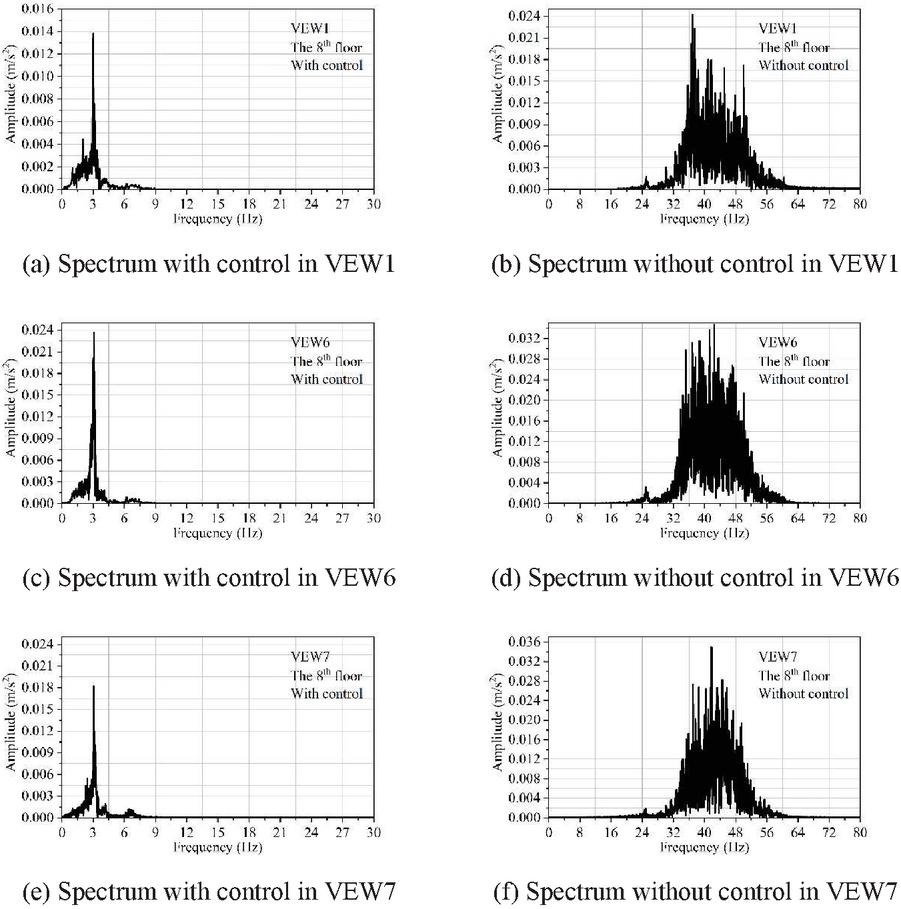
Figure 6 Acceleration spectrum of the top story in VEW1, VEW6 and VEW7.
4.1.2 Acceleration response spectrum
Figure 6 shows a comparison of the acceleration response spectra of the top floor of the structure under the action of vibration waves VEW4, VEW6 and VEW7. It can be observed that for the uncontrolled structure without 3DVEDC bearing, the top acceleration response spectrum is mainly concentrated in the frequency range of 3256 Hz, which is within the main frequency range of the input vibration wave (40–70 Hz). This phenomenon indicates that the uncontrolled structure exhibits resonance under vertical vibration excitations, resulting in a significant vibration response of the structure, and the amplification effect is obvious with increasing height. However, it can be found that for the controlled structure with 3DVEDC bearing, the top acceleration response spectrum is mainly concentrated in the frequency range of 1.53.5 Hz. This frequency band is not only far from the main frequency band of the input vibration wave, but also much lower than the main frequency band of the acceleration response spectrum of the top floor of the uncontrolled structure. This phenomenon indicates that the controlled structure will not experience resonance under vertical vibration excitations. Therefore, the vertical vibration response of the controlled structure is much lower than that of the uncontrolled structure. It can be demonstrated that designing the 3DVEDC bearing at the structural base can play a good filtering role, greatly reducing the risk of vibration-induced physiological and psychological discomfort in the human body. In addition, it can be seen that, compared to the uncontrolled structure, the controlled structure not only has a smaller main frequency and narrower coverage range of the top-level acceleration response spectrum but also has a smaller amplitude of the acceleration spectrum, further verifying that the vertical dynamic response of the controlled structure is much smaller.
Table 2 Comparison of the first six modals based on two software platforms
| Without Control | With Control | |||||||||
| Story | Control | |||||||||
| Direction | No. | AW1 | NW1 | NW5 | Envelope | AW1 | NW1 | NW5 | Envelope | Effect |
| X-direction | 8 | 6316 | 6888 | 6393 | 6888 | 4788 | 5102 | 4482 | 5102 | 25.92% |
| 7 | 7928 | 9401 | 8635 | 9401 | 3911 | 3958 | 3384 | 3958 | 57.89% | |
| 6 | 9350 | 11173 | 10692 | 11173 | 1586 | 1898 | 1288 | 1898 | 83.01% | |
| 5 | 10798 | 11836 | 12397 | 12397 | 2722 | 2689 | 2814 | 2814 | 77.30% | |
| 4 | 12138 | 11318 | 13904 | 13904 | 5378 | 5807 | 5396 | 5807 | 58.23% | |
| 3 | 13520 | 13090 | 15185 | 15185 | 7962 | 8601 | 7703 | 8601 | 43.36% | |
| 2 | 14532 | 14258 | 15597 | 15597 | 10548 | 11109 | 9792 | 11109 | 28.78% | |
| 1 | 15038 | 15138 | 15838 | 15838 | 12901 | 13232 | 11527 | 13232 | 16.46% | |
| Y-direction | 8 | 5722 | 5788 | 5356 | 5788 | 2686 | 3238 | 2848 | 3238 | 44.05% |
| 7 | 7032 | 7977 | 7280 | 7977 | 2195 | 2918 | 2058 | 2918 | 63.41% | |
| 6 | 7566 | 9516 | 8966 | 9516 | 4810 | 4988 | 3843 | 4988 | 47.58% | |
| 5 | 8786 | 9962 | 10469 | 10469 | 7076 | 6260 | 6029 | 7076 | 32.41% | |
| 4 | 9955 | 9266 | 11617 | 11617 | 7814 | 7044 | 7001 | 7814 | 32.74% | |
| 3 | 11143 | 10550 | 12326 | 12326 | 8218 | 7451 | 7497 | 8218 | 33.33% | |
| 2 | 12037 | 11608 | 12778 | 12778 | 9371 | 8441 | 8426 | 9371 | 26.66% | |
| 1 | 12492 | 12362 | 13068 | 13068 | 11354 | 9985 | 9962 | 11354 | 13.11% |
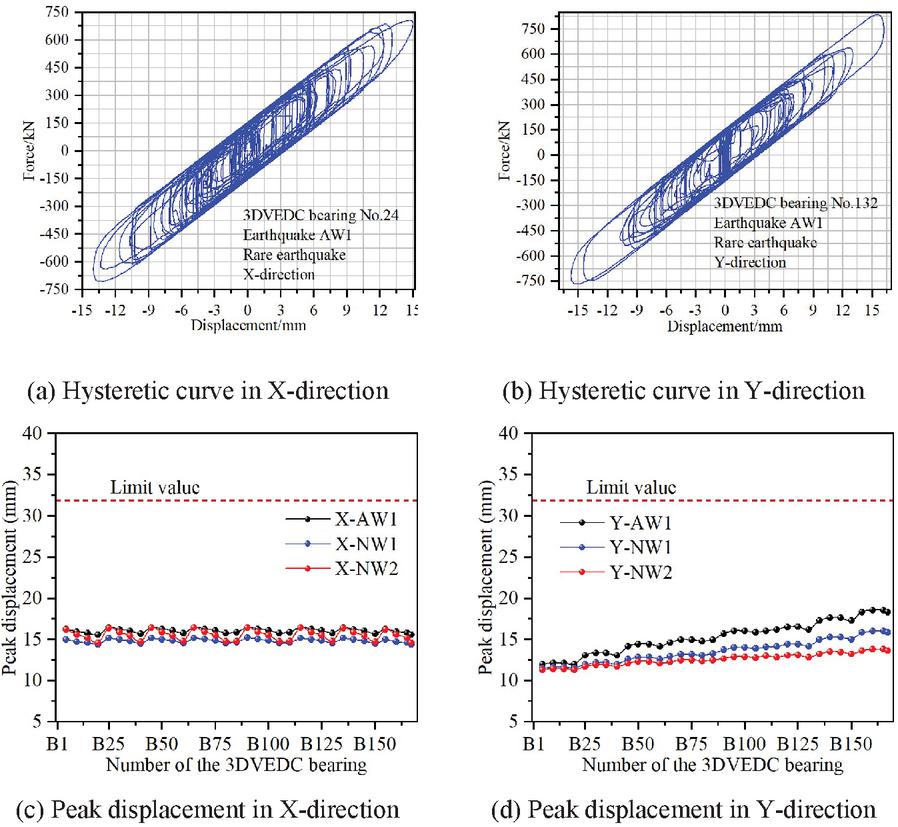
Figure 7 Hysteretic curve and peak displacement of the 3DVEDC bearing in an earthquake.
4.2 Analysis of structural horizontal seismic control
Table 2 shows a comparison of the story shear force between the structures with and without control in moderate earthquakes. It can be seen that by designing 3DVEDC bearings at the bottom of the structure, not only can the dynamic response of the structure under vertical vibration excitation be reduced but also the seismic response of the structure under horizontal earthquake action can be effectively reduced. The maximum damping control effects in the X- and Y-directions of the structure under moderate earthquakes reached 83.01% and 63.41%, respectively. This damping control effect under horizontal seismic action is mainly attributed to the laminated lead core rubber in the 3DVEDC bearing. Under earthquake action, the laminated lead core rubber has shown good energy dissipation effect, effectively absorbing the energy input into the upper structure of seismic motion and attenuating the seismic response of the structure. The hysteresis curve of representative 3DVEDC bearings under rare earthquakes is shown in Figures 7(a,b).
In addition, horizontal displacement of the 3DVEDC bearings is a major technical indicator for determining their normal function under horizontal seismic action. Especially under rare earthquakes, the spring assembly of the 3DVEDC bearings should not exceed the displacement limit value so as to ensure that the bearing does not fail prematurely under seismic action. Peak displacement of the 3DVEDC bearings in rare earthquakes and corresponding comparison with the limit value are shown in Figures 7(c,d). It can be seen that the maximum horizontal displacement of the spring components in the X- and Y-directions of the 3DVEDC bearing under rare earthquakes is 16.41 mm and 18.56 mm, respectively, and both are under the action of artificial wave AW1. It can be concluded that the maximum horizontal displacement of the spring in both directions is lower than that of the limit value of 32 mm [28], indicating that the 3DVEDC bearing will not fail prematurely under rare earthquake conditions.
Table 3 Similar relationship of the geometric and physical parameters
| Parameter Name | Similarity Ratio | Similarity Coefficients | Similarity Ratio |
| Geometric | 1/20 | Stress | 1/2.5 |
| Modulus of elasticity | 1/2.5 | Force | 1/1000 |
| Acceleration response | 2 | Strain | 1 |
| Quality | 1/2000 | Stiffness | 1/36 |
| Time | 0.1826 | Damping ratio | 1 |
| Frequency | 5.4772 | Density | 5.333 |
| Displacement | 1/20 | Speed | 0.2738 |
Table 4 Total stiffness of the control layer for original and scaled models
| Item | Vertical | Horizontal |
| Total stiffness of the original model | 296663 N/mm | 148332 N/mm |
| Similarity coefficients | 1/36 | 1/36 |
| Theoretical stiffness of the scaled model (A) | 8229 N/mm | 4115 N/mm |
| Actual stiffness of the scaled model (B) | 9125 N/mm | 4563 N/mm |
| Error ((B-A)/B) | 9.82% | 9.82% |
5 Vibration Control Analysis Based on Shaking Table Test
5.1 Model Design
In order to further confirm the vertical vibration control effect and horizontal vibration safety of the proposed 3DVEDC bearing, this section conducts research on the horizontal and vertical control effects based on shaking table test. Based on similar physical, geometric and boundary conditions, a scaled testing model with a scale ratio of 1:20 is designed and the corresponding similar relationship for the geometric and physical parameters is shown in Table 3. According to the design parameters of the 3DVEDC bearing in the previous sections, the control parameters of the scaled model are designed based on stiffness equivalence (see Table 4), showing that the error between theoretical and actual stiffness is only 9.82%. The 167 3DVEDC bearings at the bottom of the original structure are equivalent to six scaled 3DVEDC bearings at the bottom of the scaled testing model, and the parameters of each of the scaled 3DVEDC bearing are shown in Table 5.
Table 5 Parameter design of the six scaled 3DVEDC bearings
| Vertical | Static | Vertical | Horizontal | |
| Name | Capacity | Deformation | Stiffness | Stiffness |
| 3DVEDC-1 | 38.76 kN | 20 mm | 1938 N/mm | 969 N/mm |
| 3DVEDC-2 | 27.88 kN | 20 mm | 1394 N/mm | 697 N/mm |
| 3DVEDC-3 | 27.72 kN | 20 mm | 1386 N/mm | 693 N/mm |
| 3DVEDC-4 | 37.15 kN | 20 mm | 1857 N/mm | 929 N/mm |
| 3DVEDC-5 | 25.37 kN | 20 mm | 1268 N/mm | 634 N/mm |
| 3DVEDC-6 | 25.62 kN | 20 mm | 1281 N/mm | 641 N/mm |
Based on the geometric similarity ratio of 1/20, the geometric dimension of the scaled testing model is 3.84 1.93 1.63 m, as shown in Figure 8. Particle concrete with elastic modulus of 13400 N/mm is adopted for the scaled testing model. The floor weight of the scaled testing model calculated based on the scaling theory does not meet the weight equivalent requirements. Thus, before testing, corresponding counterweights need to be added to the model floors according to the principle of weight similarity. The total weight of the scaled model with the counterweights is 18.3088 t, and the theoretical design weight of the scaled model is 17.7805 t, with 2.75% difference between the two.
Using white noise as input, the dynamic characteristics of the scaled test model can be tested. For the uncontrolled scaled testing model, namely without the 3DVEDC bearings, the first- and second-order test frequencies are 5.92 Hz and 7.62 Hz, respectively, while the theoretically calculated first- and second-order frequencies of the model are 6.94 Hz and 7.89 Hz, respectively. It can be seen that the errors between the first- and second-order theories of the model and the measured frequency are 14.7% and 2.42%, respectively. For the controlled scale test model, namely with 3DVEDC bearings at the model base, the first test frequency is 3.02 Hz, while the theoretically calculated model has a first frequency of 3.15 Hz, with an error of 3.38% between the two. Therefore, it can be seen that the designed scaled testing model and the corresponding parameters of the control layer are reasonable and feasible.
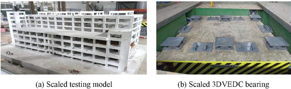
Figure 8 The scaled testing model and 3DVEDC bearing.
5.2 Test Plan Design
5.2.1 Acceleration and displacement sensors
A total of 36 acceleration sensors and 65 strain gauges were arranged. The dynamic responses of each floor of the scaled model were measured by the acceleration sensors. Structural damage can be analyzed through data recorded by strain gauges, which are mainly set at the bottom column, corner column, beam-column nodes and other nodes with high stress. Vibration waves of the VEW4, VEW6, VEW7 and earthquake waves of NW1 are adopted as the excitation waves of the shaking table test. The reason for choosing wave NW1 is that the dynamic response of the structure is the highest under the action of this seismic wave based on the analysis in the previous section. Table 6 shows the testing cases for the shaking table test, in which 24 cases are investigated for the scaled models with and without controls.
| Scaled Model Without Control | Scaled Model With Control | ||||
| Case name | PGA (cm/s) | Wave | Case name | PGA (cm/s) | Wave |
| N-MC1/N-MC2 | 100/130 | VEW4 | I-MC1/I-MC2 | 100/130 | VEW4 |
| N-MC3/N-MC4 | 100/130 | VEW6 | I-MC3/I-MC4 | 100/130 | VEW6 |
| N-MC5/N-MC6 | 100/130 | VEW7 | I-MC5/I-MC6 | 100/130 | VEW7 |
| N-MC7 | 70 | Man-X | I-MC7 | 70 | Man-X |
| N-MC8 | 70 | Man-Y | I-MC8 | 70 | Man-Y |
| N-MC9 | 200 | Man-X | I-MC9 | 200 | Man-X |
| N-MC10 | 200 | Man-Y | I-MC10 | 200 | Man-Y |
| N-MC11 | 400 | Man-X | I-MC11 | 400 | Man-X |
| N-MC12 | 400 | Man-Y | I-MC12 | 400 | Man-Y |
Table 7 Root-mean-square acceleration in vibration waves (unit: cm/s)
| Case Name | Control Effect | |||||||||
| Floor | I-MC1 | I-MC3 | I-MC5 | N-MC1 | N-MC3 | N-MC5 | Correspondingly | Average | ||
| 1F | 0.49 | 0.89 | 0.73 | 2.5 | 3.13 | 3.31 | 80.40% | 71.57% | 77.95% | 76.64% |
| 2F | 0.53 | 0.9 | 0.74 | 2.64 | 3.52 | 4.11 | 79.92% | 74.43% | 82.00% | 78.78% |
| 3F | 0.52 | 0.95 | 0.71 | 2.78 | 4.06 | 4.36 | 81.29% | 76.60% | 83.72% | 80.54% |
| 4F | 0.54 | 1.00 | 0.69 | 3.06 | 4.37 | 4.41 | 82.35% | 77.12% | 84.35% | 81.27% |
| 5F | 0.55 | 0.99 | 0.68 | 3.43 | 4.57 | 4.84 | 83.97% | 78.34% | 85.95% | 82.75% |
| 6F | 0.55 | 1.00 | 0.67 | 3.96 | 5.45 | 4.74 | 86.11% | 81.65% | 85.86% | 84.54% |
| 7F | 0.51 | 0.87 | 0.68 | 4.24 | 5.33 | 5.37 | 87.97% | 83.68% | 87.34% | 86.33% |
| 8F | 0.55 | 0.85 | 0.76 | 4.64 | 6.00 | 5.37 | 88.15% | 85.83% | 85.85% | 86.61% |
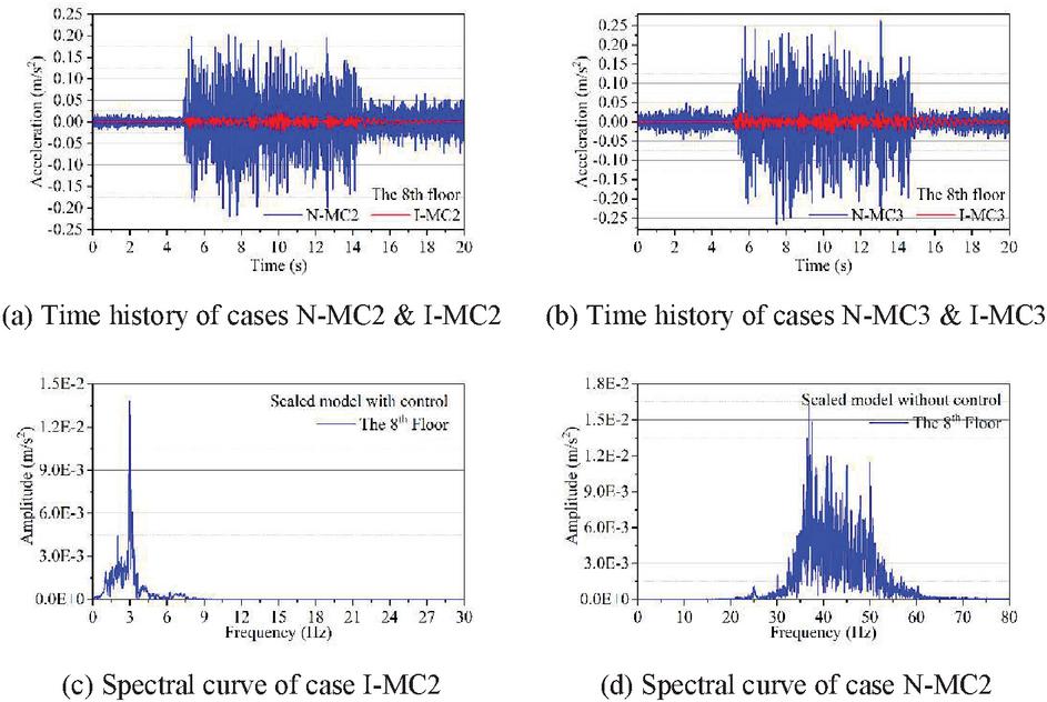
Figure 9 The scaled testing model and 3DVEDC bearing.
5.3 Analysis of Testing Results
5.3.1 Vertical vibration control
Table 7 shows the vertical root-mean-square acceleration and vibration control effects of the scaled testing model under three vibration excitations. Figures 9(a,b) show a comparison of vertical dynamic response time history curves between uncontrolled and controlled structures. It can be seen that after setting up the 3DVEDC bearing, the vertical dynamic response of the model is greatly reduced. The average control effect under three vibration wave excitations is lowest at 76.64% and highest at 86.61%, verifying the effectiveness of the proposed 3DVEDC bearing in vibration control under vertical excitation through vibration table tests. For uncontrolled scaling models, the vertical dynamic response of the structure shows a gradually increasing trend along the height direction. However, after setting up the 3DVEDC bearing, the vertical power box of the structure changes very little along the height direction. For example, for Case N-MC1, the root-mean-square acceleration of the 1st and 8th floors of the structure is 2.5 cm/s and 4.64 cm/s, respectively, amplified by 1.86 times. Correspondingly, for Case I-MC1, the root-mean-square acceleration of the 1st and 8th floors of the structure is 0.49 cm/s and 0.55 cm/s, respectively, only amplified by 1.12 times. In addition, it can be seen that the main frequency band of the uncontrolled model is 30–60 Hz, while the main frequency band of the controlled model is around 3 Hz, as shown in Figures 9(c,d). By setting up the 3DVEDC bearing, the dynamic characteristics of the upper structure can be effectively adjusted away from the core frequency band of external load excitation, thereby greatly reducing the vertical dynamic response of the structure.
Table 8 Root-mean-square acceleration in vibration waves (unit: cm/s)
| Floor | I-MC9 | I-MC10 | N-MC9 | N-MC10 | Control effect | |
| 1F | 14.11 | 15.69 | 28.98 | 28.68 | 51.31% | 45.29% |
| 2F | 19.48 | 18.85 | 36.03 | 34.15 | 45.93% | 44.80% |
| 3F | 22.05 | 27.91 | 39.66 | 45.9 | 44.40% | 39.19% |
| 4F | 23.66 | 38.99 | 44.04 | 56.99 | 46.28% | 31.58% |
| 5F | 24.32 | 39.57 | 46.71 | 63.14 | 47.93% | 37.33% |
| 6F | 25.39 | 41.16 | 48.52 | 70.94 | 47.67% | 41.98% |
| 7F | 26.01 | 41.06 | 57.95 | 78.43 | 55.12% | 47.65% |
| 8F | 28.32 | 42.28 | 69.2 | 86.67 | 59.08% | 51.22% |
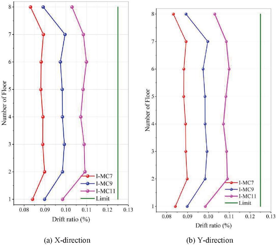
Figure 10 Drift ratio.
5.3.2 Horizontal seismic control
A comparison of the root-mean-square of horizontal acceleration between uncontrolled and controlled model structures under earthquake conditions is shown in Table 8. It can be seen that by setting the 3DVEDC bearing, the acceleration response of the upper structure under earthquake action also has good control effect. The maximum shock absorption effect in the X- and Y-directions of the structure reached 59.08% and 51.22%, respectively. In addition, it can be seen that by setting the 3DVEDC bearing at the bottom of the structure, the upper structure approaches a translational motion trend under earthquake action, such as the inter-story displacement angle of the structure remaining basically unchanged along the height direction, as shown in the Figure 10.
According to GB/T51408-2020 “Design Standard for Seismic Isolation of Buildings”, the limit value of horizontal drift ratio for frame shear wall structures is 1/800. The summary of the drift ratios of each floor in the X- and Y-directions under earthquake action for the controlled model is shown in Figure 10. As shown in Figure 10, the drift ratios of each floor in the X- and Y-directions for the controlled model are all less than 1/800, which verifies the safety of horizontal buildings with spring lead rubber bearings under seismic fortification intensity (seven degrees).
6 Conclusion
This study focuses on the dynamic response and vertical vibration control of a frame-shear wall structure under vertical and horizontal excitations. The conclusions are as follows:
(1) A new type of 3DVEDC bearing is proposed, which has a bidirectional decoupling function for vertical and horizontal vibration control. The constitutive relationship of the 3DVEDC bearing is derived and established in both vertical and horizontal directions.
(2) Peak and root-mean-square accelerations of the structure without control gradually increases with the increase of height. The dynamic amplification coefficients of the root-mean-square acceleration of the top layer reach 3.19 times on average.
(3) By using the 3DVEDC bearing, whether it is excited by surface or underground waves, the dynamic response is attenuated. Compared with the uncontrolled structure, the control effects of the root-mean-square acceleration reach 89.46%. The acceleration response spectrum is mainly concentrated in the frequency range 1.53.5 Hz.
(4) The control effect of the proposed 3DVEDC bearing is further verified using testing, in which the maximum control effect reaches 86.61% under three vibration excitations and 59.08% in the earthquake, verifying the effectiveness of the 3DVEDC bearing.
Funding
This project is supported by the Technology Project of China Southern Power Grid (GDKJXM20230429).
References
[1] G Gao, J Song, G Chen and J Yang. (2015). Numerical prediction of ground vibrations induced by high-speed trains including wheel–rail–soil coupled effects. Soil Dynamics and Earthquake Engineering 77, 274–278. https://doi.org/10.1016/j.soildyn.2015.06.002.
[2] C Mei, D Wang and Y Zhang. (2024). Subway-induced floor vibration predictions in super high-rise multi-tower building located on over-depot based on one-dimensional impedance model. The Structural Design of Tall and Special Buildings 33(12), e2126. https://doi.org/10.1002/tal.2126.
[3] H Fu, Y Chen, Y Yu and M Jin. (2022). Research on hand-transmitted vibration prediction model of the handheld EVA power tool. Applied Sciences 12(20), 10373. https://doi.org/10.3390/app122010373.
[4] Paulo J. Soares, Robert Arcos, Pedro Alves Costa, Kenny F. Conto, Hassan Liravi, Aires Colaço, Alexandre Castanheira-Pinto, Luís Godinho and Joan Cardona (2024). Experimental and numerical study of a base-isolated building subjected to vibrations induced by railway traffic. Engineering Structures 316, 118467. https://doi.org/10.1016/j.engstruct.2024.118467.
[5] W M Yan, H Nie, M Ren, J H Feng, W Zhang and J Q Chen. (2016). In situ experiment and analysis of ground surface vibration induced by urban subway transit. Journal of Railway Science and Engineering 3(2), 1–5.
[6] W Zhang, K Song, K Kang and D Lee. (2025). Numerical analysis of vibration standard conditions of adjacent buildings caused by subway train. KSCE Journal of Civil Engineering 29, 100114. https://doi.org/10.1016/j.kscej.2024.100114.
[7] Y Hua, W Xie and J Xie. (2024). Non-uniform excitation method for predicting railway-induced vibrations of buildings near operational subways. Journal of Building Engineering 84, 108669. https://doi.org/10.1016/j.jobe.2024.108669.
[8] W M Yan, X D Zhang, M Ren and H Nie. (2008). Vertical vibration measurement and analysis of buildings on metro train platforms. Journal of Beijing University of Technology 34(8), 836–841.
[9] P F Li, S Lu, Q G Di and J Y Liu. (2021). Study on the effects of subway vibration on surrounding buildings and damping effect of foundation pit support pile. Railway Investigation and Surveying 47(2), 1–6.
[10] S Cao and J Yi. (2021). Shape memory alloy-spring damper for seismic control and its application to bridge with laminated rubber bearings. Advances in Structural Engineering 24(15), 3550–3563. https://doi.org/10.1177/13694332211033955.
[11] K H Park, Y Fujiwara, T Mazda and Y Kajita. (2020). Evaluation of mechanical properties considering hysteresis characteristic of high damping rubber bearing. Journal of Physics: Conference Series 1687(1), 012019. https://doi.org/10.1088/1742-6596/1687/1/012019.
[12] X Y Hu and Y H Zhu. (2012). Vertical seismic responses of base isolated buildings. Structural Engineers 28(4), 1–6.
[13] W H He, H J Luo, J Xu, W G Liu and D M Feng. (2020). Experimental study and application analysis of mechanical performance of 3D isolation/vibration bearings along railway lines. Journal of Vibration Engineering 33(6), 1112–1121.
[14] H Tsutsumi, H Yamada, K Ebisawa, K Shibata and S Fujimoto. (2001). Shaking table test and dynamic response analysis of 3-D component base isolation system using multi-layer rubber bearings and coil springs. Japan Atomic Energy Research Inst 10(3), 2-10.
[15] Z Gu, Y Lei, W Qian, Z Xiang, F Hao and Y Wang. (2021). An experimental study on the mechanical properties of a high damping rubber bearing with low shape factor. Applied Sciences 11(21), 10059. https://doi.org/10.3390/app112110059.
[16] L L Zhang. (2021). Mechanical properties and vibration reduction effect of the three-dimensional vibration (seismic) isolated device for metro surrounding buildings. Shanghai City: Dissertation of Shanghai University.
[17] Y Zhou, Z Zhang and M F Vassiliou. (2022). Investigation on vertical stiffness reduction of thick rubber bearings under lateral displacement. Construction and Building Materials 360, 129563. https://doi.org/10.1016/j.conbuildmat.2022.129563.
[18] M Abdeli Bisafar and A Manafpour. (2022). Development and experimental validation of a new self-centering HF2V damper with disc springs. Bulletin of Earthquake Engineering 20(13), 7417–7440. https://doi.org/10.1007/s10518-022-01495-9.
[19] X Huang, X Zhou, Y Wang and R Zhu. (2022). Development of resilient friction beams and application to moment-resisting frames. Journal of Building Engineering 45, 103494. https://doi.org/10.1016/j.jobe.2021.103494.
[20] A Q Li and W Wang. (2014). Design of a three-dimensional isolation bearing and its application in building vibration control induced by underground train. Earthquake Engineering and Engineering Dynamics 34(2), 7.
[21] J P Talbot and H E M Hunt. (2003). Isolation of buildings from rail-tunnel vibration: A review. Building Acoustics 10(3), 177–192. https://doi.org/10.1260/135101003322661998.
[22] Y Zhou and P Chen. (2019). Investigation on a vertical isolation system with quasi-zero stiffness for building structures. Journal of Building Structures 40(4), 8.
[23] S Zuo, D Wang, Y Zhang and Q Luo. (2022). Design and testing of a parabolic cam-roller quasi-zero-stiffness vibration isolator. International Journal of Mechanical Sciences 220, 107146. https://doi.org/10.1016/j.ijmecsci.2022.107146.
[24] T Zhang. (2012). Parametric design and analysis of cylindrical spiral springs. Yanshan City: Dissertation of Yanshan University.
[25] Z Wu, X Jing, B Sun and F Li. (2016). A 6DOF passive vibration isolator using X-shape supporting structures. Journal of Sound and Vibration 380, 90–111. https://doi.org/10.1016/j.jsv.2016.06.004.
[26] D Y Wang, Q H Liang, Y Zhou, J R Li, X B Ke, H M Ling and C Ding. (2022). Study on vertical shaking table model test of super high-rise structure over subway: engineering background and model verification. Building Structure 52(5), 1–8.
[27] C Zou, J A Moore, M Sanayei, Y Wang and Z Tao. (2020). Efficient impedance model for the estimation of train-induced vibrations in over-track buildings. Journal of Vibration and Control 27(7–8), 924–942. https://doi.org/10.1177/1077546320935285.
[28] Q Q Li. (2024). Study on the mechanical properties of modular cylindrical helical springs considering horizontal effect. Guangzhou City: Dissertation of Guangzhou University.
[29] D Lijun, Z Lihong and W Jianmin. (2019). Stiffness identification of prestressed concrete small box-girder based on step loading test. Journal of North China Institute of Science and Technology (4), 92–96.
Biographies
Xiaohui Wu received the bachelor’s degree in engineering from Wuhan University of Hydraulic and Electric Engineering in 1997, and the master’s degree in engineering from Wuhan University in 2009. She is currently working as a senior engineer at Power Grid Planning and Research Center of Guangdong Power Grid Co. Ltd. Her job involves power grid engineering design review and new technology research.
Hantuo Dong received the bachelor’s degree in engineering from Hefei University of Technology in 2016, and the master’s degree in engineering from Harbin Institute of Technology in 2019. He is currently working as an engineer at Power Grid Planning and Research Center of Guangdong Power Grid Co. Ltd. His job involves power grid engineering design review, disaster prevention and mitigation, and digitization research.
Yanfeng Wang received the bachelor’s degree in engineering from Southwest Jiaotong University in 2000, and the master’s degree in engineering from South China University of Technology in 2010. He is currently working as a professorate senior engineer at Power Grid Planning and Research Center of Guangdong Power Grid Co. Ltd. His research areas and direction include power grid engineering construction and new energy transmission.
European Journal of Computational Mechanics, Vol. 34_2, 145–168.
doi: 10.13052/ejcm2642-2085.3423
© 2025 River Publishers