Mechanical Calculation of Landslide Stability Considering the Coupling Effect of Seepage and Stress and Optimization of Drainage Disaster Reduction
Danqing Zhang
Shanxi Conservancy Technical Institute, Shanxi, Taiyuan 030000, China
E-mail: zhangdanqing168@126.com
Received 12 June 2025; Accepted 25 August 2025
Abstract
This study presents a comprehensive investigation into the mechanical calculation approach for evaluating landslide stability, incorporating the coupled effects of seepage and stress, and proposes optimized drainage strategies to mitigate related disasters. As a frequently occurring and highly destructive geohazard, landslide stability is influenced by various factors, with the interaction between hydraulic seepage and the stress field playing a particularly pivotal role. Building upon Darcy’s law and the principle of mass conservation, the study derives governing differential equations for both steady and unsteady seepage conditions and establishes a corresponding seepage field model. A thorough examination is conducted on the coupling mechanism, illustrating how the seepage-induced volumetric force alters the internal stress distribution and, conversely, how stress variations influence the soil’s porosity and permeability coefficient. Based on this interaction, a finite element model that integrates both the seepage and stress fields is developed. Using a reservoir slope as a case study, numerical simulations reveal the temporal evolution of the seepage, stress, and displacement fields during rainfall infiltration. Findings indicate that under intense rainfall scenarios (rainfall intensity of 6.25 mm/h, totaling 187.5 mm over 45 hours), the pore water pressure in the near-surface soil rises sharply within 15 hours, approaching saturation, which leads to a more than 30% decline in effective stress and initiates significant soil deformation. Notably, the maximum vertical displacement reaches 12 cm, while the peak rate of horizontal displacement growth is 0.5 mm per hour, posing a substantial risk to slope stability. This paper concludes by recommending specific landslide mitigation measures, including the refinement of slope drainage systems and hydraulic design calculations. The effectiveness of these interventions is corroborated by field monitoring data, showing that, post-treatment, the average annual horizontal displacement is constrained to within 4.5 mm and vertical movement remains within 4.1 mm, representing a reduction of over 60% relative to the pre-treatment baseline. These outcomes offer a robust scientific foundation for landslide early warning, risk assessment, and control strategies.
Keywords: Seepage field, stress field, volume force, landslide, disaster reduction.
1 Introduction
Landslides are among the most widespread and destructive geological hazards, occurring with high frequency and often resulting in severe consequences. These disasters not only cause significant casualties and economic damage but also pose substantial threats to national stability and societal development [1, 2]. As human engineering activities intensify, anthropogenic disturbances to the natural environment have become increasingly pronounced, leading to a rising number of landslide events. For example, on 10 July 2013, a catastrophic landslide struck Dujiangyan City in Chengdu, Sichuan Province, leaving 18 people dead and 107 missing or unaccounted for. Another event occurred on 27 August 2014, in Fuquan City, Qiannan Prefecture, Guizhou Province, resulting in six fatalities, 22 injuries, and 21 reported missing. A sudden landslide on 12 August 2015, in Zhongcun Town, Shanyang County, Shaanxi Province, led to the rescue of 14 individuals, while more than 60 remained missing. In 2019, a major landslide impacted Chagou Group, Pingdi Village, Jichang Town, Shuicheng County, Guizhou Province, where 21 homes were buried. The event affected nearly 1600 residents, resulting in 43 deaths, nine missing, and the urgent evacuation and resettlement of over 700 individuals. The direct economic losses amounted to approximately 1.9 billion yuan, ranking the event among China’s 10 most devastating natural disasters in 2025 [3].
When focusing on the coupling characteristics between seepage and stress in rainfall-induced landslides, two primary numerical approaches are commonly employed: an enhanced limit equilibrium method and a coupled seepage–stress analysis technique. The improved limit equilibrium method incorporates pore water pressure into the analysis, enabling the evaluation of slope safety factor variations under rainfall conditions [4, 5]. The seepage–stress coupling approach captures the dynamic evolution of both the hydraulic and mechanical behavior within the slope by numerically solving the governing physical equations of the coupled seepage and stress fields during infiltration processes [6, 7]. Since landslides are disaster phenomena with multiple stages and physical processes, the factors influencing landslides are extremely complex [8] and there are still many problems that the existing numerical calculation methods cannot handle. For instance, the assumptions and slope failure judgment criteria adopted by the existing slope stability analysis methods have limitations, thereby restricting their further promotion and application. Moreover, in complex issues such as the analysis of the entire landslide process, the seepage–stress coupling large deformation analysis of landslides, and the large deformation analysis of spatially variable landslides, mature numerical analysis methods are still lacking. Therefore, the development and improvement of landslide numerical analysis methods will be a long-term and continuous process of innovation.
In response to the above problems, this paper innovatively conducts an in-depth study on the mechanical calculation method of landslide stability considering the seepage–stress coupling effect and specifically proposes an optimization strategy for drainage disaster reduction. A landslide is a common and highly destructive geological disaster. Landslide stability is influenced by multiple factors, with the coupled interaction between the seepage field and stress field playing a particularly critical role. Drawing from Darcy’s law and the principle of mass conservation, differential equations governing both steady and transient seepage conditions were derived, leading to the development of a corresponding seepage field model. Building on this foundation, the study conducts a detailed investigation of the coupling mechanism, clarifying how seepage-induced volumetric forces alter stress distribution and, in turn, how stress conditions affect soil porosity and permeability coefficients. This analysis provides a theoretical basis for further research. A novel finite element model is subsequently established to integrate the seepage and stress fields. Using a reservoir slope as a case study, numerical simulations reveal the temporal evolution of seepage, stress, and displacement fields during rainfall infiltration, offering comprehensive insights into slope behavior under hydromechanical coupling.
Contributions of this work are threefold: (i) this paper derives and implement a bidirectionally coupled seepage–stress model in which the seepage-induced body force and stress-dependent permeability are simultaneously resolved, enabling time-resolved hydromechanical responses under rainfall; (ii) this paper quantifies the transient interplay among pore pressure, effective stress, and displacement on a reservoir slope, revealing thresholds that precede instability under extreme precipitation; (iii) this paper translates the modeling insights into actionable drainage design calculations and facility layouts and validates their effectiveness through one hydrological year of monitoring, thus forming a closed loop from mechanism to engineering control.
2 Slope Stability Calculation Based on Seepage–Stress Coupling
2.1 Derivation and Definite Solution of Seepage Differential Equation
Between 1852 and 1856, the French engineer Darcy, after extensive experiments, proposed Darcy’s Law [9]. Darcy’s law reflects the fundamental infiltration law of water in rock and soil masses. Its expression is:
| (1) |
where denotes the infiltration flow rate per unit time, is the permeability coefficient, represents the cross-sectional area through which water flows, is the total head loss, and signifies the length of the seepage path. Equation (1) expresses that the seepage flow rate is directly proportional to both the head loss and the flow cross-sectional area while being inversely proportional to the length of the seepage pathway [10]. According to the relevant concepts of hydraulics, the expression of the flow rate through a certain cross-section is:
| (2) |
From this, it can be concluded that another form of expression of Darcy’s law is:
| (3) |
where v represents the seepage velocity.
In fluid dynamics, the principle of mass conservation implies that the mass of a fluid remains constant as it moves through a porous medium. This principle is mathematically represented by the fluid continuity equation, which governs the conservation of mass in permeable media [11].
| (4) |
When the rock and soil mass medium and fluid are in an incompressible state, Equation (4) is simplified to:
| (5) |
Stable seepage is the seepage situation where the head parameter does not change over time. Substituting Darcy’s law into Equation (5) gives the stable seepage differential equation:
| (6) |
Compared with stable seepage, the head parameters of unstable seepage change over time. Considering the compressibility of the fluid and the rock and soil mass [12], substituting Darcy’s law into Equation (4) yields:
| (7) |
For a stable seepage differential equation with a constant head , the boundary conditions are the definite solution conditions. If the boundary head value is known, the boundary condition can be expressed in the following form:
| (8) |
If the flow rate per unit area of a certain boundary (positive inflow and negative outflow) is known, the corresponding boundary condition is:
| (9) |
When the permeable medium is three-dimensional anisotropic, the boundary condition (9) can be written as:
| (10) |
When the flow rate (in the case of no water), the boundary condition is:
| (11) |
For the unstable seepage situation where the water head varies with time, the definite solution conditions of its differential equation include the initial conditions and boundary conditions, which can be expressed as:
| (12) |
Table 1 Boundary conditions and physical meaning
| Type | Mathematical Form | Physical Meaning | Typical Use |
| Prescribed head | on | Fixed water level/hydraulic head on boundary | Reservoir/lake interface |
| Prescribed flux | on | Specified inflow/outflow per unit area | Rainfall infiltration/seepage outflow |
| No-flow | Impermeable boundary | Bedrock or symmetry plane | |
| Anisotropic flux | Flux with tensorial | Layered media | |
| Initial condition (unsteady) | Initial pore pressure/head field | Start of rainfall drawdown |
2.2 Mutual Influence Between Seepage Field and Stress Field
In current engineering practice, simulations of the stress field in porous geotechnical media often neglect the influence of seepage or account for it simplistically, typically by incorporating water as hydrostatic or effective pressure components [13]. However, water plays a pervasive role within porous soil and rock media. Variations in hydraulic head drive internal seepage, generating seepage-induced pressure that acts as a volumetric force within the medium. This seepage-induced body force can significantly alter the mechanical behavior of the material, influence not only the stress field but also trigger deformation and displacement responses. Generally, the distribution of this volumetric force is intrinsically linked to the configuration of the seepage field: a given seepage pattern corresponds to a specific volumetric force distribution, and any variation in the seepage regime will modify the associated force field accordingly [14]. Thus, the seepage field indirectly governs stress distribution within the slope by modulating the internal seepage force acting on the geotechnical medium. The slope’s force conditions are illustrated in Figure 1.
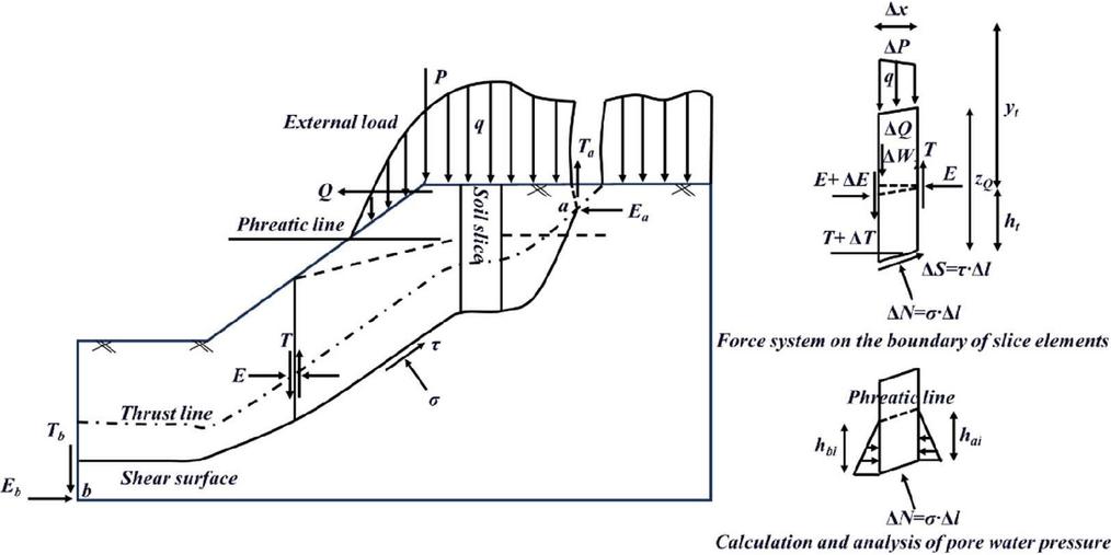
Figure 1 Slope force analysis.
This paper introduces the calculation of the seepage-induced body force of continuous media in the case of two-dimensional seepage. Based on the principle of hydraulics, the seepage-induced body force is proportional to the hydraulic gradient:
| (13) |
When using numerical methods such as finite elements to calculate the stress field, the volumetric force generated by seepage, represented by Equation (13), can be transformed into the external load of the element node for calculation. The seepage-induced body force of the element can be transformed into the equivalent nodal load of the element through the following formula:
| (14) | ||
| (15) |
The stress field influences the seepage field primarily by altering the soil’s permeability coefficient. In porous, equivalent-continuum geotechnical materials, the application of external loads typically induces substantial compressive deformation, resulting in a consolidation process that modifies the internal pore structure [15]. This deformation affects the soil’s porosity, which in turn alters its permeability characteristics. When the soil is modeled as an incompressible porous medium, any variation in pore volume translates directly into volumetric strain, thereby influencing the seepage behavior of the material. Consequently, changes in the stress field lead to adjustments in the void ratio and porosity of the medium. Given that the permeability coefficient is highly sensitive to porosity distribution, variations in porosity inevitably result in corresponding changes in permeability, ultimately modifying the configuration of the seepage field.
The permeability coefficient of soil is closely related to the porosity ratio and is a function of the porosity ratio (or porosity). The larger the porosity (or porosity ratio), the greater the permeability coefficient [16, 17].
| (16) |
The permeability coefficient of normally consolidated cohesive soil can be expressed as:
| (17) |
Assuming that the volumetric strain is all caused by the change in pore volume, the porosity n of the element after being subjected to force is:
| (18) | ||
| (19) |
From the above analysis, the stress field affects the permeability coefficient of the soil by influencing the porosity ratio (rate) of the soil [18] and ultimately affects the entire seepage field. Due to the lack of experiments, this paper adopts the empirical formula of the permeability coefficient varying with porosity proposed by Rivera Bustos et al. [19]:
| (20) |
2.3 Coupled Mechanical Mathematical Model
Building on the preceding analysis, a coupled mathematical model for porous media can be established to describe the interaction between the seepage and stress fields.
2.3.1 Two-dimensional steady-state seepage model that incorporates the influence of the stress field
| (21) |
2.3.2 Stress field mathematical model incorporating the influence of the seepage field
| (22) |
2.3.3 Finite Element Formulation for the Coupled Seepage–stress Field
By integrating the steady-state seepage model influenced by the stress field with the stress field model affected by seepage, a two-way coupled finite element model can be formulated. This coupled system is represented in matrix form as follows:
| (23) |
Equation (23) represents the coupled two-field model describing the behavior of soil under seepage influence. With appropriate boundary and initial conditions specified, the interaction between the seepage and stress fields can be quantitatively characterized.
2.4 Instability Criterion and Failure Judgement
This paper adopts the strength reduction method (SRM) to evaluate slope stability at selected transient time steps during rainfall. Material parameters are reduced as and . The global factor of safety (FoS) is taken as the critical reduction factor at which the system fails to converge or a continuous plastic zone propagates from the slope toe toward the crest. Failure is declared when FoS 1.0, while FoS 1.05 is considered marginally stable for engineering judgement. These criteria are used consistently when interpreting the coupled results reported in Section 3.
The proposed coupled framework targets unsaturated to near-saturated soil slopes (clayey/sandy soils) subjected to rainfall infiltration or moderate reservoir level fluctuation, modeled as an equivalent-continuum under small-strain elastoplasticity with Mohr-Coulomb strength. It is not intended for rock slopes dominated by persistent structural planes, debris flows with intense grain–fluid interactions, or problems requiring fully three-dimensional large deformation.
3 Simulation Analysis of Solid Coupling of Rainfall, Inflow, and Seepage in Slope
3.1 Finite Element Model Establishment
To investigate slope stability under the coupled influence of seepage and stress, as well as to evaluate the impact of various factors on the safety factor, this study simplifies the geometry of a specific reservoir slope and constructs a two-dimensional numerical model for analysis. The slope’s geometric configuration is illustrated in Figure 2. The soil parameters used in the model include cohesion kPa, internal friction angle , elastic modulus MPa, Poisson’s ratio , and bulk unit weight kN/m. The hydraulic conditions are defined with an upstream water level of 16 m, a downstream water level of 10 m, a soil permeability coefficient of m/s, and an initial void ratio of 1. For the slope under dry conditions, plane strain elements (CPE4) are used, while pore fluid-stress coupled elements (CPE4P) are employed to simulate the seepage–stress interaction. Boundary constraints include horizontal displacement fixation at nodes AF and DE on the lateral edges, and full displacement constraints at the model base along EF. Both lateral boundaries are assigned pore pressure boundary conditions that vary linearly with water depth, while the pore pressure along line DC is set to zero. The sloped face BC is designated as a free-draining surface. The finite element mesh, shown in Figure 2, consists of 496 nodes and 450 elements.
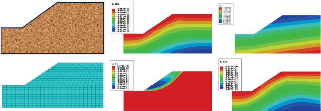
Figure 2 Finite element model.
The model medium is an ideal elastoplastic material and complies with the Mohr-Coulomb strength criterion. The soil-water characteristic curves (SWCCs) for the various rock and soil types were derived by fitting experimental data using built-in functions available in the SEEP/W module, as shown in Figure 3(a). With the saturated hydraulic conductivity and the corresponding SWCCs provided, the unsaturated permeability functions were estimated using the Van Genuchten model. The resulting permeability coefficient curve is presented in Figure 3(b).
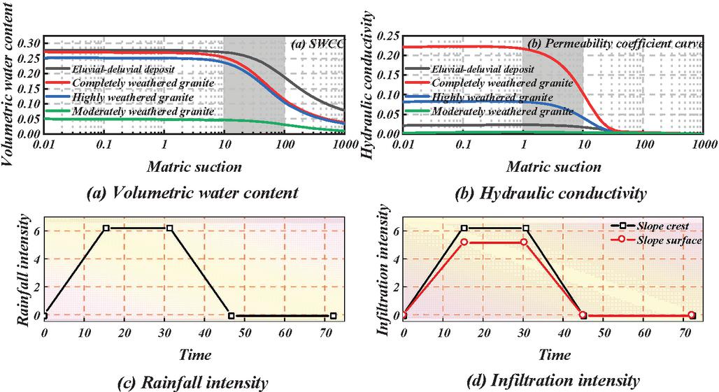
Figure 3 SWCC curve and permeability coefficient.
Using on-site rainfall conditions and regional meteorological data as a reference, this study simulates the evolution of the seepage and stress fields within the slope under a heavy rainfall scenario characterized by a precipitation rate of 150 mm/day. The temporal pattern of rainfall intensity is illustrated in Figures 3(c) and 3(d). Rainfall intensity increases linearly to its peak, remains constant for 15 hours, and then decreases linearly to zero. The total simulation period is 72 hours, during which rainfall occurs for 45 hours, yielding a cumulative precipitation of 187.5 mm. When the rainfall intensity reaches 6.25 mm/h, the infiltration rate at both the slope crest and toe is set to match this value, while the infiltration intensity along the inclined slope surface is assigned as 5.2 mm/h.
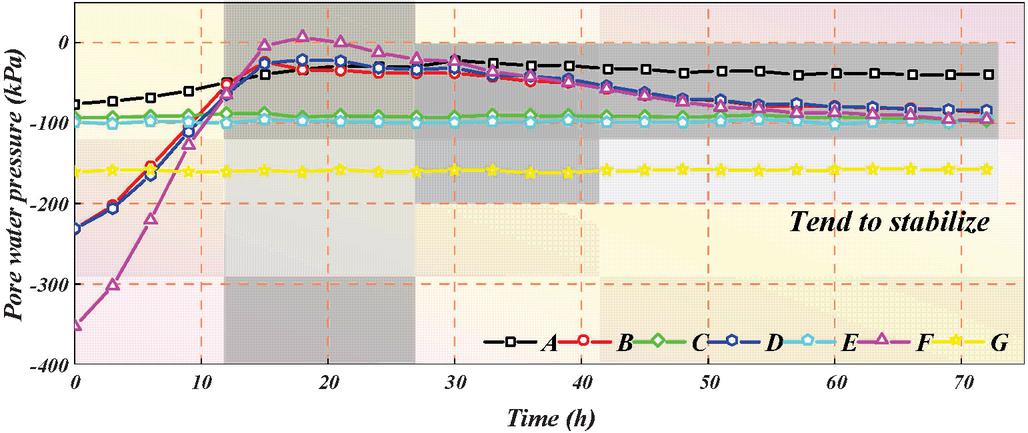
Figure 4 Pore water pressure.
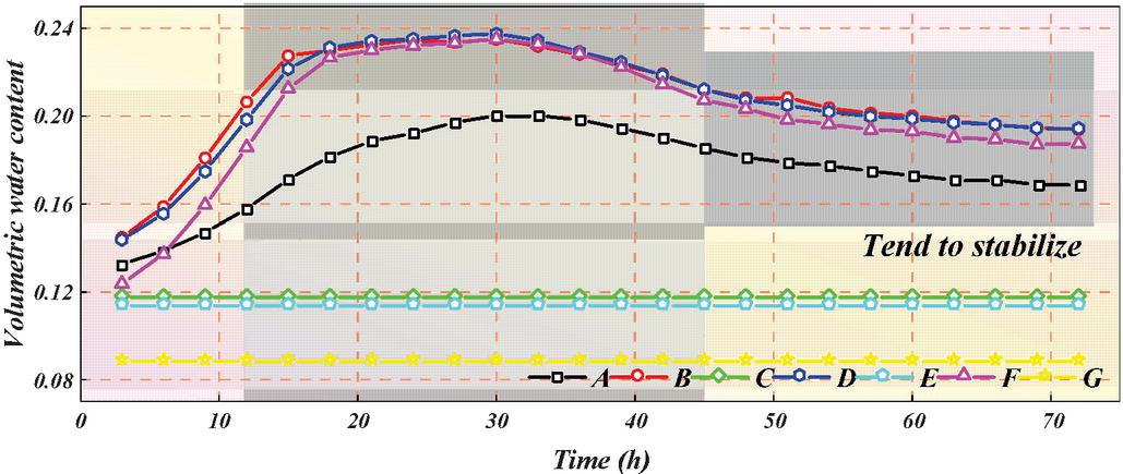
Figure 5 Volume water content.
3.2 Analysis of the Seepage Field and the Stress Field
Figure 4 illustrates the temporal variation of pore water pressure at key monitoring points A through G. During the initial 15 hours, as rainfall intensity increased progressively, the pore pressure in the slope’s surface layer responded rapidly. Notable increases were observed at points A, B, D, and F, with point F exhibiting the most significant rise, approaching saturation. Between 15 and 30 hours, when rainfall intensity remained constant, a decline in pore pressure was recorded at point F, while the pressure curves at points A, B, and D began to converge, and their rates of increase slowed. This behavior suggests that, during this phase, moisture began migrating from the surface layer toward the slope toe. From 30 to 72 hours, rainfall intensity decreased linearly until precipitation ceased entirely. Overall, the pore water pressure showed a downward and decreasing trend with a relatively small reduction. There was still a lag phenomenon that the pore water pressure had not completely dissipated within 72 hours (27 hours after the rain stopped). At monitoring points C, E, and G, located within the interior of the slope, pore water pressure remains essentially unchanged, highlighting a stark contrast with the rapid and pronounced responses observed in the surface soil layer. As shown in Figure 5, the temporal variation of volumetric water content at points A through G closely mirrors the trend of pore water pressure. The surface soil exhibits a clear positive correlation between rainfall intensity and volumetric water content, while the interior of the slope remains largely unaffected by infiltration. In the shallow layers, volumetric water content increases steadily and reaches its peak within 30 hours, followed by a slight decline or rebound between 30 and 72 hours. According to unsaturated soil mechanics, matric suction in unsaturated zones contributes positively to slope stability by enhancing shear strength. However, as rainfall persists, water content within the unsaturated zone rises, leading to a reduction in negative pore pressure, namely a decrease in matric suction. This reduction weakens the contribution of suction to the soil’s shear strength, thereby compromising slope stability. In natural environments, matric suction typically increases during dry periods and diminishes during rainfall events. The associated decline in soil strength during the wet season can ultimately trigger landslide failures.
The seepage field alters pore water pressure distribution, disrupting the original stress equilibrium and resulting in a reduction of effective stress, as illustrated in Figures 6 and 7. During the initial 0–30 hours, as rainfall intensity increases to a steady value, effective stress at monitoring points B, D, and F on the slope declines markedly, with the most significant decrease observed at point F, located near the slope crest. Between 30 and 72 hours, as rainfall intensity gradually diminishes and eventually ceases, a slight recovery in effective stress is noted near the slope surface. According to Fredlund’s shear strength framework for unsaturated soils, a decrease in effective stress directly undermines the shear strength of unsaturated soils, thereby increasing the potential for slope instability.
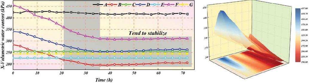
Figure 6 X-axis is effective stress.
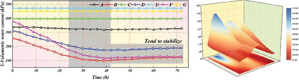
Figure 7 Y-axis is effective stress.
As effective stress decreases, the stress field at the slope surface is altered, inducing deformation that manifests as measurable displacements in the soil elements, as depicted in Figures 8 and 9. Both horizontal and vertical displacements at the monitoring points increase progressively during rainfall, with the most pronounced variations occurring in the shallow soil layers. Among all points, feature point F exhibits the greatest vertical displacement, approximately three times greater than its horizontal counterpart. This deformation is primarily attributed to water absorption by the soil at the slope crest, which causes vertical expansion and upward displacement due to swelling. The horizontal displacement growth rate of feature point B is the fastest, and its vertical displacement is second only to that of point F. This behavior can be attributed to the steepness of the slope’s leading edge and the absence of confinement in the downslope direction, making it susceptible to horizontal displacement and localized soil collapse. At feature point A, only horizontal displacement is observed. Rainfall increases the moisture content and, consequently, the self-weight of the slope soil, thereby enhancing the driving force for sliding. This increased sliding force is transferred downslope, producing a compressive effect at the slope toe and resulting in outward horizontal deformation. Under prolonged rainfall, the slope toe becomes increasingly vulnerable to sliding instability due to the transmitted stress and deformation.
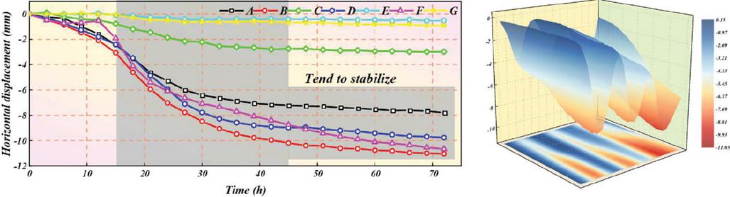
Figure 8 Horizontal displacement.
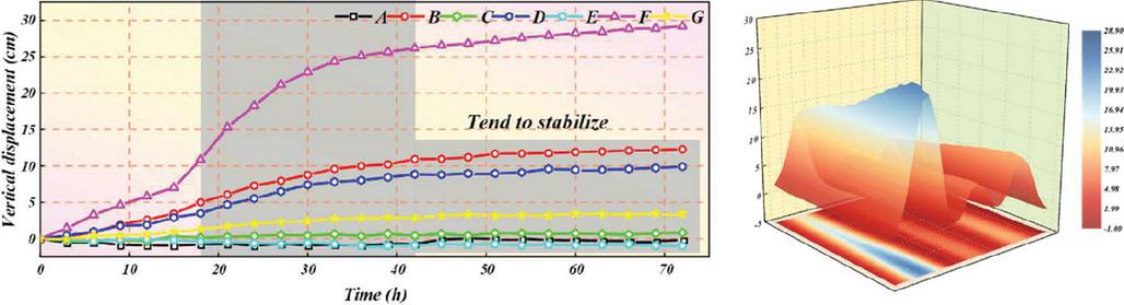
Figure 9 Vertical displacement.
This study also has some limitations: (1) The analysis adopts a small-strain elastoplastic formulation; localized large deformation and strain-softening band formation are approximated but not fully resolved. (2) Hydraulic conductivity is represented by an equivalent continuum with scalar or weakly anisotropic ; spatial heterogeneity and time-dependent clogging are simplified. (3) Parameter identification (e.g., SWCC and ) relies on site-specific calibration; uncertainty propagation to FoS under nonstationary rainfall is not addressed and will be pursued in future work.
4 Prevention and Control Measures for Landslide Disasters
4.1 Slope Drainage and Prevention Facilities
The drainage facilities on the slope surface mainly include water interception ditches, plunge channels, rapid flow channels, side ditches, drainage ditches, and other setting forms.
(1) This drainage measure is designed to capture surface runoff flowing from higher elevations, thereby preventing erosion and scouring at the slope base. When installed along the outer edge of a cut slope’s crest, interception ditches can significantly mitigate the damaging effects of surface water runoff on slope stability. According to the location and function set, the water interception ditches can be divided into platform water interception ditches and top of the slope water interception ditches. The platform water interception ditch is usually located at the platform. The water interception ditch at the top of the slope is set not far from the top of the slope (about 5 meters), collecting water from above the top of the slope to prevent the slope surface from being eroded [20]. The water interception ditch should be set up flexibly according to the actual situation of the slope and where it is located. In areas with little rainfall, good vegetation, and good slope mechanical parameters, water interception ditches need not be set up. In areas with abundant rainfall, poor vegetation conditions, soft slopes, and those greatly affected by erosion, many water interception ditches can be set up. Meanwhile, the locations where water interception ditches are set up should be reasonably laid out in combination with the terrain and geographical conditions [21].
(2) A drop facility causes the water flow from the upstream channel to fall into the downstream channel. It is mostly used in areas with a large vertical drop and is connected to the overflow weir as a water discharge and drainage structure on the channel. The cross-section of the falling trough is rectangular. It is stipulated that the depth direction of the cross-sectional dimensions shall not be less than 0.2 m, and the width shall not be less than 0.25 m.
(3) A rapids channel refers to an artificial channel with a slope greater than the critical slope. It can guide the water flow and slow down the water flow rate in cases of large drops, short horizontal distance, and steep slopes. Its cross-section is generally rectangular, groove depth is usually greater than 0.2 m, and width of the groove bottom is greater than 0.25 m. In engineering, it can be set up alone on the side of the slope or used in combination with other drainage measures to fully exert its role in diverting water, ease the flow rate, and eventually discharge the water to the bottom of the slope or the drainage ditch. In terms of specific functions, the jet channel is composed of three parts, as shown in Table 2.
Table 2 Composition and function of the jet channel
| Serial Number | Location | Name | Function |
| 1 | Water inlet | Diversion | Change the direction of the water flow |
| 2 | Slot body | Rapids | Reduce the flow rate |
| 3 | Outlet | Beam current | Prevent overflow at the water outlet |
The presence of water within the slope exerts a dual influence on slope stability. Infiltration increases the self-weight of the slope, and the movement of water through the soil can generate dynamic forces that further compromise structural integrity [22]. Moreover, water acts as a lubricant, weakening the bonding between soil or rock particles. The interaction between water and soil matrix reduces matric suction, particularly along weak surfaces formed in saturated zones, thereby diminishing shear strength and adversely affecting slope stability. If other adverse factors such as earthquakes and slope excavation induce it, the slope will immediately become unstable and fail.
In cases where the groundwater level in the edge slope body is relatively low, and the water content does not affect the safety of the slope, slope body drainage may not be set up. This is because underground drainage facilities are generally expensive and have high maintenance costs in the later stage. Therefore, surface drainage is the main method for such slopes [23]. For slopes with poor rock and soil properties, underground drainage facilities must be set up otherwise the groundwater level poses a hidden danger to the stability of the slope.
4.2 Drainage Design Calculation
Heavy rainfall-induced landslides primarily result from surface water accumulation and increased subsurface moisture within the slope. As rainfall infiltrates the soil, the water content rises, leading to notable changes in the soil’s physical and mechanical behavior. Specifically, the negative pore water pressure (matric suction) within the unsaturated zone decreases, approaching zero. This reduction diminishes the soil’s shear strength, while the added moisture simultaneously increases the slope’s self-weight, both of which contribute to slope instability. Eventually, this leads to greater deformation of the slope and causes landslides [24]. Drainage can eliminate the water pressure of groundwater and dry the soil of the landslide mass, thereby reducing the specific gravity of the mass and improving the shear strength index, reducing soil deformation and increasing slope stability, reducing the methods of landslide engineering treatment and saving engineering investment.
When rainfall intensity exceeds the saturated permeability of the slope material, surface water begins to accumulate, resulting in the formation of overland flow. The convergence flow rate of surface water discharged by using drainage ditches and interception ditches is:
| (24) |
where represents the flow rate of the designed surface water sink. The cross-sectional shape of the landslide drainage ditch can be rectangular or trapezoidal. The flow rate of the drainage ditch is calculated by:
| (25) |
According to Equations (24) and (25), the cross-sectional areas of the landslide interception ditch and drainage ditch can be obtained as follows:
| (26) |
The landslide drainage ditch is set on the stable slope surface 5 meters away from the sliding surface on the outside of the edge of the landslide body. The planar layout is mostly circular according to the terrain. Drainage holes are set on the water-facing side of the slope water interception ditch, with the size of the drainage holes ranging from 100 100 mm to 300 300 mm.
The underground drainage of landslides is based on the principles of dewatering and diversion. The main engineering measures include drainage tunnels, blind drainage ditches, and drainage holes. Generally, drainage tunnels are divided into two types: transverse and longitudinal. Transverse drainage tunnels are set below the sliding surface at the rear edge of the landslide body and are perpendicular to the direction of groundwater flow [25]. Longitudinal drainage tunnels are set within the landslide body, with branch drainage tunnels and inclined drainage holes connected on both sides that are perpendicular to the direction of groundwater flow. When there is a wetland with accumulated water on the surface of the landslide body, the upper end of the drainage ditch should be made into a blind ditch extending into the wetland. The blind drainage ditches for landslides should be filled with block stones and crushed stones without mud, and filter layers should be built on both sides and the top [26, 27].
When the rainfall infiltration slope is in the limit state:
| (27) | |
| (28) |
The water inflow volume for draining saturated soil water by using landslide drainage tunnels or blind drainage ditches is:
| (29) |
4.3 Slope Stability Monitoring After Treatment
Based on the completion plan of the monitoring project provided by the construction unit and some monitoring work data during the construction stage and based on the mechanical calculation method of slope stability coupling of seepage field and stress field proposed in this paper, the effect monitoring work of the slope drainage disaster reduction and treatment project for one hydrological year was carried out. In January 2023, a monitoring network was set up on site, and the control measurement and adjustment processing of the monitoring area were completed on 17 January 2024. By the requirements of the monitoring implementation plan for this project, the monitoring of this project adopts a combined monitoring method of professional monitoring of earth deformation, ground fissure monitoring, and macroscopic geological inspection and patrol.
The professional monitoring system for earth deformation consists of monitoring reference points, working base points, and monitoring points. Before implementing the first phase of effect monitoring, a control network was laid out for the entire project area, and control measurements were carried out using GPS. After adjustment processing and inspection, the control measurement data were finally formed, as shown in Figures 10 and 11.
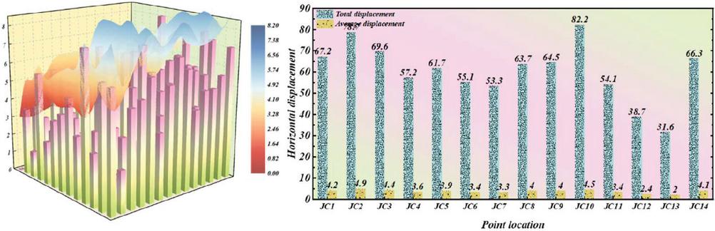
Figure 10 Time-variation curves of horizontal displacement at monitoring points.
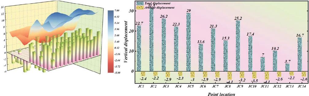
Figure 11 Time-variation curves of vertical displacement at monitoring points.
According to the displacement statistics from this monitoring project, the annual average horizontal displacements recorded at 14 monitoring points are as follows: 4.2 mm, 4.9 mm, 4.4 mm, 3.6 mm, 3.9 mm, 3.4 mm, 4.0 mm, 4.5 mm, 3.4 mm, 2.4 mm, 2.0 mm, 4.1 mm. The corresponding vertical displacements are: 2.4 mm, 2.2 mm, 2.9 mm, 2.3 mm, 3.0 mm, 2.9 mm, 2.9 mm, 4.1 mm, 3.2 mm, 3.5 mm, 4.1 mm, 2.6 mm, 2.1 mm, 2.6 mm. These monitoring results indicate that both the horizontal and vertical displacement values remain below twice the median error of the respective monitoring points. Furthermore, no progressive increase in displacement over time is observed, suggesting overall slope stability throughout the monitoring period.
Based on the analysis of the professional monitoring data results of the previous hydrological monitoring year, in the project area after drainage disaster reduction and treatment, there was no trend of displacement, deformation, or increasing deformation at the monitoring points. The deformation change was within the error range, and the displacement and deformation were not obvious. The macroscopic geological inspection results of the previous hydrological monitoring year showed that no obvious signs of macroscopic deformation were found in the monitoring area. This indicates that the slope stability mechanical design and calculation method based on seepage–stress coupling proposed in this paper has obvious advantages and good prevention and control effects.
The failure mechanism of a landslide is as follows: (i) Siltation and bio-clogging at inlets and perforations reduce effective area and raise hydraulic head, leading to overflow along unintended paths. (ii) Filter malfunction (improper gradation/geotextile choice) triggers fines migration and internal erosion. (iii) Scour and lining damage in drops/rapid channels under peak discharges causes structural cracking and leakage. (iv) Extreme-rainfall overtopping exceeds design return period, inducing bypass flow and erosion at shoulders.
The measures taken to address the failure mechanism of a landslide are as follows: (a) Redundant staged drainage (crest interception rapid channel toe ditch) to avoid single-point failure; (b) Maintainable inlets with debris screens, accessible clean-outs, and minimum inspection frequency before/after rainy seasons; (c) Graded filter geotextile meeting anti-piping criteria; (d) Energy dissipation (stilling basins/roughness elements) and anti-scour lining at outlets; (e) Capacity check with safety margins for design storms; (f) Monitoring via simple head/flow markers enabling quick blockage detection.
5 Conclusion
This paper has achieved remarkable innovative results in the field of mechanical calculation of landslide stability and optimization of drainage disaster reduction. By systematically developing a finite element model that couples the seepage and stress fields, this study presents a comprehensive analysis of the dynamic evolution of seepage, stress, and displacement within a slope during rainfall infiltration. For the first time, the underlying mechanisms by which seepage–stress interactions affect slope stability are quantitatively revealed.
1. Simulation results under extreme rainfall conditions, defined by a rainfall intensity of 6.25 mm/h and a cumulative total of 187.5 mm, demonstrate a rapid increase in pore water pressure within the slope’s surface soil during the first 15 hours, with a peak rise exceeding 80%. Concurrently, effective stress decreases by more than 30%, triggering substantial deformations in both horizontal and vertical directions. The maximum vertical displacement reaches 12 cm, occurring at the slope crest, while the highest rate of horizontal displacement growth, measured at 0.5 mm/h, is observed near the steep leading edge of the slope. These quantitative findings not only validate the reliability of the coupled model but also offer critical scientific evidence to support early warning systems and landslide disaster mitigation strategies.
2. The design method of slope flood control and drainage facilities and the calculation method of drainage design proposed in this paper have been verified through long-term monitoring of specific engineering cases, which has proved their significant effects in practical applications. Monitoring data show that after the drainage disaster reduction treatment of the slope, the annual average horizontal displacement and vertical displacement of the monitoring points have been effectively controlled within a very small range (horizontal displacement 4.5 mm, vertical displacement 4.1 mm), and there is no trend of increasing deformation. Compared with before the treatment, the displacement has decreased by more than 60%, significantly improving the stability of the slope and effectively reducing the risk of landslide disasters.
3. The findings of this study not only enhance the theoretical framework for landslide stability analysis but also offer practical, implementable strategies for landslide disaster prevention and mitigation. These contributions hold significant scientific importance and demonstrate broad applicability in geotechnical engineering practice. Looking ahead, as research continues to advance and related technologies evolve, the theoretical models and methodologies developed herein are expected to play an increasingly pivotal role in landslide early warning systems and risk management strategies.
We believe this paper will extend the framework to three-dimensional, large-deformation hydromechanical coupling with spatially variable parameters and uncertainty quantification and explicitly couple drainage facility ageing and clogging into to close the loop between design, deterioration and risk. The demonstrated 60% reduction in post-treatment displacement provides a quantitative target for performance-based drainage retrofits in similar slopes.
Funding
This study is funded by Project Research on Risk Control of Soil Cave Mud Outburst and Collapse Disasters in Dongshan Water Conveyance Project (sz-2020-29).
References
[1] Z Ma, C Zhu, X Yao, F Dang. (2021). Slope stability analysis under complex stress state with saturated and unsaturated seepage flow. Geofluids 2021(1), 6637098.
[2] D Qu, Y Luo, X Li, G Zhang, K Xu. (2020). Study on the stability of rock slope under the coupling of stress field, seepage field, temperature field, and chemical field. Arabian Journal for Science and Engineering 45(5), 8315–8329.
[3] S Wang, T Yang, Z Zhang, Z Sun. (2021). Unsaturated seepage–stress–damage coupling and dynamic analysis of stability on discrete fractured rock slope. Environmental Earth Sciences 80(21), 1–23.
[4] L Wu, B He, J Peng. (2024). Analysis of rainfall-caused seepage into underlying bedrock slope based on seepage deformation coupling. International Journal of Geomechanics 24(5), 04024076.
[5] J Xu, K Ueda, R Uzuoka. (2022). Numerical modeling of seepage and deformation of unsaturated slope subjected to post-earthquake rainfall. Computers and Geotechnics 148(3), 104791.
[6] S Yu, X Ren, J Zhang, H Wang, J Wang, W Zhu. (2020). Seepage, deformation, and stability analysis of sandy and clay slopes with different permeability anisotropy characteristics affected by reservoir water level fluctuations. Water 12(1), 201.
[7] L He, D Kong, D Wu, Y Shang, G Song. (2025). Study on the failure mechanism of high and steep slope considering the seepage pressure of reservoir water level. Physics of Fluids 37(4), 15–22.
[8] C Zhou, Z Shen, L Xu, Y Sun, W Zhang, H Zhang, J Peng. (2023). Global sensitivity analysis method for embankment dam slope stability considering seepage–stress coupling under changing reservoir water levels. Mathematics 11(13), 2836.
[9] M Xu, A Jiang, X Yang, T Jiang. (2021). Elastoplastic-damage-seepage coupling model and numerical algorithm for rock slope stability evaluation. International Journal of Damage Mechanics 30(9), 1450–1472.
[10] Z Hu, Z X Yang, N Guo, Y D Zhang. (2022). Multiscale modeling of seepage-induced suffusion and slope failure using a coupled FEM–DEM approach. Computer Methods in Applied Mechanics and Engineering 398(24), 115177.
[11] S Xu, A M Zsáki. (2021). Maximum safe freight train speed on railway embankments under rapid drawdown conditions based on coupled stress-seepage slope stability analysis. Transportation Geotechnics 27(9), 100486.
[12] A Z Belew, D Y Tenagashaw, W T Ayele, T G Andualem. (2022). Coupled analysis of seepage and slope stability: a case study of Ribb embankment dam, Ethiopia. Water Conservation Science and Engineering 7(3), 293–314.
[13] H Liu, W Shi, T Yang. (2020). Numerical modeling on anisotropy of seepage and stress fields of stratified rock slope. Mathematical Problems in Engineering 2020(1), 4956025.
[14] Y Sun, Z Li, K Yang, G Wang, R Hu. (2023). Analysis of the influence of water level change on the seepage field and stability of a slope based on a numerical simulation method. Water 15(2), 216.
[15] S Zhao, Z Shi, M Peng, Y Bao. (2020). Stability analysis of expansive soil slope considering seepage softening and moistening expansion deformation. Water 12(6), 1678.
[16] A N El-Hazek, N B Abdel-Mageed, M H Hadid. (2020). Numerical and experimental modelling of slope stability and seepage water of earthfill dam. Journal of Water and Land Development 6(18), 55–64.
[17] Z Dai, S Chen, J Li. (2020). Physical model test of seepage and deformation characteristics of shallow expansive soil slope. Bulletin of Engineering Geology and the Environment 79(5), 4063–4078.
[18] C Wang, B Hawlader, D Perret, K Soga, J Chen. (2021). Modeling of initial stresses and seepage for large deformation finite-element simulation of sensitive clay landslides. Journal of Geotechnical and Geoenvironmental Engineering 147(11), 04021111.
[19] A Rivera Bustos, E Ledoux. (1990). Modèle hydrogéologique quasi-tridimensionnel non-linéaire pour simuler la subsidence dans les systèmes aquifères multicouches-Cas de Mexico. Doctorat en hydrologie et hydrogéologie quantitatives de l’ENS Mines de Paris.
[20] G Li, Y Wang, D Wang, L Wang, S Zhang, C Li, R Teng. (2023). The creep behavior of rock shear seepage under different seepage-water pressures. Mechanics of Time-Dependent Materials 27(2), 351–365.
[21] W G Louhenapessy, B Lareno. (2022). Analyzing the effect of water seepage and scour on slope stability using finite element method. Jurnal Teknik Sipil 18(2), 216–229.
[22] L Yu, X Zheng, Z Liu, C Zhou, L Zhang. (2022). Multiscale modelling of the seepage-induced failure of a soft rock slope. Acta Geotechnica 17(10), 4717–4738.
[23] S Huang, Y Lyu, H Sha, L Xiu. (2021). Seismic performance assessment of unsaturated soil slope in different groundwater levels. Landslides 18(8), 2813–2833.
[24] Y Feng, F Yan, L Wu, G. Lu, T. Liu. (2023). Numerical analyses of slope stability considering grading and seepage prevention. Water 15(9), 1745.
[25] Y Tan, J Cao, W Xiang, W Xu, J Tian, Y Gou. (2023). Slope stability analysis of saturated–unsaturated based on the GEO-studio: a case study of Xinchang slope in Lanping County, Yunnan Province, China. Environmental Earth Sciences 82(13), 322.
[26] M B Hailu. (2021). Modeling assessment of seepage and slope stability of dam under static and dynamic conditions of Grindeho Dam in Ethiopia. Modeling Earth Systems and Environment 7(4), 2231–2239.
[27] D Yu, Q Huang, X Kang, Y Liu, X Chen, Q Xie, Z Guo. (2023). The unsaturated seepage process and mechanism of internal interfaces in loess-filled slopes during intermittent rainfall. Journal of Hydrology 619(8), 129317.
Biography

Danqing Zhang (born December 1967), female, Han ethnicity, native of Yuncheng, Shanxi Province, China, holds a postgraduate degree from Taiyuan University of Technology and is currently an Associate Professor. Research Directions: Hydrogeology and Engineering Geology; Geotechnical Engineering.
European Journal of Computational Mechanics, Vol. 34_2, 169–194.
doi: 10.13052/ejcm2642-2085.3424
© 2025 River Publishers