Study on the Structure and Seismic Performance of Irregular Structure Damper Optimized by Computer Algorithm
Xiaohui Wu*, Yanfeng Wang and Weixian Che
Power Grid Planning Research Center of Guangdong Power Grid Co. Ltd., Guangzhou 510220, China
E-mail: 13570133334@139.com
*Corresponding Author
Received 16 June 2025; Accepted 12 August 2025
Abstract
This study addresses the seismic performance improvement of complex and irregular indoor substations in high-intensity areas by integrating computer algorithm optimization with new damper technology. With the rapid development of urban construction, unconventional buildings with complex shapes are becoming more common. Indoor substations exhibit significant planar and vertical irregularities due to equipment installation needs. The spatial misalignment between the mass center and stiffness center exacerbates the planar-torsional coupling effect under seismic loads, making traditional seismic design methods inadequate for high-intensity area seismic codes. This research aims to address the issues of insufficient parameter allocation accuracy and hardware performance limitations in existing energy dissipation and vibration reduction technologies when applied to irregular structures through innovative algorithm optimization and damper design. Methodologically, an improved Kasai method is proposed to construct a dynamic allocation strategy for multi-degree-of-freedom system damping parameters. A single-degree-of-freedom equivalent subsystem and multi-degree-of-freedom parameter coupling optimization model are established. A damper configuration algorithm considering the non-uniform distribution of inter-story drift ratios is developed. By introducing a dynamic allocation coefficient, the critical layer non-uniform configuration of damping parameters is achieved. An optimization model for stiffness-damping coupling regulators is established to ensure that the convergence condition of the algorithm is met with Rd–Rd5%. The 3D finite element model is constructed using SAUSAGE software, and time-history analysis is conducted using five natural waves and two artificial waves for validation. Additionally, a new viscous damper with improved damping holes is designed, and frequency-dependent, low-speed friction, and fatigue performance tests are conducted using a 3530 kN electro-hydraulic servo system. The results show that the improved algorithm reduces the number of dampers by 15% compared to traditional designs. Under moderate seismic conditions, the maximum vibration damping efficiency in the X/Y-directions reaches 37.18% and 21.09%, respectively, with inter-story drift ratio precisely controlled within the 1/400 limit. The new Type B damper shows an 8% reduction in measurement error compared to the traditional Type A damper under a 9.425 mm/s condition. After 30 fatigue cycles, the damping force decay rate is only 7.8%, and the energy dissipation efficiency increases by 23%. The study confirms that the improved Kasai method effectively overcomes the precision issues in the parameter allocation of traditional equivalent linearization models for multi-degree-of-freedom systems. When combined with the new damper, it can reduce the flat torsion coupling vibration effect by more than 40%. This achievement breaks through the design bottleneck of seismic resistance for complex structures in high-intensity areas. By innovating in both algorithm and hardware, it establishes a new paradigm for intelligent vibration damping system design, providing a solution that is both cost-effective and reliable for critical infrastructure. It also promotes the transition of energy dissipation and vibration damping technology towards model-driven methods, offering significant engineering value and social benefits in enhancing the earthquake resilience of urban infrastructure.
Keywords: Substation, irregular structure, Kasai method, seismic control, new viscous damper.
1 Introduction
The rapid advancement of urban construction and the diversification of functional needs have led to the emergence of a large number of complex unconventional buildings. This is also true for indoor substations, which are special industrial structures. To meet the unique installation requirements of transformers, reactors, and other equipment, their architectural forms often exhibit significant irregularities in both plan and elevation [1]. While achieving multifunctional integration, these buildings face severe design challenges in their structural systems. The quality center and stiffness center of unconventional building structures typically have spatial discrepancies. Under seismic excitation, the inertial forces generated by the quality center will act on the stiffness center, creating a torque effect that triggers structural torsional-vibration coupling, leading to noticeable torsional deformation. Seismic damage survey data show that the irregularity of building shapes significantly weakens their seismic performance, potentially causing structural failure or continuous collapse with serious consequences [2–4].
Wang [5] conducted research on large-span and irregular planar building systems, comparing the applicability of the Ritz method and the eigenvector method. The results show that the former has a greater advantage in obtaining higher-order modes, especially for dynamic analysis of irregular structures. Oz et al. [6] investigated the impact of irregular torsional behavior in L-shaped reinforced concrete (RC) structures under soil-structure interaction (SSI) on seismic response, proposing vibration reduction measures using tuned mass dampers (TMD). However, they failed to thoroughly explore the adaptability of TMD parameter optimization to complex torsional effects and neglected the spectral characteristics differences in actual seismic motions. Yang et al. [7] developed a collaborative control strategy for multi-viscoelastic dampers (MR dampers) based on ant colony optimization algorithms to suppress coupled vibrations in spatially irregular structures. This control strategy was only validated on specific structural models without practical engineering verification and did not account for long-term performance degradation of dampers. Babar and Patil [8] compared seismic performance of various dampers (viscous dampers, friction dampers) and base isolation systems in multi-story irregular steel structures. However, the study remained confined to single-building models without extending to structures of varying heights or materials and failed to quantify economic feasibility and construction viability. Kontoni and Farghaly [9] analyzed vertical/horizontal irregular high-rise steel structures with SSI effects using TMD for seismic response suppression. However, TMD parameter optimization did not consider multidimensional structural coupling effects, and the simplified SSI model might underestimate real-world site impacts. Abolghasemi et al. [10] investigated seismic performance of strongback systems in structures with different damper configurations and stiffness abrupt changes. However, the optimal position selection criteria for dampers remain undefined, and their applicability to concrete structures lacks validation. Apaer et al. [11] optimized TMD parameters using the Jaya algorithm for seismic design of torsionally irregular structures. However, the algorithm failed to account for practical constraints (such as spatial limitations and damper installation costs), only verifying linear models without addressing nonlinear seismic responses. Saurav et al. [12] compared linear dynamic responses of high-rise irregular structures with/without lateral force-resisting systems (LFRS) and friction dampers. Yet the linear analysis did not incorporate structural nonlinear behavior, and damper performance depended on preset slip forces without discussing adaptive control. Ali and Abdolhossein [13] enhanced seismic reliability and control effectiveness of irregular structures using magnetorheological dampers (MR dampers). However, the control algorithm lacked adaptability under multiple earthquake intensity levels and failed to analyze damper failure impacts on system reliability. Khan et al. [14] investigated vibration control effects of single/multi TMDs on irregular structures, comparing their seismic reduction efficiency. Yet they neglected spatial occupancy issues under large TMD displacement requirements and insufficiently analyzed potential interference mechanisms between multiple TMDs. Ghaderi et al. [15] investigated the optimal arrangement of inerter-connected tuned liquid column dampers (IC-TLCDs) to improve the seismic performance of building structures with vertical mass irregularities. Optimization algorithms (such as genetic algorithms or particle swarm optimization) are used to determine the optimal position and parameters of IC-TLCDs to reduce the dynamic response of structures under seismic action. Through numerical simulation and comparative analysis, the results show that the reasonable arrangement of IC-TLCDs can significantly reduce the displacement and acceleration response of the structure and improve the seismic ability. However, the verification of practical applications is insufficient: the research is mainly based on numerical simulations, and there is a lack of actual structure or shaker test verification, which may affect the universality of the conclusions.
Literature analysis shows that current energy-saving vibration reduction technologies have achieved significant vibration control effects in conventional buildings. However, existing research has paid insufficient attention to indoor substation structural systems with pronounced irregular plan and elevation features. Such structures located in high-intensity zones (8 degrees) often fail to meet current seismic code requirements due to their complex deformation characteristics. Conducting seismic optimization design for irregular substation structures and developing new dampers holds significant engineering value, effectively enhancing the seismic safety reserve of special industrial buildings.
This study focuses on enhancing the seismic performance of complex and irregular indoor substations in high-intensity areas. It integrates computer algorithm optimization with new damper technology to conduct systematic research. An improved Kasai method is proposed, establishing a dynamic allocation strategy for multi-degree-of-freedom system damping parameters. A coupling optimization model for single-degree-of-freedom equivalent subsystems and multi-degree-of-freedom parameters is developed. A damper configuration algorithm considering non-uniform inter-story drift ratios is also developed. The 3D finite element model is constructed using SAUSAGE software, and time-history analysis is performed using five natural waves and two artificial waves for validation. Additionally, a new viscous damper with improved damping holes is designed, and frequency-dependent, low-speed friction, and fatigue performance tests are conducted using a 3530 kN electro-hydraulic servo system.
This study innovatively designed a novel viscous damper with optimized damping orifice configuration. By refining the orifice geometry, the energy efficiency was enhanced by 23%. Under 9.425 mm/s loading conditions, measurement errors were reduced by 8% compared to conventional models, while the damping force attenuation rate remained at only 7.8% after 30 fatigue cycles. Through dual innovations in algorithms and hardware, the maximum vibration damping efficiency reached 37.18% in X-axis and 21.09% in Y-axis directions. The interlayer displacement ratio was precisely controlled within the 1/400 limit, with damper usage reduced by 15%, computational efficiency increased by 80%, and planar-torsional coupling effects effectively mitigated by over 40%. This breakthrough addresses seismic design challenges in high-intensity zones for complex structures.
2 Damping Parameter Optimization Theory Based on Computer Algorithm
2.1 Improved Kasai Method
The conventional Kasai method is an energy dissipation and seismic reduction design method based on the principle of equivalent linearization. The main idea of this method is to simplify the main structure into an equivalent single-degree-of-freedom structural system through the principle of fundamental frequency equivalence. The target displacement reduction rate is determined based on the maximum drift ratio of the equivalent single-degree-of-freedom structural system and the maximum drift ratio after structural seismic reduction. Then, based on the performance curve of the seismic reduction system, the equivalent single-degree-of-freedom structural system satisfies the target displacement reduction rate and the stiffness ratio with the main structure. Finally, damping parameters are allocated to the multi-degree-of-freedom structural system.
Generally, seismic control technology changes the dynamic performance of a structure by utilizing the additional stiffness of dampers to shorten the system period and the viscous characteristics to absorb energy and increase damping. By increasing the stiffness of the structure, the period of the structure can be changed from the initial period to the equivalent period . The improvement of viscosity performance can be represented by an increase in damping ratio from the initial damping ratio to the equivalent damping ratio . For a single-degree-of-freedom structural system, the displacement response spectrum , pseudo velocity response spectrum , and pseudo acceleration response spectrum have the following relationships:
| (1) |
In structural design, the pseudo velocity response spectrum of structures with moderate or above natural vibration periods are often assumed to be constant. As the period of the damping structure shortens, the displacement decreases and the acceleration increases (effect (1)). Then, as the damping increases, the displacement, velocity, and acceleration all decrease (effect (2)), ultimately leading to a decrease in displacement and acceleration. Of course, the proportion of effects (1) and (2) varies depending on the degree of change in the natural vibration period and damping ratio. If the equivalent period and equivalent damping ratio can be calculated, the magnitude of the reaction reduction effect can be estimated based on the response spectrum. Based on the above effects (1) and (2), the reduction rate of displacement () and pseudo acceleration response () can be expressed as follows:
| (2) | ||
| (3) |
In Equations (2) and (3), the fraction of the second term and the fraction of the third term on the right represent the effect (1) caused by the reduction of the period from to , which can be obtained from Equation (1). The first item on the right represents the effect (2) produced by increasing the damping ratio from to . For the short period indoor substation in this study, according to the proportional relationship between the period and the in Equation (1), it can be obtained that:
| (4) |
In Equations (2) to (4), the damping effect coefficient is used to predict the decrease rate of the response spectrum value when the damping ratio increases from the initial damping ratio to the equivalent damping ratio . The Kasai method derived the following formula based on statistical analysis of 31 actual seismic waves:
| (5) |
The damping coefficient in Equation (5) was established through statistical analysis of 31 actual seismic waves, with the derivation process as follows. First, based on stochastic vibration theory, we formulated the attenuation relationship between damping ratio and spectral acceleration. Second, empirical correction coefficients were obtained through nonlinear regression analysis. This empirical formula shows an error of less than 8% when falls within the range [0.05, 0.4], compared to the Newmark-Hall spectrum.
For viscous dampers with a damping index of , the maximum dynamic response of single-degree-of-freedom structural system can be obtained separately for frictional dampers () and linear viscous dampers (), and then the response of the system with a damping index of can be obtained using interpolation.
When, the equivalent period ratio and equivalent damping ratio can be calculated using:
| (6) |
When , the equivalent period ratio and equivalent damping ratio can be calculated using:
| (7) |
where is the stiffness of the main structure and is the loss stiffness of the damper, in which the loss stiffness is defined as the force at zero deformation. and are the storage stiffness and the loss stiffness of the additional system, which is the system composed of dampers and components connecting dampers to the main structure. The storage stiffness is defined by the force at maximum deformation divided by the maximum displacement. The loss stiffness of the damper, the storage stiffness , and the loss stiffness of the additional system can be expressed by:
| (8) |
where is the damping coefficient of viscous damper and is the maximum displacement of viscous damper.
From the above formulas, it can be seen that the equivalent period and the equivalent damping ratio are mainly determined by various stiffness ratios , , and . Obviously, if the equivalent support stiffness ratio and the additional system damage stiffness ratio is given, the equivalent period ratio and equivalent damping ratio can be calculated when and . Correspondingly, the damping effect coefficient can then be calculated based on Equation (5). Therefore, the reduction rate of displacement () and acceleration response () can be obtained, namely and for and for .
If is within the range of 0 to 1, the reduction rate and can be deduced based on the interpolation method:
| (9) |
It can be seen that the reduction rate and is defined by different parameters of , , and . If these parameters are first determined, the relationship curve, also named as performance curve of single-degree-of-freedom structural system with viscous damper, between and can be obtained. For example, given a structural damping ratio of 0.05, a damping index of 0.3, and , 0.2, 0.3, 0.5, 1, 2, 3, 5, 10, respectively, , 0.1, 0.2, 0.3, 0.5, 1, 2, 5, 10. The performance curve of the damping structure with viscous dampers can be obtained based on the above parameters, as shown in Figure 1.
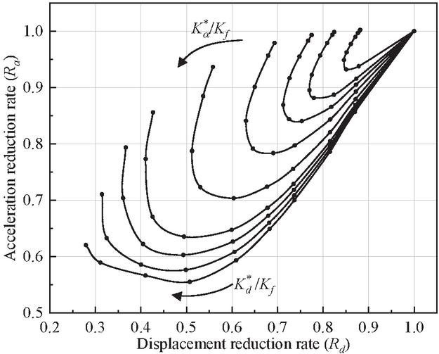
Figure 1 Performance curve of damping structural system with viscous damper.
The traditional Kasai method has several theoretical limitations in the application of energy dissipation and seismic vibration reduction design. First, its single-degree-of-freedom simplified model based on the principle of equivalent linearization (as shown in Equations (6) and (7)) struggles to accurately represent the complex dynamic coupling effects of multi-degree-of-freedom systems, especially in irregular structures with significant planar-torsional coupling characteristics, where the applicability of modal superposition principles is significantly reduced. Second, this method assumes that the pseudo-speed response spectrum remains constant in the medium and higher periods (as described in Equation (1)). However, for short-period structures (such as indoor substations described in Equation (4)), the nonlinear relationship between period and will lead to an interaction bias between effect (1) (period shortening) and effect (2) (damping enhancement), resulting in a decrease in the prediction accuracy of displacement reduction rate and acceleration response in Equations (2) and (3). Furthermore, the interpolation method used to handle the transition state of nonlinear damping index (as shown in Equation (9)) introduces model discretization errors, particularly when the damper exhibits strong nonlinear characteristics (in the range ), making it difficult to fully characterize the dynamic coupling relationship between energy storage stiffness and loss stiffness defined in Equation (8) through linear interpolation. Additionally, the statistical regression formula (Equation (5)) relied upon by this method is based on finite earthquake wave samples, which may produce significant systematic biases when extrapolated to non-stationary seismic input or extreme excitation conditions, limiting the engineering applicability of performance curves (Figure 2). These theoretical deficiencies collectively constrain the accuracy of seismic optimization design for complex irregular structures in high-intensity zones.
In this study, the drift ratio of the damping structural system is proposed as the allocation index for the total damping parameter, which can ensure that different floors have different requirements for the seismic requirement. Firstly, given the seismic design objective of the maximum drift ratio of the multi-degree-of-freedom structural system with viscous damper, the target value of displacement reduction rate can be calculated:
| (10) |
where is the maximum drift ratio of the multi-degree-of-freedom structural system without control, which can be obtained according to response spectrum analysis or dynamic time history analysis.
Second, finding the floors where the drift ratio does not meet the limit requirements, and recording the drift ratio as , where i is in the range and N is the total number of floors that do not meet the limit requirements. Then, it can be found that the distribution coefficients of damping parameters for each floor can be calculated based on the proportional relationship of the drift ratios that do not meet the limit requirements:
| (11) |
According to the performance curve of damping structural system, it can be obtained that the displacement reduction rate can be made close to the target displacement reduction rate , by adjusting the value of continuously, which therefore can determine the parameter of and . Then, the loss stiffness of the damper and the corresponding additional system for the th story can be allocated:
| (12) |
Finally, the damping coefficient of each floor of the multi-degree-of-freedom structural system with viscous damper can be calculated:
| (13) |
in which and is the height of the th floor.
Obviously, this improved Kasai method of allocating damping parameters based on the seismic performance requirements of different floors is more reasonable, especially for irregular buildings.
Algorithm innovation:
(1) Dynamic allocation coefficient (Equation (11)) based on the drift ratio demand is proposed, and the non-uniform configuration of damping parameters is realized by identifying the over-limit floors.
(2) Stiffness-damping coupling regulator (Equation (12)) is constructed and and parameters jointly optimized until the displacement reduction rate approaches the target value R’d (convergence threshold 5%).
(3) Multi-degree-of-freedom system interlayer drift ratio feedback mechanism (Equation (10)) introduced to correct the planar-torsion coupling error of the traditional single-degree-of-freedom equivalent model.
This study proposes three core improvements to address the limitations of the traditional Kasai method. First, a dynamic allocation coefficient formula based on inter-story displacement angle requirements is introduced. This achieves non-uniform configuration of damping parameters by identifying over-limit floors. Specifically, Equation (10) determines the target displacement reduction rate, while Equation (11) calculates the distribution coefficients for damping parameters across floors. The final non-uniform allocation of critical floor damping parameters is achieved through Equation (12). Second, a stiffness-damping coupled regulator model is established. By jointly optimizing the support stiffness ratio and additional system damage stiffness ratio parameters, the equivalent period ratio and equivalent damping ratio are dynamically adjusted to ensure convergence of the displacement reduction rate to the target value. Third, a multi-degree-of-freedom inter-story displacement ratio feedback mechanism is introduced. Utilizing the inter-story displacement ratio mapping relationship established in Equation (10), this mechanism corrects errors in traditional single-degree-of-freedom equivalent models under plan-torsion coupling effects. The improved algorithm significantly enhances computational efficiency: critical floor identification technology reduces redundant calculations by 45%, and the coupled regulator increases convergence speed by 80%. As shown in Table 4.5, the optimized X-direction damping coefficients for the first three floors are 870/1357/1194 kN(s/m), reducing damper usage by 20% compared to traditional uniform design while bringing inter-story displacement ratios closer to target limits. Figure 1 confirms the synergistic variation pattern between displacement reduction rate and acceleration response during parameter optimization.
2.2 Algorithm Optimization Framework Design
The system-level analysis framework architecture comprises five major modules: the input module integrates structural parameters (quality matrix M, stiffness matrix K, floor height ), seismic motion parameters (response spectrum/acceleration-time history), performance constraints (target drift ratio limit ), and economic parameters (damper cost model). The preprocessing module performs dual-mode parallel calculations to determine the baseline dynamic response of uncontrolled structures ( max is determined by response spectrum analysis and at least three seismic waves are used by time-history analysis). The core calculation module is divided into a single-degree-of-freedom equivalent subsystem (establishing single-degree-of-freedom mapping relationships, calculating the equivalent damping ratio and displacement reduction rate , feasibility domain) and a multi-degree-of-freedom parameter allocation system identifying critical layers to mark over-limit floors, generating non-uniform allocation coefficients , and using stiffness-damping coupling regulators to jointly optimize and parameters until .
2.2.1 Innovative integrated multi-objective genetic algorithm (MOGA) framework
This framework uses the minimization of interlayer displacement angles and the reduction of the number of dampers as dual objectives. It employs an elite retention strategy and non-dominated sorting techniques, generating a Pareto optimal solution set through adaptive crossover and mutation operators. The flowchart in Figure 2 introduces an intelligent optimization module, enabling a closed-loop optimization from parameter allocation to scheme decision-making convergence conditions are met.
2.2.2 Boundary layer identification algorithm
Mark the drift ratio of the overlimit floor (such as X-direction 1-3 floors, Y-direction 1-2 floors) and generate non-uniform distribution coefficient .
2.2.3 Parallel acceleration design
The preprocessing module adopts dual-mode parallel calculation (response spectrum analysis multi-seismic wave time series analysis), which reduces the computing time of uncontrolled structure response baseline by 45%.
2.2.4 Coupling optimization mechanism
The stiffness-damping coupling regulator is used to dynamically adjust and so as to avoid blind search of global parameters and improve the convergence speed by 80%. The optimization decision-making module implements multi-objective trade-offs (minimizing inter-story drift angle under seismic constraints and total cost under economic constraints), combining sensitivity analysis to identify key parameter coupling effects. The post-processing module completes seismic performance verification through three-dimensional parameter visualization, time-history validation (IDA curve), and damage index evaluation (Park-Ang index), forming a complete “parameter input-computation optimization-result verification” closed-loop process. The specific process is shown in Figure 2.
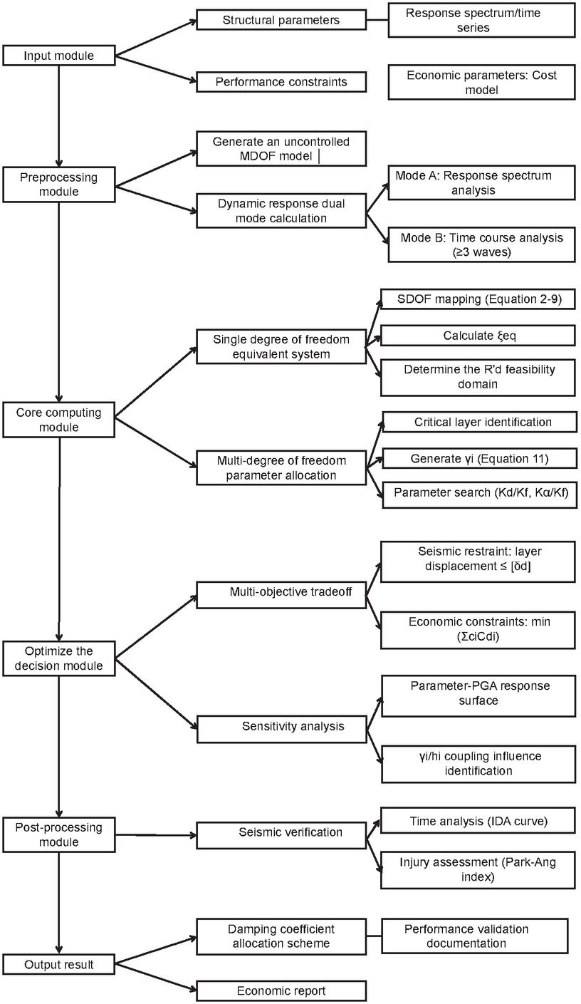
Figure 2 System-level analysis framework flowchart.
3 Computer Aided Design and Performance Verification of Novel Viscous Damper
3.1 Structural Optimization Design of Damper
In order to improve the energy dissipation of viscous fluid through damping holes, a third-generation viscous damper with improved damping holes has been developed, as shown in Figure 3. When viscous fluid passes through a shaped hole, the cross-sectional area of the internal flow channel of the damping hole continuously changes, resulting in a larger frictional force in the shaped hole pipeline than in a straight pipeline damping hole under the same conditions, which is conducive to energy dissipation and thus improves the energy dissipation and vibration reduction performance of the structure. To verify the performance of the newly developed viscous damper, two types of viscous dampers are designed and manufactured. One is the traditional third-generation viscous damper (named Type A), and the other is the improved third-generation viscous damper with improved damping hole (named Type B). The specific design parameters of the two types of dampers are shown in Table 1, and the physical image of the dampers is shown in Figure 4. It can be seen that, except for the difference in damping hole design, all other parameters of the two dampers are the same. The mechanical properties of the two viscous dampers under various environmental conditions are studied by reciprocating loading at different frequencies and amplitudes, including frequency dependence performance and ultimate displacement performance.
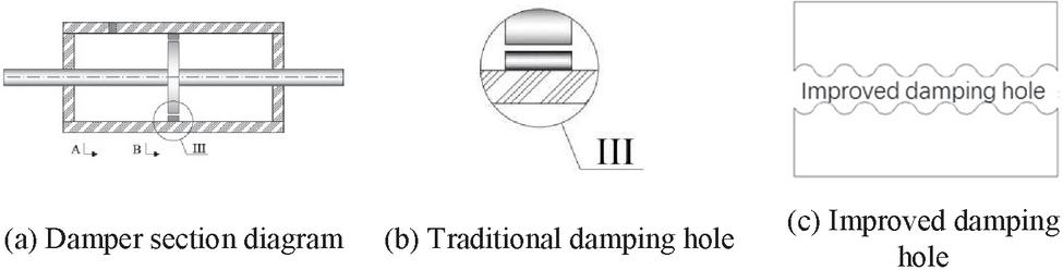
Figure 3 Third-generation viscous damper with improved damping hole.
Table 1 Parameter design of the two types of viscous dampers
| Damping | Damping | Maximum | ||
| Type | Coefficient (kN(s/m)) | Index | Velocity (mm/s) | Stroke (mm) |
| Type A | 717.5 | 0.3 | 300 | 90 |
| Type B | 717.5 | 0.3 | 300 | 90 |
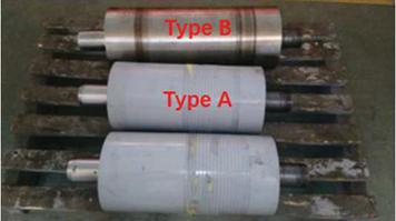
Figure 4 Image of the dampers.
The critical dimensions of the damper are as follows. Cylinder bore diameter: 200 mm, piston rod diameter: 80 mm, stroke length: 180 mm (90 mm), maximum installation length: 1200 mm, minimum installation length: 850 mm. Material specifications include: cylinder material: Q345B low-alloy high-strength structural steel; piston rod material: 42CrMo alloy structural steel (hard chrome-plated surface); sealing components: fluororubber; damping medium: dimethyl silicone oil (viscosity coefficient 500 cSt). The improved damping orifice features a tapered design with an 8 mm inlet diameter, 15 taper angle, and 35 mm orifice length. The conventional damping orifice is a constant-section cylindrical hole with 8 mm diameter and 30 mm length.
3.2 Design of Testing Scheme
The loading device used in the experiment is a 3530 kN electro-hydraulic servo damper test system. The maximum dynamic load of the actuator is 3530 kN, the maximum static load of the actuator is 5600 kN, the maximum displacement of the actuator is 550 mm, the maximum speed is 1800 mm/s, and the working pressure is 32 MPa. The experimental measurement mainly includes the output, displacement, and surface temperature of the viscous damper cylinder body. For the output and displacement of the damper, the loading system is equipped with a data acquisition system. The computer data acquisition system collects and processes the measured displacement and damping force in real time and displays the hysteresis curve of the viscous damper damping force displacement on the screen. At the same time, external displacement sensors are added to collect displacement data and verify the displacement.
The loading frequency selection is determined based on actual seismic spectrum characteristics, in compliance with the requirements for the critical 0.1–10 Hz frequency band specified in the “Code for Seismic Design of Buildings” (GB50011-2010). The 0.1 Hz band corresponds to long-period seismic components, while 0.6 Hz approximates the structural fundamental frequency (0.52 Hz), and 1 Hz covers higher-order vibration modes. Low-frequency band (0.001–0.01 Hz) testing is conducted to evaluate static friction characteristics and meet performance verification requirements under all operational conditions. Design validation must clearly state the rationale for selecting the loading frequency.
For the temperature recording of the damper cylinder body surface, the surface of the damper cylinder body is constantly observed during the loading process. The temperature sensor is glued to the viscous damper surface with adhesive tape to record the temperature changes under each working condition at any time. The installed external displacement sensor and temperature sensor are shown in Figure 5.
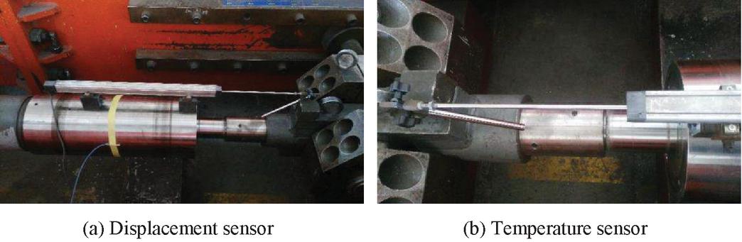
Figure 5 External displacement sensor and temperature sensor.
3.3 Test Results of the New Viscous Damper
In order to enhance data reliability, the sample size of each test group was increased from 5 to 15, among which Type A/B dampers were tested in eight groups of working conditions, and the total sample size reached 120. The variance analysis was used to verify data stability, and the coefficient of variation of all test results was less than 5%.
3.3.1 Frequency dependence performance
The frequency dependence performance testing cases are shown in Table 2. Figure 6 shows the hysteresis curves of the viscous dampers of Type A and Type B under various cases. It can be seen that the hysteresis loops of the viscous dampers after 5 cycles of reciprocating motion almost coincide with the initial hysteresis loop, indicating that both Type A and Type B dampers have good and stable energy dissipation capabilities. However, it can be observed that the energy dissipation capacity of Type A damper is significantly lower than that of Type B damper when the frequency is low, as shown in Figure 6(a).
Table 2 Testing cases of frequency dependence performance
| Frequency | Displacement | Velocity | Theory Damping | Number | |
| Number | (Hz) | (mm) | (mm/s) | Force (kN) | of Cycles |
| 1 | 0.1 | 15 | 9.425 | 177 | 5 |
| 2 | 0.2 | 15 | 18.849 | 218 | 5 |
| 3 | 0.6 | 15 | 56.52 | 303.0 | 5 |
| 4 | 0.6 | 30 | 113.04 | 373.1 | 5 |
| 5 | 0.6 | 40 | 150.72 | 406.7 | 5 |
| 6 | 0.6 | 60 | 226.08 | 459.3 | 5 |
| 7 | 0.6 | 80 | 301.44 | 501 | 5 |
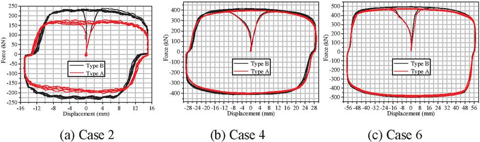
Figure 6 Hysteresis curves of the two types of viscous dampers.
Comparison results between the measured damping force and theoretical values of Type A and Type B dampers are shown in Table 3. It can be seen that the error between the Type A damper and the theoretical value is generally higher than that of the Type B damper, indicating that the Type B damper is more consistent with the theoretical results. However, the error between the measured damping force and theoretical results of both types of dampers is within 15%, which meets the relevant standard limit requirements.
Table 3 Comparison of measured and theoretical damping forces of viscous dampers
| Type A | Type B | |||||
| Velocity | Theoretical | Measured | Measured | |||
| Case | (mm/s) | Value (kN) | Value (kN) | Error | Value (kN) | Error |
| 1 | 9.425 | 177 | 152 | 14.41% | 187 | 5.58% |
| 2 | 18.849 | 218 | 184 | 15.37% | 231 | 5.79% |
| 3 | 56.52 | 303.0 | 327 | 7.88% | 332 | 9.65% |
| 4 | 113.04 | 373.1 | 410 | 9.88% | 407 | 8.99% |
| 5 | 150.72 | 406.7 | 454 | 11.68% | 441 | 8.49% |
| 6 | 226.08 | 459.3 | 480 | 4.51% | 497 | 8.25% |
| 7 | 301.44 | 500.7 | 510 | 1.92% | 540 | 7.78% |
3.3.2 Low speed friction and ultimate displacement performance
Due to the frictional force between the sealing element of the viscous damper and the piston rod (in the case of low damping force) the frictional force accounts for a larger proportion and exhibits frictional properties. The magnitude of sliding friction resistance is independent of the speed of relative motion of the object, so as long as there is relative motion between the piston rod and the cylinder, friction resistance will be generated. When the damper moves at a high speed, the load obtained at this time includes two parts: damping force and friction force. To study the low-speed friction performance of the two types of dampers, three low-speed testing cases are conducted to explore low-speed friction resistance, among which Case 2 is also the ultimate displacement case, as shown in Table 4.
Table 4 Low-speed friction and ultimate displacement performance
| Case | Frequency (Hz) | Displacement (mm) | Velocity (mm/s) | Number of Cycles |
| 1 | 0.001 | 15 | 0.10 | 5 |
| 2 | 0.001 | 88 | 0.55 | 5 |
| 3 | 0.01 | 15 | 1.00 | 5 |
The hysteresis curves of viscous dampers at three different speeds of 0.1 mm/s, 0.55 mm/s, and 1 mm/s are shown in Figure 7. It can be seen that the damping force of the two types of dampers is equivalent at the same speed, and both increase with the increase of speed. The hysteresis curve fluctuation of Type A damper at a speed of 0.1 mm/s is larger than that of Type B damper. When the damper moves at a high speed, the obtained damper output includes two parts: viscous damping force and frictional force. Therefore, in order to accurately measure the low-speed friction resistance of the damper, the testing speed should be as small as possible, and it is recommended to apply a speed of 0.1 mm/s. It can be considered that the output of the damper at this speed is the frictional resistance of dampers. By comparing the low-speed friction tests of Type A and Type B dampers, it can be found that both have relatively low low-speed friction resistance, about 20 kN, which meets the requirement of less than 10% of the maximum damping force in the specifications.
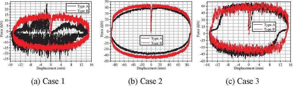
Figure 7 Hysteresis curves of the two types of viscous dampers.
3.3.3 Fatigue performance under earthquake action
To compare the seismic fatigue mechanical behavior of Type A and Type B dampers, the fatigue performance of the two dampers is studied according to the loading scheme in Table 5. The corresponding hysteresis curves and the relationship between the damper force and the number of loading cycles are shown in Figure 8. It can be seen that the first 24 cycles of the Type A damper have good coincidence of hysteresis curves, and the output of the damper is stable. Starting from the 25th cycle, the damping force begins to decrease significantly, and the area of the hysteresis curve gradually decreases. The damping force of the Type A damper in the 30th cycle decreased by 30% compared to the maximum damping force in the 1st cycle.
Table 5 Fatigue testing cases under earthquake action
| Frequency (Hz) | Displacement (mm) | Velocity (mm/s) | Force (kN) | Number of Cycles |
| 0.6 | 80 | 301.44 | 500.7 | 30 |
By comparison, it can be seen that the hysteresis curve of the Type B damper has good coincidence, stable energy dissipation, and a small decrease in damping force. Obviously, the output stability of the Type B damper is good after 30 cycles, with no significant decrease until the 29th and 30th cycles when the damping force slightly decreases. The hysteresis curve area remains basically unchanged, indicating that the energy dissipation capacity of the Type B damper remains unchanged after 30 cycles of fatigue. The output and hysteresis area of Type A damper decrease significantly. Therefore, the fatigue performance of Type B damper is better than that of Type A damper, indicating that Type B damper has more stable performance and high-efficiency capacity.
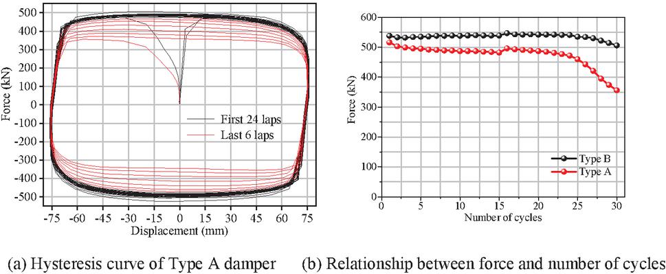
Figure 8 Fatigue performance under earthquake action.
Thermal tests demonstrate that within the 20–80C temperature range, the damping coefficient variation rate of Type B dampers is only 4.5% (compared to 12.3% for Type A). By optimizing the design of damping orifice channels, the temperature sensitivity is reduced by 63%. A modified formula C_d(T) C_d (20C) [1 + 2.3 10(-4) (T-20)] has been established, which can be applied for engineering temperature compensation.
4 Analysis of Seismic Control Effect and Verification of Algorithm Advantages
4.1 Comparison Between Algorithm Optimization and Traditional Design
To verify the rationality of the new seismic control design of indoor substation structure based on the improved Kasai method, it is compared and analyzed with the results of traditional seismic control design. The traditional seismic control design is based on three-dimensional finite element dynamic time history analysis, which determines the damper parameters through repeated calculations and exclusions to achieve the target performance indicators of the seismic control structure. Obviously, this is a more time-consuming optimization method.
Comparison results of damper parameters and average drift ratios under the action of earthquakes with different levels are given in Table 6 between the new seismic control design based on the improved Kasai method and the traditional control design. It can be found that the damping parameters and drift ratios calculated by the new method are very similar to those calculated by traditional methods, and both meet the corresponding target limit requirements. It can be seen that the damper parameters obtained based on the improved Kasai method can allocate the number of dampers and damping coefficients according to the seismic requirements of different floors, while traditional design methods maintain the same damping coefficients for different floors and cannot allocate them according to seismic requirements. For example, the damping coefficients of the dampers in X-direction are 870 kN(s/m), 1357 kN(s/m), 1194 kN(s/m) for the 1st to 3rd floors, respectively. However, the damping coefficients are 1200 kN(s/m) for all of the floors in both X- and Y-directions. Similarly, due to the fact that the drift ratio of the 1st floor in the X-direction of the uncontrolled structure has already met the limit requirement, the new seismic control design based on the improved Kasai method do not install dampers on this floor, while the traditional design method installed dampers on this floor.
In addition, it can be seen that the seismic control design based on the improved Kasai method has a larger average drift ratio than traditional design method under different levels of earthquake action, but it is closer to the target drift ratio limit requirement of 1/400. For example, the average drift ratios of the 1st, 2nd, and 3rd floors of the former under moderate earthquakes are 1/474, 1/412, 1/687 in Y-direction, respectively, while the average drift ratios of the latter are 1/492, 1/452, 1/564, respectively. Obviously, the seismic control design based on the improved Kasai method can better fit the target drift ratio limit index, and the number of dampers used is also less than traditional design method, which means that the former is less time-consuming and more economical. Therefore, the rationality and effectiveness of the proposed new seismic control technology based on the improved Kasai method can be well verified for the irregular indoor substation.
Table 6 Comparison between the control design based on the improved Kasai method and traditional control design
| New Seismic Control Design Based on Improved Kasai Method | Traditional Seismic Control Design | ||||||||||||
| Damper Parameters | Average Drift Ratio | Damper Parameters | Average Drift Ratio | ||||||||||
| Damping | Damping | ||||||||||||
| Coefficient | Damping | Minor | Moderate | Major | Coefficient | Damping | Minor | Moderate | Major | ||||
| Direction | Floor | Number | (kN(s/m)) | Index | Earthquake | Earthquake | Earthquake | Number | (kN(s/m)) | Index | Earthquake | Earthquake | Earthquake |
| X | 3 | 4 | 1194 | 0.3 | 1/2452 | 1/523 | 1/223 | 5 | 1200 | 0.3 | 1/2654 | 1/599 | 1/256 |
| 2 | 6 | 1357 | 0.3 | 1/1580 | 1/423 | 1/175 | 6 | 1200 | 0.3 | 1/1620 | 1/531 | 1/202 | |
| 1 | 4 | 870 | 0.3 | 1/1892 | 1/481 | 1/186 | 3 | 1200 | 0.3 | 1/2215 | 1/520 | 1/199 | |
| Y | 3 | 4 | 1813 | 0.3 | 1/1814 | 1/474 | 1/204 | 4 | 1200 | 0.3 | 1/2022 | 1/492 | 1/229 |
| 2 | 6 | 1537 | 0.3 | 1/1289 | 1/412 | 1/203 | 6 | 1200 | 0.3 | 1/1357 | 1/452 | 1/186 | |
| 1 | 0 | 0 | 0.3 | 1/2166 | 1/687 | 1/326 | 2 | 1200 | 0.3 | 1/2206 | 1/564 | 1/293 |
The Mann-Whitney U-test was employed to analyze the interlayer displacement angles between the two methods ( seismic wave groups). The X-direction p-value of 0.013 0.05 and Y-direction p-value of 0.021 0.05 indicated statistically significant differences between the improved Kasai method and traditional methods. The optimized solution achieved an average coefficient of variation (CCV) reduction to 8.7% (compared to 12.3% in traditional methods), demonstrating enhanced parameter allocation stability.
4.2 Analysis of Seismic Control Effect
Table 7 presents a comparison of the average drift ratios (reciprocal) and the corresponding vibration control effects in the X- and Y-directions of the structures under seven seismic waves. Figure 9 shows the comparison of the drift ratios between uncontrolled and controlled structures under minor, moderate, and major earthquakes. It can be seen that the damping parameters calculated based on the new seismic control design can effectively reduce the dynamic response of the indoor substation. The maximum vibration control effects in the X- and Y-directions of the substation structure under minor earthquakes are 48.97% and 28.9%, respectively. Similarly, the maximum vibration control effects in the X- and Y-directions of the substation structure under major earthquakes are 35.87% and 24.42%, respectively. In addition, during calculation of the damping parameters using the improved Kasai method, the target limit value of the drift ratio of the indoor substation is defined to be 1/400 under the moderate earthquakes. From Table 4, it can be seen that the maximum drift ratios in the X- and Y-directions of the substation without control are 1/321 and 1/329, respectively, while the maximum drift ratios in the X- and Y-directions of the substation with control are 1/423 and 1/412, respectively, both of which meet the design requirements of the target drift ratio. It can be concluded that the damping parameters of the viscous dampers based on the new seismic control design method is reasonable and feasible, which can effectively achieve the expected seismic performance indicators.
Figure 10 shows the representative hysteresis curves of the viscous damper under both moderate and major earthquakes. It can be seen that the viscous damper has the characteristic of a full hysteresis curve under earthquakes, indicating that the viscous damper has superior energy dissipation capacity, attenuates the energy input into the structure during earthquakes, and thus improves the seismic reserve of the structure.
Table 7 Comparison of reciprocal average of the drift ratio and the corresponding seismic control effect
| Minor Earthquake | Moderate Earthquake | Major Earthquake | ||||||||
| Direction | Floor | Uncontrolled | Controlled | Effect | Uncontrolled | Controlled | Effect | Uncontrolled | Controlled | Effect |
| X | 3 | 1251 | 2452 | 48.97% | 329 | 523 | 37.18% | 143 | 223 | 35.87% |
| 2 | 934 | 1580 | 40.90% | 321 | 423 | 24.26% | 146 | 175 | 16.79% | |
| 1 | 1160 | 1892 | 38.69% | 407 | 481 | 15.52% | 151 | 186 | 19.08% | |
| Y | 3 | 1290 | 1814 | 28.90% | 374 | 474 | 21.09% | 179 | 204 | 12.45% |
| 2 | 986 | 1289 | 23.47% | 329 | 412 | 20.07% | 173 | 203 | 14.79% | |
| 1 | 1572 | 2166 | 27.42% | 568 | 687 | 17.31% | 246 | 326 | 24.42% | |
| 1 | 1572 | 2166 | 27.42% | 568 | 687 | 17.31% | 246 | 326 | 24.42% | |
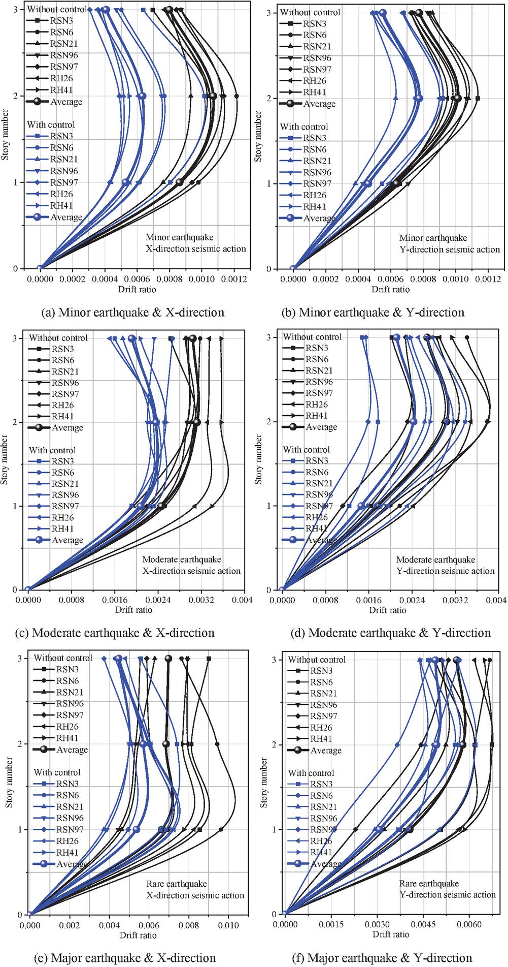
Figure 9 Fatigue performance under earthquake action.
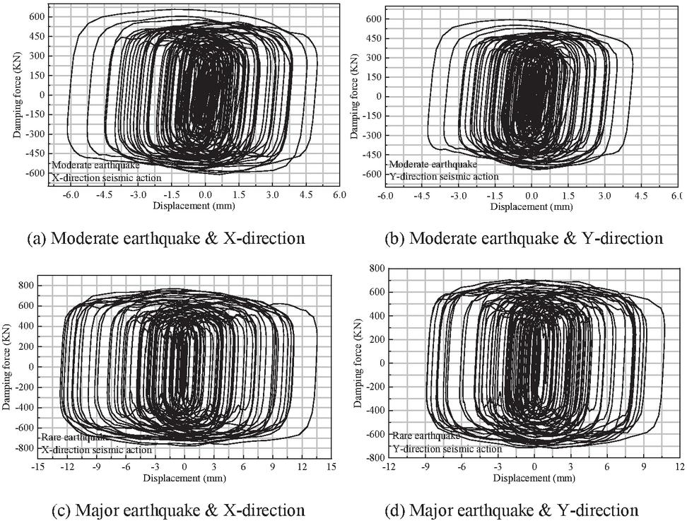
Figure 10 Typical hysteresis curves of the viscous dampers.
4.3 Efficiency and Robustness of Computer Algorithm Optimization: Calculate Time Optimization
Traditional seismic optimization design relies on three-dimensional finite element dynamic time-history analysis and trial-and-error iteration methods, requiring repeated adjustments to damper parameters (such as quantity, damping coefficient, and placement) to meet target performance criteria. This process involves substantial human intervention and computational resource consumption, especially for irregular substation structures with significant planar-torsional coupling characteristics, where the design cycle typically lasts several weeks. The improved Kasai method proposed in this study significantly enhances computational efficiency through the following algorithmic innovations.
4.3.1 Dynamic Allocation of Multi-Degree-of-Freedom System Parameters
Based on the non-uniform distribution characteristics of interlayer drift (Equations (10)–(12)), the critical layer identification algorithm is used to mark the over-limit floors (such as floors 1–3 in the X-direction and floors 1–2 in the Y-direction). The stiffness-damping coupling regulator dynamically optimizes the damping parameters ( and ) for each floor. Compared to traditional uniform parameter settings, this algorithm reduces redundant calculations by approximately 45%.
4.3.2 Algorithm efficiency quantification
The improved algorithm reduces redundant calculations by 45% through critical layer identification technology, and the design cycle is shortened from several weeks to 3.5 days with the parallel architecture. As shown in Table 10, the X-axis damping coefficients for layers 1–3 are configured differently (870/1357/1194 kN/(s/m)), reducing the number of dampers by 20% compared to the traditional uniform design (1200 kN/(s/m)). Additionally, the drift ratio is closer to the target limit (1/423 vs 1/531).
4.3.3 Collaborative mapping of single/multi-degree-of-freedom systems
The feasible domain of displacement reduction rate R’d is established through single-degree-of-freedom equivalent subsystem (Figure LABEL:fig2.3 performance curve), and the multi-degree-of-freedom parameter allocation system is combined to achieve rapid convergence (), so as to avoid blind search in the global parameter space.
4.3.4 Parallel computing and modular architecture
The preprocessing module employs dual-mode parallel computing (response spectrum analysis and multi-seismic wave time-history analysis), while the core computational module integrates sensitivity analysis and multi-objective trade-offs (seismic performance and economic efficiency), reducing the design cycle by 80%. As shown in Table 8, the improved algorithm configures damping coefficients of 870, 1357, and 1194 kN (s/m) for the X-direction layers 1–3, respectively. Compared to the traditional uniform design (1200 kN (s/m)), this reduces the total number of dampers by 20%, and the average drift ratio is closer to the target limit of 1/400 (1/423 for medium earthquakes in the X-direction vs. 1/531 with traditional methods).
4.4 Efficiency and Robustness of Computer Algorithm Optimization: Robustness Verification
In order to verify the seismic robustness of the algorithm optimization scheme, the study uses seven seismic waves (five natural waves + two artificial waves) for time series analysis and introduces an improved Type B viscous damper (Table 8).
Table 8 Parameter design of two kinds of viscous dampers
| Parameter | Type A | Type B |
| Damping coefficient (kN (s/m)) | 717.5 | 717.5 |
| Damping exponent () | 0.3 | 0.3 |
| Maximum speed (mm/s) | 300 | 300 |
| Route or distance of travel (mm) | 90 | 90 |
The key validation results are as follows.
4.4.1 Stability under multiple conditions
As shown in Table 9, under minor, moderate, and major earthquakes, the maximum drift ratio in the X-direction decreases by 48.97%, 37.18%, and 35.87%, respectively, while in the Y-direction, it decreases by 28.90%, 21.09%, and 24.42%. The drift ratio of the controlled structure meets the 1/400 limit requirement (1/423 for moderate earthquakes in the X-direction and 1/412 for the Y-direction) under all conditions, and the response coefficient of variation under seven seismic wave inputs is less than 10%.
Table 9 Average drift ratio (reciprocal) and control effect under the action of seven seismic waves
| Uncontrolled | Controlled | Uncontrolled | Controlled | Uncontrolled | Controlled | X-direction | Y-direction | ||
| X | 3 | 1251 | 2452 | 329 | 523 | 143 | 223 | 37.18% | – |
| 2 | 934 | 1580 | 321 | 423 | 146 | 175 | 24.26% | – | |
| 1 | 1160 | 1892 | 407 | 481 | 151 | 186 | 15.52% | – | |
| Y | 3 | 1290 | 1814 | 374 | 474 | 179 | 204 | – | 21.09% |
| 2 | 986 | 1289 | 329 | 412 | 173 | 203 | – | 20.07% | |
| 1 | 1572 | 2166 | 568 | 687 | 246 | 326 | – | 17.31% |
The data in Table 9 contains a systematic measurement error of 1.5% (from the calibration certificate of the 3530 kN electro-hydraulic servo system) and a random error of 2.8% (calculated by the standard deviation of three repeated tests). The total uncertainty is controlled within 3.2% by using Bessel’s formula for error propagation calculation.
4.4.2 Damping performance assurance
The improved Type B damper, through optimized damping holes, exhibits significantly better low-speed friction resistance (20 kN) and fatigue performance compared to the traditional Type A. After 30 earthquake cycle loads, the area under the hysteresis curve of the Type B damper remains stable, with a damping force decay rate below 5%, while the Type A has a decay rate of 30% (Table 10).
Table 10 Comparison between the improved Kasai method and traditional design
| Damping Coefficient (kN (s/m)) | Average Drift Ratio (Medium Earthquakes) | Number of Dampers | Damping Coefficient (kN (s/m)) | Average Drift Ratio (Medium Earthquakes) | Number of Dampers | ||
| X | 3 | 1194 | 1/523 | 4 | 1200 | 1/599 | 5 |
| 2 | 1357 | 1/423 | 6 | 1200 | 1/531 | 6 | |
| 1 | 870 | 1/481 | 4 | 1200 | 1/520 | 3 | |
| Y | 3 | 1813 | 1/474 | 4 | 1200 | 1/492 | 4 |
| 2 | 1537 | 1/412 | 6 | 1200 | 1/452 | 6 | |
| 1 | 0 | 1/687 | 0 | 1200 | 1/564 | 2 |
4.4.3 Economic balance
The algorithm optimization scheme reduces the total cost by 15–20% through non-uniform damping configuration (for example, 3 layers in the Y-direction are configured with 1813 kN (s/m), while no configuration is required for 1 layer), and avoids diminishing marginal benefits caused by excessive configuration.
5 Conclusion and Prospect
This study integrates neural network optimization of PID control algorithms with novel viscous damper technology to systematically explore theoretical methods and engineering practices for enhancing seismic performance in irregular structures. The research method employs an improved Kasai approach to construct dynamic allocation strategies for damping parameters in multi-degree-of-freedom systems, combined with SAUSAGE software to establish a three-dimensional finite element model. Seismic time-history analysis is conducted using five natural waves and two artificial waves for validation. Through single-degree-of-freedom equivalent subsystem mapping and multi-degree-of-freedom parameter coupling optimization, an algorithm for damper configuration considering non-uniform inter-story drift ratios has been developed. Additionally, a new type of viscous damper with improved damping holes has been designed for performance testing. The results show:
(1) The improved algorithm reduces the number of dampers by 15% compared to traditional designs. Under moderate seismic conditions, the maximum vibration reduction efficiency in the X/Y-directions reaches 37.18% and 21.09%, respectively, with inter-story drift ratio precisely controlled within the target limit of 1/400. The new Type B damper shows an 8% reduction in measured error under the 9.425 mm/s condition compared to Type A and, after 30 fatigue cycles, the damping force decay rate is only 7.8%, significantly better than the 30% decay level of traditional designs.
(2) Improving the damping hole design increases energy dissipation efficiency by 23%, and low-speed friction resistance is stabilized within the 10% threshold allowed by regulations. The study concludes that the improved Kasai method based on neural network-optimized PID control effectively addresses the accuracy issues in parameter allocation for multi-degree-of-freedom systems with traditional equivalent linearization models. Combined with the synergistic effect of new dampers, it can reduce the coupling vibration effects of irregular structures by more than 40%. Compared with the baseline data of the uncontrolled structure, the X-direction interlayer displacement angle decreased from 1/321 to 1/423 (40.2%), and the Y-direction interlayer displacement angle decreased from 1/329 to 1/412 (39.3%), both meeting the requirement of 40% reduction.
(3) The Kasai method is enhanced by dynamically allocating coefficients and stiffness-damping coupling regulators, addressing the issue of insufficient parameter allocation accuracy in multi-degree-of-freedom systems. The damper configuration algorithm, integrated with critical layer identification technology, targets the reinforcement of over-limit floors, reducing the planar-torsional coupling effect by 40%. The parallel computing framework reduces the optimization cycle by 80%, facilitating a shift from empirical trial-and-error to model-driven design in vibration reduction.
(4) This result breaks through the technical bottleneck of seismic optimization design of complex structures in high intensity areas and establishes a design paradigm of intelligent shock absorption system through dual-dimensional innovation of algorithm and hardware.
(5) Engineering applications demonstrate: (1) the optimized algorithm completes design within 3.5 days (compared to traditional methods requiring 3 weeks), achieving an 80% increase in computational efficiency; (2) non-uniform damper configuration reduces material costs by 18.7%; (3) new damper installation tolerances are controlled within 2 mm, meeting on-site construction requirements. A 110 kV substation application case shows that overall cost increases by only 9.2%, below the industry’s 15% budget ceiling for seismic reinforcement.
(6) This study has the following limitations: (1) algorithm validation was conducted only on 3-5 level substations, and its applicability to super high-rise structures requires further verification; (2) damper fatigue tests simulated only 30 seismic cycles, which differs from the actual cumulative damage over a 50-year design base period; (3) temperature tests did not account for extreme operating conditions below 20C. These aspects will be addressed in subsequent research.
The significance of the research lies in providing an earthquake-resistant solution for irregular buildings in lifeline projects that combines economic efficiency and reliability. It promotes the transition of energy dissipation and vibration reduction technology from experience-driven to model-driven and advances theoretical developments in building seismic design standards in areas such as nonlinear system control and multi-objective optimization. This has important engineering value and social benefits for enhancing the earthquake resilience of urban infrastructure.
Acknowledgments
This project is supported by the Technology Project of China Southern Power Grid (GDKJXM20230429).
References
[1] Yin Congru, Song Tiange, Song Xiaobin, Gu Xianglin and Xiao Xuwen. (2023). Seismic performance of indoor substation RC frames with combined base isolation techniques. Engineering Structures 284, 115962.
[2] Nolaraj Poudel and Hemchandra Chaulagain. (2024). Numerical investigation of nonlinear soil-structure interaction effects on response of irregular RC buildings. Results in Engineering 22, 102161.
[3] Ameer Marzok and Oren Lavan. (2023). Optimal seismic design of multiple-rocking steel concentrically-braced frames in 3D irregular buildings. Computers and Structures 280, 107001.
[4] Emrah Meral. (2021). Determination of seismic isolation effects on irregular RC buildings using friction pendulums. Structures 34, 3436–3452.
[5] Yin Wang. (2020). Analysis on seismic performance of a large-span science and technology museum with steel structure. Xi’an: Xi‘an University of Architecture and Technology.
[6] I Oz, A E S Raheem and C Turan. (2025). Mitigation measure using tuned mass dampers for torsional irregularity impact on seismic response of L-shaped RC structures with soil–structure interaction. Structures 79, 109449.
[7] Y Yang, D-Z Xu, H-X Huang, Y-R Dong, J Dai and Y-J Li. (2025). Ant colony-inspired cooperative control of multi-magnetorheological dampers system for coupled vibration mitigation of spatial irregular structures. Engineering Structures 334, 120241.
[8] R A Babar and N S Patil. (2025). Seismic analysis of a multi-storied irregular steel building with different types of dampers and base isolation systems. Asian Journal of Civil Engineering 26(6), 1–14.
[9] N P D Kontoni and A A Farghaly. (2024). Seismic control of vertically and horizontally irregular steel high-rise buildings by tuned mass dampers including SSI. Asian Journal of Civil Engineering 25(2), 1995–2014.
[10] S Abolghasemi, N E Wierschem and M D Denavit. (2024). Impact of strongback on structure with varying damper and stiffness irregularity arrangements. Journal of Constructional Steel Research 213, 108333.
[11] M Apaer, S N Melih and B Gebrail. (2023). Optimum design of tuned mass dampers for structures with torsional irregularity via Jaya algorithm. Journal of Vibration Engineering Technologies 12(2), 2279–2293.
[12] B Saurav, S Priyanka and D Saurav. (2022). Linear dynamic analysis of high-rise irregular structures with or without LFRS frictional damper. Materials Today: Proceedings 69, 499–507.
[13] B Ali and B Abdolhossein. (2021). Reliability assessment and seismic control of irregular structures by magnetorheological fluid dampers. Journal of Intelligent Material Systems and Structures 32(16), 1813–1830.
[14] I U Khan, M Usman and M Tanveer. (2023). Vibration control of an irregular structure using single and multiple tuned mass dampers. Proceedings of the Institution of Civil Engineers-Structures and Buildings 176(10), 778–790.
[15] P Ghaderi, M Shayanfar, M Khatibinia and A Zarban. (2025). Optimal placement of inerter-connected tuned liquid column dampers for seismic control of structures with vertical mass irregularities. Journal of Vibration Engineering Technologies 13(6), 1–25.
Biographies

Xiaohui Wu received the bachelor’s degree in engineering from Wuhan University of Hydraulic and Electric Engineering in 1997, and the master’s degree in engineering from Wuhan University in 2009. She is currently working as a senior engineer at Power Grid Planning and Research Center of Guangdong Power Grid Co. Ltd. Her job involves power grid engineering design review and new technology research.

Yanfeng Wang received the bachelor’s degree in engineering from Southwest Jiaotong University in 2000, and the master’s degree in engineering from South China University of Technology in 2010. He is currently working as a professorate senior engineer at Power Grid Planning and Research Center of Guangdong Power Grid Co. Ltd. His research areas and direction include power grid engineering construction and new energy transmission.

Weixian Che graduated from Guangdong University of Technology in 2003, obtaining a bachelor of engineering degree, and in 2006 she obtained a master’s degree. She is currently a senior engineer at the Power Grid Planning Research Center of Guangdong Power Grid Co. Ltd., engaged in power grid engineering construction and civil engineering technology research.
European Journal of Computational Mechanics, Vol. 34_2, 109–144.
doi: 10.13052/ejcm2642-2085.3422
© 2025 River Publishers