A Parametric Study of Elastic Web Buckling in Steel Plate Girders with Transverse Stiffeners
Emina Hajdo1, Emina Hadzalic2,* and Adnan Ibrahimbegovic3, 4
1University of Sarajevo-Faculty of Civil Engineering, Patriotske lige 30, 71000 Sarajevo, Bosnia and Herzegovina
2University of Rijeka, Faculty of Civil Engineering, Radmile Matejčić 3, 51000 Rijeka, Croatia
3University of Technology of Compiègne, Laboratoire Roberval, rue du docteur Schweitzer, 60203 Compiègne, France
4Institut Universitaire de France, 1 rue Descartes, 75231 Paris, France
E-mail: emina.hajdo@gf.unsa.ba; emina.hadzalic@uniri.hr; adnan.ibrahimbegovic@utc.fr
∗Corresponding Author
Received 25 July 2025; Accepted 25 September 2025
Abstract
This study presents a numerical investigation into the elastic buckling behaviour of steel plate girders with transverse stiffeners, focusing on the web buckling mode. The influence of key parameters, including web thickness, stiffener thickness and spacing, and flange-stiffener connectivity, is examined to understand their effect on the critical buckling load associated with this mode. Elastic buckling analyses are carried out for various combinations of these parameters using a finite element model based on a nonlinear shell element formulation, which incorporates von Kármán-type nonlinear strain-displacement relations to effectively capture geometric nonlinearities and local instability phenomena. The results are systematically presented and discussed to highlight the sensitivity of buckling performance to each parameter. Detailed insights are provided into the underlying structural behaviour, revealing trends and interactions that govern the elastic web stability of steel plate girders with transverse stiffeners across different design configurations.
Keywords: Steel plate girder, transverse stiffener, web buckling, shell finite element, geometric nonlinearities, elastic critical buckling load.
1 Introduction
Steel plate girders are widely used in the construction of bridges, buildings, and other large-scale structures due to their high strength-to-weight ratio, which allows them to support significant vertical loads over long spans. A key consideration in the design of steel plate girders is ensuring their stability against buckling, which can result in sudden failure. Among the different buckling modes, web shear buckling is a particularly significant concern in slender girders. In girders with thick webs, web failure will generally occur due to shear yielding before buckling develops. However, thin webs with higher slenderness ratios will fail primarily through buckling, before reaching the yield strength. Therefore, ensuring sufficient shear buckling resistance to maintain web stability is among the fundamental aspects of steel plate girder design.
The shear buckling resistance in steel plate girders is typically enhanced through the use of transverse stiffeners and, in some cases, supplemented by longitudinal stiffeners [1, 2] although, in certain instances, increasing the web thickness is preferred to avoid the additional fabrication costs associated with stiffeners. Transverse stiffeners are installed perpendicular to the flanges of a steel plate girder and are generally connected to the web, whereas their connection to the flanges varies depending on specific design requirements and construction practices. These stiffeners help delay the onset of buckling by redistributing the stresses within the web [3]. Transverse stiffeners are generally classified as end or intermediate stiffeners. End stiffeners, also referred to as bearing stiffeners, are placed at both ends of the girder to transfer loads to the supports and prevent local web failure. Intermediate stiffeners are provided between supports, especially in regions of concentrated loads or high shear stresses. They are essential when the web is slender, as they improve the buckling resistance by dividing the web into smaller panels, thereby reducing the panel aspect ratio [4].
The performance of intermediate stiffeners is influenced by their spacing and thickness. Intermediate stiffeners in steel plate girders are typically classified as either rigid or non-rigid, depending on their ability to restrain out-of-plane deformation of the web [5]. A stiffener is considered rigid if it can effectively restrain the transverse displacements of the web at the junction of the stiffener and web, maintaining its straight configuration even during the post-buckling stage. In contrast, non-rigid stiffeners, while still contributing to the strength and stiffness of the web, tend to deform and buckle along with the web [6]. This classification is typically based on stiffness criteria, most often expressed in terms of the required moment of inertia and/or cross-sectional area [7]. The distinctions in performance between these two types of stiffeners necessitate different approaches in the design of steel plate girders. For rigid stiffeners, well-established guidelines provided by codes such as Eurocode 3, Part 1-5 for plated structural elements [8] and AASHTO [9] include detailed provisions for determining the shear buckling resistance, typically based on methods such as the rotated stress field method, the simple post-critical method, or the tension field method [10]. However, for non-rigid stiffeners, such guidance is not provided and, instead, finite element eigenvalue analysis is recommended to assess the critical buckling load of the stiffened web plate [6].
According to Eurocode 3, Part 1-5 [8], and AASHTO [9] guidelines, the shear buckling resistance of the web is determined by adding a certain amount of the post-buckling strength to the elastic buckling strength. Therefore, an accurate assessment of elastic buckling strength, considering all influencing factors such as web slenderness and stiffener configuration, is essential for the reliable design of steel plate girders [11]. While code-based provisions offer simplified approaches to determine the elastic buckling strength, they may not fully reflect the influence of detailed geometry and boundary conditions. Finite element models, on the other hand, offer a more comprehensive representation of steel plate girders, enabling a more accurate analysis of buckling phenomena that may not be adequately captured by design formulations.
Numerical models based on the geometrically exact beam finite elements are widely used to analyse the global stability of steel plate girders due to their efficiency in capturing overall structural behaviour under large displacements and rotations [12, 13, 14, 15, 16]. In addition to beam-based models, finite element models using shell elements are frequently used [17, 18, 19], as they offer a more detailed representation of girder geometry and enable the analysis of local instabilities and buckling behaviour within individual components, such as the web and flanges. In such models, stiffeners are typically modelled using shell elements. However, when shell elements with drilling degrees of freedom (rotations about the normal to the shell surface) are employed for modelling the steel plate girder [20, 21, 22, 23], stiffeners can alternatively be represented as beam elements without significantly compromising the accuracy of the results [24].
In this paper, we investigate the elastic shear buckling behaviour of the web in steel plate girders with transverse stiffeners through a detailed parametric study using finite element modelling. Building upon our previously developed and validated model based on a shell element formulation capable of capturing geometric nonlinearities and local instability phenomena [24], this study extends its application further to examine the influence of key parameters such as web thickness, stiffener thickness and spacing, and flange-stiffener connectivity on the elastic critical buckling load.
The outline of the paper is as follows: Section 2 outlines the geometrically nonlinear shell element formulation, which provides the foundation for analysing the web buckling behaviour. Section 3 describes the finite element model of a representative steel plate girder and presents the details of the numerical parametric study, focusing on the effects of key parameters such as web thickness, stiffener spacing and thickness, and flange-stiffener connectivity on the elastic critical buckling load. This section also discusses the corresponding numerical results. Finally, Section 4 summarizes the main findings of the study.
2 Geometrically Nonlinear Shell Finite Element Formulation
The theoretical foundation for the nonlinear shell element, which forms the basis of the finite element model used to analyse the elastic critical buckling load in this study, is developed by superimposing the contributions of the Reissner–Mindlin plate element [25, 26] and membrane element with drilling degrees of freedom [27, 28], with the formulation further extended to include simplified nonlinear strain-displacement relations to account for geometric nonlinearity. In the following, we outline the main features of the nonlinear shell element. For more details, we refer to [24]. In the present study, both the steel plate girder and stiffeners are represented by the same shell element.
2.1 Stress Resultants and Deformation Measures
The nonlinear shell element is formulated by superimposing the contributions of the plate bending behaviour and membrane action. Accordingly, the stress resultants vector consists of the bending moment and transverse shear force resultants from the plate component, along with in-plane force resultants from the membrane component (Figure 1), written as
| (1) |
Here, denotes the vector of bending moment resultants, where and represent the bending moments in the - and -directions, and is the twisting moment; the vector represents the transverse shear force resultants, with components and corresponding to the transverse shear forces; and denotes the membrane force resultants vector, where and are the normal membrane forces in the - and -directions, and is the shear membrane force.
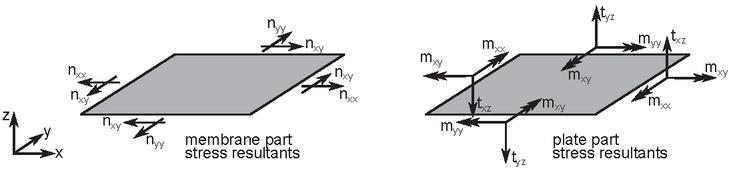
Figure 1 Stress resultants in the shell element: membrane and plate contributions.
The corresponding stress resultants for the plate part are computed as
| (2) |
where is the curvature vector, with , , and representing the curvatures in the -, -, and twisting directions, respectively; is the transverse shear deformation vector, with and denoting the transverse shear deformations; and and are the corresponding linear elastic constitutive matrices, defined as
| (3) |
where is the Young’s modulus, is the Poisson’s ratio, and is the thickness of the element.
According to the linear theory, the curvatures and transverse shear deformations are defined as
| (4) |
where , , and are the displacements along the -, - and - axes, respectively; and and are the rotations about the - and - axes.
The stress resultants for the membrane part are computed as
| (5) |
where is the vector of in-plane (membrane) deformations derived using the linear theory, and is the corresponding linear elastic constitutive matrix, defined as
| (6) |
To include geometric nonlinearity under the assumptions of small strains and moderate rotations, the membrane deformations are formulated using von Kármán-type nonlinear strain-displacement relations. These relations extend the classical linear formulation by including additional nonlinear terms [29, 30, 31]. Accordingly, the membrane deformations are defined as follows
| (7) |
where represents the membrane deformations according to the linear theory, and denotes the nonlinear contribution.
2.2 Finite Element Formulation
To develop the finite element formulation, we begin by deriving the weak form of the governing equations using the principle of virtual work. This approach requires the introduction of a virtual displacement vector, denoted by , which is defined as follows
| (8) |
where are the virtual translational displacements in the -, -, and - directions, and are the virtual rotations about the same axes.
The virtual deformation measures for the plate part are defined as
| (9) |
The virtual von Kármán deformations are derived by applying the directional or Gâteaux derivative in the direction of the virtual displacements, resulting in
| (10) | ||
With the virtual displacements and their associated deformation measures defined, the virtual work of the internal forces, consisting of contributions from both membrane and plate actions, can be expressed as
| (11) |
Finally, the weak form for the nonlinear shell element can be defined as
| (12) | ||
where represents the distributed surface load, denotes the edge (line) loads, and corresponds to the concentrated loads.
To discretize the weak form for numerical implementation, a flat four-node quadrilateral shell element is introduced, in accordance with the standard finite element approximation procedure. Each node of the element has six degrees of freedom, three translational and three rotational, as illustrated in Figure 2. The initial formulation excludes the drilling rotation (), which is incorporated subsequently. The remaining displacement components are interpolated using standard linear isoparametric shape functions for a four-node element, defined as
| (13) | ||
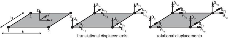
Figure 2 Degrees of freedom of a shell element.
Hence, the remaining displacement components are expressed using the previously defined shape functions as follows
| (14) |
where
| (15) | ||
with as the matrix of shape functions, given as
| (16) | ||
Furthermore, linear membrane deformations, the curvatures, and shear deformations can be expressed as
| (17) | |
where is the vector of nodal displacements including drilling rotation degree of freedom , and , and are the associated matrices of derivatives of the shape functions, given as
| (18) | ||
| (19) | ||
| (20) | ||
| (21) | ||
By combining previous results, an overall matrix of derivatives of shape functions for a four-node flat shell element can be expressed as
| (22) |
Then, the first part of the virtual work of internal forces in Equation (12) can be reformulated as
| (23) |
from which the material contribution to the element stiffness matrix is obtained as
| (24) |
where is the overall constitutive matrix, given as
| (25) |
What remains is to include the contribution of the drilling rotation [20] in the finite element formulation for the nonlinear shell element. A detailed formulation for incorporating the drilling rotation can be found in [32, 27]. Here, we provide only the final expression for the membrane contribution to the material stiffness matrix, given as
| (26) |
where is the material dependent factor, which serves as a stabilization parameter for drilling rotations [33], and and are matrices of derivatives of shape functions, defined as
| (27) | ||
where and are the nodal coordinates of the element.
The geometric part of the stiffness matrix is obtained from the second term of the virtual work of internal forces in Equation (12), which can be rewritten as
| (28) |
where represents the nonlinear contribution to the membrane deformations, with denoting its virtual counterpart, is the associated matrix of derivatives of the shape functions, and is the matrix of the membrane forces, given as
| (29) | ||
Finally, the geometric part of the element stiffness matrix can be defined as
| (30) |
3 Parametric Study
This section presents the results of a numerical parametric study on the elastic web shear buckling behaviour of a typical steel plate girder with transverse stiffeners, focusing on the influence of web thickness, the thickness and spacing of stiffeners, and the connectivity between the stiffeners and flanges. All numerical implementations and computations were performed using the research version of the computer code FEAP (Finite Element Analysis Program), developed by R. L. Taylor [34].
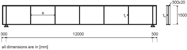
Figure 3 Geometry of the analysed steel plate girder.
The girder is modelled based on the adopted geometry shown in Figure 3. The total length of the girder is with a web height of and flange dimensions of . The material properties of steel are defined by a Young’s modulus of and a Poisson’s ratio of . The girder is laterally braced to prevent lateral torsional buckling and subjected to a uniformly distributed load along the entire span.
The effect of web thickness , stiffener thickness , and stiffener spacing on the elastic critical buckling load is investigated. For each combination of the varied parameters, two separate analyses were performed: one assuming that the stiffeners are connected to both the web and the flanges, and another assuming they are connected only to the web, with no connection to the flanges.
The computed buckling loads presented in Figures 4–7 for various stiffener spacings indicate that an increase in web thickness significantly enhances the critical buckling load across all analysed cases. Even a relatively small increase in web thickness can substantially improve buckling capacity. For instance, with a stiffener thickness of , increasing the web thickness from to results in an increase in the critical buckling load of approximately to , depending on the stiffener spacing.
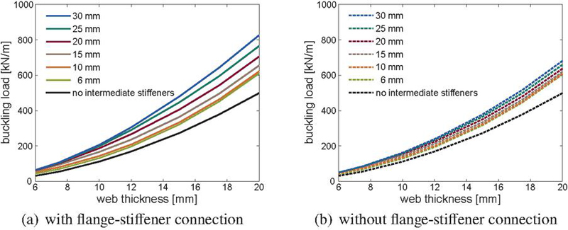
Figure 4 Influence of web and stiffener thickness on the critical buckling load, .
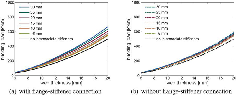
Figure 5 Influence of web and stiffener thickness on the critical buckling load, .
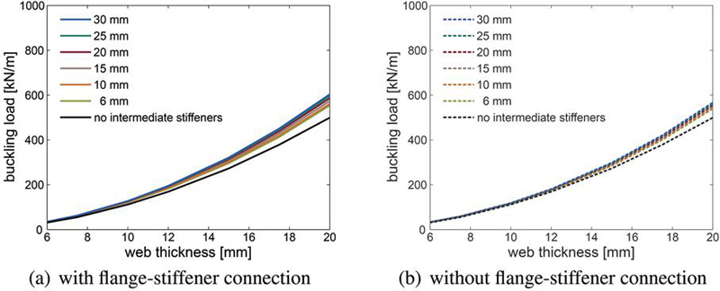
Figure 6 Influence of web and stiffener thickness on the critical buckling load, .
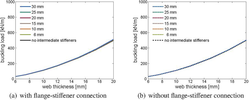
Figure 7 Influence of web and stiffener thickness on the critical buckling load, .
The computed results further show that increasing the thickness of stiffeners contributes positively to the buckling resistance of the web when the spacing between stiffeners is small. However, as the spacing increases, the influence of stiffener thickness on the critical buckling load gradually decreases. A comparison with the case without intermediate stiffeners (unstiffened case) shows that at the largest spacing of , the stiffeners no longer contribute to the buckling resistance of the web, regardless of their thickness.
At smaller stiffener spacings ( and ), the effect of stiffener thickness on the critical buckling load is more pronounced when the stiffeners are connected to both the web and the flanges. As the spacing between stiffeners increases, the influence of flange connectivity on the critical buckling load becomes less significant, since the overall contribution of the stiffeners to buckling resistance diminishes.
To better illustrate the previously discussed results, the computed critical buckling loads for a web thickness of are presented in Figures 8 and 9, plotted against stiffener spacing and thickness, respectively. The computed results clearly show that the influence of stiffener thickness is significantly more pronounced at smaller spacings for both configurations, with and without flange-stiffener connectivity. However, for the case without the flange-stiffener connection, increasing the stiffener thickness at smaller spacings leads to a less pronounced increase in the critical buckling load. These findings indicate a notable interaction between the stiffeners thickness and spacing, emphasizing the necessity for their combined optimization in practical design.
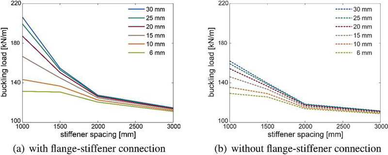
Figure 8 Influence of stiffener spacing on the critical buckling load, .
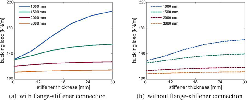
Figure 9 Influence of stiffener thickness on the critical buckling load, .
Figure 10 shows the first buckling mode shapes of a steel plate girder with a web and stiffener thickness of , corresponding to configurations that include a flange-stiffener connection. At the smallest stiffener spacing of , the first buckling mode does not occur in the panel adjacent to the support but rather in regions closer to mid-span, indicating an interaction between shear and normal stress components. In contrast, for all other analysed stiffener spacings, the first buckling mode is localized in the web panels near the supports, where shear stresses predominate.
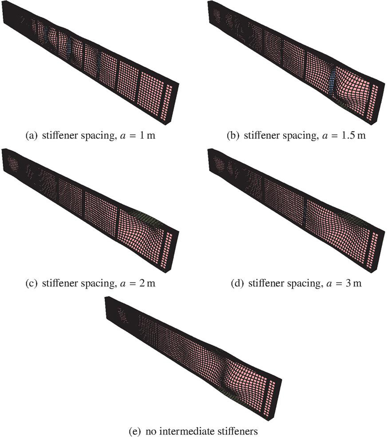
Figure 10 First buckling modes of the analysed steel plate girder with a web and stiffener thickness of , with flange-stiffener connection.
We further investigate how flange thickness influences the contribution of the flange-stiffener connection to the critical buckling load. The analysis is performed for varying flange thickness, with web and stiffener thickness set to . The results presented in Figure 11 indicate that the contribution of the flange-stiffener connection to the critical buckling load remains nearly constant across all flange thickness values and stiffener spacings analysed. However, as the stiffener spacing increases, this contribution diminishes.
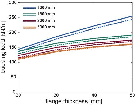
Figure 11 Influence of flange thickness on the contribution of the flange-stiffener connection to the critical buckling load, ; dashed lines indicate no flange-stiffener connection.
As evident from the presented results, the increase in the flange thickness contributes to the increase in the computed critical buckling load. Still, the contribution of the flanges must be explicitly considered [35, 36, 37], as they can only contribute to the buckling resistance if they are not fully engaged in resisting bending moments. While the influence of the flanges on buckling resistance is often small and can often be neglected, it becomes significant when strong flanges are used or when they are not fully utilized in resisting bending moments, such as in regions near the end supports [6]. However, this influence is outside the scope of this study and will not be commented on further.
3.1 Discussion in Light of Eurocode 3, Part 1-5 Guidelines
The elastic critical shear buckling stress or elastic buckling strength represents the basis for assessing the stability of the web according to the provisions of Eurocode 3, Part 1-5 [8]. According to these provisions, the elastic buckling stress can be computed as [3]
| (31) |
where is the shear buckling coefficient calculated from elastic buckling theory [3, 38], and is the height of the web. The shear buckling coefficient for plates with rigid transverse stiffeners, under the assumption that the web panel is simply supported on all sides, can be determined as follows
| (32) | ||
For unstiffened webs, the shear buckling coefficient is equal to .
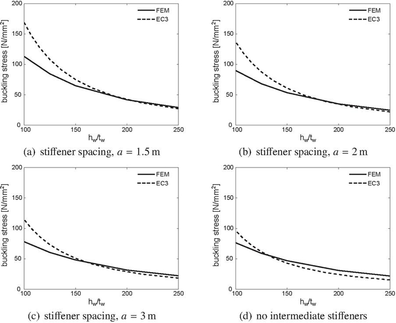
Figure 12 Comparison of critical elastic buckling stresses.
The numerically obtained elastic buckling stresses are compared with analytical values computed using Equations (31) and (32), as shown in Figure 12. The numerical elastic buckling stresses are calculated by dividing the maximum shear force at the support, resulting from the critical buckling load obtained in the finite element model, by the cross-sectional area of the web, representing the average shear stress on the section. The comparison is provided for the case without intermediate stiffeners and for stiffener spacings of , , and . The presented numerical results correspond to the case with the maximum transverse stiffener thickness of and with the flange-stiffener connection. These results pertain to the buckling mode occurring in the panel adjacent to the support, where the shear force predominates.
It is important to note that the elastic buckling stress calculated using Equations (31) and (32) corresponds to a pure shear stress state and simply supported boundary conditions along all edges of the web panel. Consequently, this analytical model differs from the numerical model in terms of boundary conditions and stress state. Specifically, the numerical model accounts for the true geometry of the steel plate girder and considers a typical loading scenario of a uniformly distributed load over the entire span. Thus, the comparison of the analytical and numerical results is provided solely to illustrate how the real-case scenario relates to the outcomes of the analytical model, which forms the basis for determining the design shear resistance according to the Eurocode 3, Part 1-5 guidelines.
The comparison of results shows that the numerical model produces slightly higher elastic critical buckling stress than the analytical expressions at higher slenderness ratios. However, at lower slenderness ratios, the numerically obtained values tend to be lower. As the stiffener spacing increases, the discrepancies between the numerical and analytical results decrease at lower slenderness ratios but tend to increase moderately at higher slenderness ratios. Furthermore, increasing the stiffener spacing shifts the transition point between over-prediction and under-prediction of the elastic critical buckling stress toward lower slenderness ratios.
The presented comparison highlights the importance of accurately determining the elastic critical buckling load, as it directly influences the stability assessment of the web. An imprecise evaluation may result in conservative designs or unsafe conditions, emphasizing the need for comprehensive analyses that consider all the key factors influencing the elastic buckling behaviour of the web in steel plate girders with transverse stiffeners. Comparable findings concerning the design shear buckling resistance of the web are documented in [39].
4 Conclusions
This numerical study investigated the elastic web buckling behaviour of steel plate girders through a detailed parametric analysis that considered variations in web thickness, transverse stiffener thickness and spacing, and flange-stiffener connectivity. The numerical analyses were performed using finite element modelling with shell elements, accounting for geometric nonlinearity. Based on the obtained results, the following general conclusions can be drawn:
• Web thickness is the most influential parameter affecting the elastic critical buckling load. Even a relatively small increase in web thickness leads to significant improvements in buckling resistance, highlighting the dominant role of web slenderness in stability analysis.
• Stiffener thickness contributes positively to increasing the elastic buckling resistance, particularly at smaller stiffener spacings. However, its effect gradually diminishes as the spacing increases, becoming negligible for wider panels.
• The presence of flange-stiffener connectivity enhances the overall stability of the web panel, especially when stiffeners are sufficiently thick and closely spaced. As stiffener thickness decreases or spacing increases, the influence of flange connectivity on the critical buckling load becomes less significant.
• A notable interaction between stiffener thickness and spacing was observed, indicating that these parameters should be considered together during the design process. At small to intermediate spacings (e.g., or less), the difference in buckling load between thin and thick stiffeners remains considerable, while at larger spacings (e.g., and above), this difference becomes marginal.
The findings of this study emphasize the importance of considering all key factors that influence the elastic buckling strength, as it directly governs the stability assessment of webs in transversely stiffened steel plate girders.
Funding
This work was supported by the Institut Universitaire de France (IUF), under Grant no. 1479 (A.I.).
Conflicts of Interest
The authors declare no conflicts of interest.
References
[1] M M Alinia. (2005). A study into optimization of stiffeners in plates subjected to shear loading. Thin-Walled Structures, 43(5), 845–860.
[2] Sérgio Nascimento, José J Oliveira Pedro, Rafael Santos and Ulrike Kuhlmann. (2023). Experimental behaviour of plate girders in steel–internal forces in intermediate transverse stiffeners. Engineering Structures, 291, 116425.
[3] Stephen P Timoshenko and James M Gere. (2012). Theory of Elastic Stability. North Chelmsford: Courier Corporation.
[4] Sung C Lee, Doo S Lee and Chai H Yoo. (2014). Design of intermediate transverse stiffeners for shear web panels. Engineering Structures, 75, 27–38.
[5] Sérgio Nascimento, Rafael Santos and José Oliveira Pedro. (2022). Behaviour of plate girders with intermediate transverse stiffeners–experimental investigation. ce/papers, 5(4), 675–684.
[6] Bernt Johansson, René Maquoi, Gerhard Sedlacek, Christian Müller, Darko Beg, et al. (2007). Commentary and worked examples to EN 1993-1-5 Plated structural elements. JRC Scientific and Technical Reports.
[7] Franc Sinur and Darko Beg. (2012). Intermediate transverse stiffeners in plate girders. Steel Construction, 5(1), 23–32.
[8] European Committee for Standardization. (2004). Eurocode 3: Design of Steel Structures – Part 1-5: Plated structural elements. EN 1993-1-5:2004.
[9] American Association of State Highway and Transportation Officials. (1996). Standard specifications for highway bridges.
[10] José J Oliveira Pedro, Sérgio Nascimento and Chris Hendy. (2024). Shear buckling resistance models for plate girders–review and improvements. Engineering Structures, 307, 117857.
[11] Zaid Al-Azzawi, Timothy Stratford, John Rotter and Luke Bisby. (2015). Effect of flange and stiffener rigidity on the boundary conditions and shear buckling stress of plate girders. 15th European Bridge Conference & Exhibition. ECS Publications.
[12] Adnan Ibrahimbegović. (1995). On finite element implementation of geometrically nonlinear Reissner’s beam theory: three-dimensional curved beam elements. Computer Methods in Applied Mechanics and Engineering, 122(1–2), 11–26.
[13] Anisio Andrade, Dinar Camotim and P Borges Dinis. (2007). Lateral-torsional buckling of singly symmetric web-tapered thin-walled I-beams: 1D model vs. shell FEA. Computers & Structures, 85(17–18), 1343–1359.
[14] R F Vieira, F B E Virtuoso and E B R Pereira. (2017). Buckling of thin-walled structures through a higher order beam model. Computers & Structures, 180, 104–116.
[15] Rodrigo Goncalves. (2019). An assessment of the lateral-torsional buckling and post-buckling behaviour of steel I-section beams using a geometrically exact beam finite element. Thin-Walled Structures, 143, 106222.
[16] Hamed Farokhi and Mergen H Ghayesh. (2019). A new geometrically exact model for buckling and postbuckling statics and dynamics of beams. Journal of Applied Mechanics, 86(7), 071001.
[17] Sándor Ádány. (2012). Global buckling of thin-walled simply supported columns: Analytical solutions based on shell model. Thin-Walled Structures, 55, 64–75.
[18] Sheng Jin, Zhanjie Li, Fang Huang, Dan Gan, Rui Cheng and Gaofeng Deng. (2019). Constrained shell finite element method for elastic buckling analysis of thin-walled members. Thin-Walled Structures, 145, 106409.
[19] Trung Hoang and Sándor Ádány. (2020). The effect of transverse stiffeners on the torsional buckling of thin-walled columns. Proceedings of the Annual Stability Conference Structural Stability Research Council Atlanta, Georgia.
[20] D J Allman. (1984). A compatible triangular element including vertex rotations for plane elasticity analysis. Computers & Structures, 19(1–2), 1–8.
[21] Adnan Ibrahimbegović. (1994). Stress resultant geometrically nonlinear shell theory with drilling rotations–Part I. A consistent formulation. Computer Methods in Applied Mechanics and Engineering, 118(3–4), 265–284.
[22] Adnan Ibrahimbegovic. (1997). Théorie géométriquement exacte des coques en rotations finies et son implantation éléments finis. Revue Européenne des éléments finis, 6(3), 263–335.
[23] D Boutagouga and K Djeghaba. (2014). Geometrically nonlinear dynamic analysis of thin shells by a four-node quadrilateral element with in-plane rotational degree of freedom. European Journal of Computational Mechanics, 23(3–4), 161–177.
[24] Emina Hajdo, Adnan Ibrahimbegovic and Samir Dolarevic. (2020). Buckling analysis of complex structures with refined model built of frame and shell finite elements. Coupled Systems Mechanics, 9(1), 29–46.
[25] Stephen Timoshenko and Sergius Woinowsky-Krieger. (1959). Theory of plates and shells. McGraw-Hill.
[26] T Krauthammer and E Ventsel. (2001). Thin plates and shells: theory, analysis and applications. New York: Marcel Dekker.
[27] Adnan Ibrahimbegovic, Robert L Taylor and Edward L Wilson. (1990). A robust quadrilateral membrane finite element with drilling degrees of freedom. International Journal for Numerical Methods in Engineering, 30(3), 445–457.
[28] Adnan Ibrahimbegović and François Frey. (1995). Variational principles and membrane finite elements with drilling rotations for geometrically non-linear elasticity. International Journal for Numerical Methods in Engineering, 38(11), 1885–1900.
[29] Emina Hajdo, Emina Hadzalic and Adnan Ibrahimbegovic. (2022). Linear buckling analysis of structures on the elastic support. International Symposium on Innovative and Interdisciplinary Applications of Advanced Technologies, 92–102, Springer.
[30] Emina Hajdo, Emina Hadzalic and Adnan Ibrahimbegovic. (2024). Buckling analysis of piles in weak single-layered soil with consideration of geometric nonlinearities. Coupled Systems Mechanics, 13(3), 187–200.
[31] Emina Hajdo, Emina Hadzalic, Emir Karavelić, Naida Ademović and Adnan Ibrahimbegovic. (2024). Effective buckling length analysis in steel frame columns: a comprehensive review and novel approaches. International Symposium on Innovative and Interdisciplinary Applications of Advanced Technologies, 100–114, Springer. Springer.
[32] Adnan Ibrahimbegovic. (2009). Nonlinear Solid Mechanics: Theoretical Formulations and Finite Element Solution Methods, Vol. 160. Springer Science & Business Media.
[33] Thomas J R Hughes and F Brezzi. (1989). On drilling degrees of freedom. Computer Methods in Applied Mechanics and Engineering, 72(1), 105–121.
[34] Robert L Taylor. FEAP – A Finite Element Analysis Program. Available online: http://projects.ce.berkeley.edu/feap/
[35] Leroy Gardner, Andreas Fieber and Lorenzo Macorini. (2019). Formulae for calculating elastic local buckling stresses of full structural cross-sections. Structures, 17, 2–20. Elsevier.
[36] Qianjing Zhang, Lei Zhang, Yujia Zhang, Yufei Liu and Jia Zhou. (2023). Elastic local buckling of I-sections under axial compression incorporating web–flange interaction. Buildings, 13(8), 1912.
[37] Lei Zhang, Qianjing Zhang, Genshu Tong and Qunhong Zhu. (2024). Elastic local buckling and width-to-thickness limits of I-beams incorporating flange–web interactions. Buildings, 14(2), 347.
[38] Philip Stanley Bulson. (1970). The Stability of Flat Plates. London: Chatto & Windus.
[39] André da Silva Reis. (2016). Shear buckling in steel plate girders exposed to fire. Universidade de Aveiro (Portugal): PhD thesis.
Biographies

Emina Hajdo is an Associate Professor at the University of Sarajevo Faculty of Civil Engineering. She completed her PhD at the Faculty of Civil Engineering, University of Sarajevo, and conducted part of her research as a French Government Scholar at École normale supérieure de Cachan (now Paris-Saclay). Her scientific and professional work focuses on the fields of steel structures, structural instability, and computational mechanics.

Emina Hadzalic is an Associate Professor at the Faculty of Civil Engineering, University of Rijeka. She completed her PhD through a joint doctoral program between the University of Technology of Compiègne, France and the University of Sarajevo Faculty of Civil Engineering, Bosnia and Herzegovina. Her research interests include engineering mechanics and computational mechanics.

Adnan Ibrahimbegovic is a Professor of Classe Exceptionnelle and Chair of Computational Mechanics at the University of Technology of Compiègne, France. He is a member of the Academy of Europe and the Academy of Sciences and Arts of Bosnia and Herzegovina. He completed his PhD at the University of California, Berkeley, USA, and later obtained his habilitation from Université Pierre et Marie Curie, France. His research focuses on computational mechanics and multi-physics.
European Journal of Computational Mechanics, Vol. 34_3&4, 275–298
doi: 10.13052/ejcm2642-2085.34344
© 2026 River Publishers