Research on Seismic Mechanical Characteristics of Multi-Story Frame Structures in Prefabricated Buildings
Li Jianwei1, Zhao Yongquan1 and Niu Haoshuang2,*
1Capital Construction Department, Henan Polytechnic University, Jiaozuo 454003, China
2School of Civil Engineering, Henan Polytechnic University, Jiaozuo 454003, China
E-mail: Niuhs0310@126.com
*Corresponding Author
Received 26 August 2025; Accepted 17 November 2025
Abstract
As an important structural form of prefabricated buildings, multi-story frame structures are mainly composed of vertically load-bearing frame columns and horizontally connected beams, featuring good structural stability and strong seismic resistance. Compared with the traditional cast-in-place reinforced concrete frame structure, the core feature of the prefabricated frame lies in that its structural components are prefabricated in the factory and then transported to the site to be assembled into an integral structure through specific connection techniques. This revolutionary change in construction methods, while bringing about improvements in efficiency and quality, has also profoundly altered the force transmission mechanism and failure mode of structures. The key to its seismic performance is largely determined by the performance of the connection nodes between prefabricated components, especially the beam-column nodes. This paper focuses on the seismic mechanical characteristics of multi-story frame structures in prefabricated buildings. Through numerical simulation, the mechanical response features of multi-story frame structures under seismic loads are systematically analyzed. Two different strength grades of concrete show similar trends in bearing capacity and deformation capacity. When the axial compression ratio increases, the bearing capacity and yield displacement of the structure are smaller. When the yield strength of longitudinal reinforcing bars increases, the structure has a higher bearing capacity, initial stiffness and greater yield displacement. It has a stronger adaptability when plastic deformation occurs. Structures with a lower reinforcement ratio have a lower bearing capacity and, as the load increases, the rate at which the bearing capacity decreases is faster.
Keywords: Prefabricated buildings, multilayer frame, frame structure, structural seismic resistance, finite element analysis.
1 Introduction
Seismic design is crucial in modern construction engineering, especially in areas with frequent earthquakes. Enhancing the seismic resistance of building structures is a critical concern for safeguarding the safety of individuals and their property. Although traditional building frame structures have been proven to have certain seismic resistance through years of practice, their limitations in seismic performance gradually become apparent with the increase of earthquake frequency and building height [1]. Especially in some high-seismic areas, traditional buildings often face serious post-earthquake damage problems, making it difficult to meet today’s seismic requirements [2]. Traditional construction methods have problems such as long construction periods, difficult quality control, and serious resource waste during the construction process, and there is an urgent need for a more efficient, environmentally friendly, and sustainable construction methods [3]. Compared with traditional buildings, prefabricated buildings not only have higher precision and shorter construction periods but also improve the variability and seismic resistance of building structures through modular design and flexible component combinations [4]. The application field of prefabricated buildings is gradually expanding, especially in multilayer buildings. Prefabricated frame structures are easy to construct, economically efficient, and have superior seismic performance, which can improve the seismic performance of structures while ensuring building stability [5].
Existing research has shown that prefabricated buildings have superior structural performance compared to traditional buildings, especially in terms of seismic resistance. Prefabricated structures have advantages such as light weight, high strength, and high precision in factory production [6]. However, in specific seismic performance research, the majority of existing literature predominantly examines the seismic performance of single-story or low-rise structures, and there exists a limited body of research concerning the aseismic behavior of multilayer prefabricated frame structures [7]. Prior research [8, 9] has demonstrated that the seismic performance of prefabricated frame structures is affected by various factors, including the methods of component connection, the design of nodes, and the properties of materials. Reasonable design can significantly improve their seismic resistance [10]. Consequently, the investigation of the seismic mechanical properties of multilayer frame structures within prefabricated buildings, as well as an analysis of their performance and benefits when subjected to seismic loads, has emerged as a significant area of contemporary research in the field of building structures [11].
The force transmission efficiency of node connections determines the seismic performance of prefabricated multi-story frames. The widely used bolt connections and grouting sleeve connections have significant differences in force transmission mechanisms: bolt connections transmit force through mechanical interlocking of “point surface contact”, which makes stress easy to concentrate. Under seismic loads, the force transmission efficiency nonlinearly decays quickly and, when the inter-story displacement angle exceeds 1/50, the proportion of slip deformation is high. Although energy can be dissipated by friction, it is difficult to effectively transmit bending moments, and the interface between the connecting plate and the concrete is prone to peeling off. The grouting sleeve connection relies on the coordinated force transmission of “reinforcement grouting material sleeve”, the stress is distributed along the sleeve gradient, and the interlayer displacement angle reaches 1/25, which can still maintain high force transmission efficiency, and the stiffness degradation is slow. However, insufficient grouting density will cause early failure of the bonding interface. Existing research has mostly focused on single-layer or low-rise structures, without considering the coupling effects of axial compression ratio and other parameters on the force transmission mechanism in multilayer structures. There is also a lack of quantitative description of the critical state of force transmission failure under strong earthquakes. This paper will analyze the force transmission response and related parameter effects of two types of connections in multilayer frames through numerical simulation, providing support for node selection and seismic design optimization.
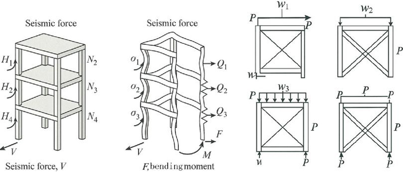
Figure 1 Mechanical analysis of lower frame structure under seismic action.
2 Mechanical Characteristic Analysis of Prefabricated Multilayer Frame Structure
The mechanical behavior of prefabricated concrete frame structures differs significantly from cast-in-place structures, with the core being that the mechanical properties of node connections dominate the overall structural response [12]. The node connection performance deeply influences the mechanical properties of prefabricated multilayer frame structures in terms of bearing capacity, stiffness, stability, and durability [13]. The strength, stiffness, ductility, and durability of node connections directly determine the overall structural transmission efficiency, deformation capacity, stability reserve, and long-term performance [14]. Figure 1 presents mechanical analysis of the lower frame structure under seismic action. In terms of horizontal force, represents the horizontal earthquake/load between the first layer, and is the horizontal force between the i-th layer, used to analyze the horizontal resistance to lateral displacement. In the vertical force, is the vertical axial force (including self weight and live load) of the first layer column/node, and is the axial force of the corresponding part of the upper layer, reflecting the vertical bearing capacity. In terms of shear force, is the horizontal shear force at the end of the first floor beam/column, is the corresponding shear force at the upper level, and and represent the section shear force of the component (such as calculating shear bearing capacity). These symbols collectively quantify the seismic stress and seismic performance of the structure.
2.1 Analysis of the Bearing Capacity Characteristics of Structures
Structural bearing capacity refers to a structure’s capability to withstand external loads without undergoing failure in strength or experiencing instability. The bearing capacity characteristics of prefabricated frames are deeply influenced by the performance of nodes and the collaborative work between components [15].
Nodes are key force transmission hubs between prefabricated components, and their bearing capacity depends on the connection form, material strength, and construction details. The central region of the point experiences intricate composite stress conditions, which encompass axial compression, bending moments, and shear forces [16]. The theoretical framework must be developed with consideration of the concrete failure mechanisms in the node region, the yield characteristics of the reinforcing steel bars, the strength and anchoring capabilities of the connectors, as well as the shear resistance at the joint interface. The interface between new and old concrete joints or between components and connectors is a weak link. The bearing capacity of connecting components such as bolts, welding, grouting sleeves, needs to be theoretically calculated based on material mechanics and connection geometry, taking into account their potential brittle failure under cyclic loading [17].
The theoretical framework for calculating the bending, shear, and compressive bearing capacities of prefabricated beams and columns is fundamentally aligned with that of in-situ construction system elements [18]. Nevertheless, the configuration of the connection necessitates careful consideration of the stress distribution and the possible local failure modes at the extremity of the component. The overall load-bearing capacity of prefabricated frames cannot be regarded merely as the sum of the load-bearing capacities of individual prefabricated components; rather, the load-bearing capacity of the joints typically serves as the critical determinant [19]. The comprehensive evaluation of the overall structural integrity subjected to vertical and horizontal loads necessitates the application of plastic hinge theory. The actual bending and shear resistance of prefabricated nodes may be lower than that of the connected precast beams and columns. This may lead to the early development of plastic hinges or brittle shear failure in the node region, thereby considerably diminishing the ductility and overall load-bearing capacity reserve of the structure. The rigidity and strength of node connections have a direct impact on the efficient transfer of loads within the framework [20]. The incomplete continuity of the connection may lead to deviations between the actual stress state of the structure and the continuous frame calculation model, affecting the accurate evaluation of the overall bearing capacity.
2.2 Analysis of Stiffness Characteristics of Structure
Stiffness refers to a structure’s capacity to withstand deformation, which has a direct impact on its inherent vibrational properties, the management of lateral displacements, and the distribution of internal forces [21]. The semi-rigid connection of nodes is the core characteristic that distinguishes the stiffness of prefabricated frames from cast-in-place frames.
Prefabricated joints are rarely ideal for fully rigid or hinged connections, and typically exhibit semi-rigid behavior. Theoretical analysis requires the establishment or adoption of reasonable nodal mechanics models to quantitatively describe this relationship, such as linear spring models, bilinear models, and multi-parameter power function models [22]. The ability of nodes to resist shear deformation and axial deformation is equally important, especially when subjected to horizontal loads. The ability of a frame structure to resist horizontal loads, such as wind and earthquake loads, mainly depends on its lateral stiffness [23]. In numerical simulations, a bilinear model is used for semi-rigid nodes, which has been proven to more accurately characterize the shrinkage and stiffness degradation behavior of prefabricated connections under cyclic loading.
The joints between components may experience additional opening or sliding deformation under stress, further reducing the overall lateral stiffness of the structure. Node flexibility leads to increased lateral and vertical deflection deformation of the structure under load [24]. In comparison to fully reinforced cast-in-place frames, prefabricated frames exhibit a reduction in the bending moment at the beam ends, while the bending moment at the mid-span is observed to increase. The bending moment at the extremity of the column is also affected by the rotation of the node [25]. Theoretical analysis needs to accurately capture this internal force redistribution effect through structural analysis models that consider node stiffness [26].
3 Numerical Simulation of Seismic Performance of Prefabricated Multi-Story Frame Structure
3.1 Numerical Simulation Model of Framework Structure
In this study, a site characteristic period of 0.4 s corresponds to Class II site conditions. The parameters of soil distribution, stiffness, and damping characteristics under this site category are important foundations for ensuring that the research is in line with the actual site environment of the project. To accurately simulate the stress response of structures under real earthquake action, the selected input seismic waves in the study were professionally screened and amplitude scaled to achieve effective compatibility with the target site characteristic period of 0.4 s on the acceleration response spectrum, thereby ensuring that the seismic action borne by the structure during seismic performance analysis meets the seismic requirements of actual engineering scenarios.
This paper selects the prefabricated multilayer frame structure of a certain factory as the research object. The structure is a four-story building with three spans in the direction from east to west and a duration of 4.5 m, and two segments oriented in the north-south direction and a span of 5.5 m [27, 28]. The floor height is 3.2 meters. The layout plan and column grid dimensions of the structure are presented in Figure 2. The concrete utilized is classified as grade C30, and the floor thickness is 150 mm, which can ensure the comprehensive load-bearing capacity and stability of the building [29, 30]. The seismic group where the structure is located is the second group, with an intensity of fortification measured at 8 degrees (0.2 g), a classification category designated as Class II, and identifies specific periods of site characteristics of 0.4 s. The specific parameter settings are shown in Table 1.
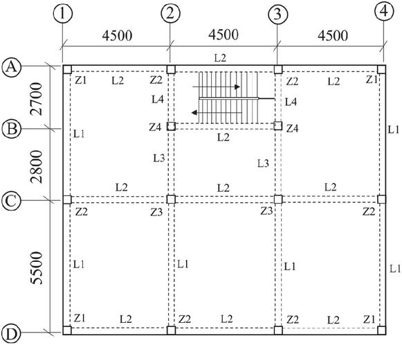
Figure 2 Structural layout plan and column grid size diagram (mm).
Table 1 Cross-sectional dimensions and material characteristics of building components
| Component | Dimension | Material Characteristics |
| Column | 500 mm 500 mm | C30 |
| Main Beam | 250 mm 500 mm | C30 |
| Secondary Beam | 250 mm 500 mm | C30 |
3.2 Results of Numerical Simulation
By using the same reciprocating load, the models of the in-situ frame structure and the prefabricated structural framework under the same conditions are loaded. Through numerical simulation, the load displacement relationship diagrams of the two structures can be obtained, revealing the mechanical response of the structures under seismic loads. During the loading process, the nonlinear behavior of the structure gradually becomes apparent. The load displacement curve, through its bending and changes at different stages, intuitively represents the mechanical characteristics of the structural behavior during the elastic phase, the plastic phase, and ultimate stage, providing detailed performance evaluation for structural seismic design and helping to optimize and improve seismic resistance and safety.
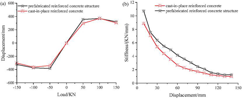
Figure 3 Comparison chart of load-displacement and stiffness-displacement degradation.
From Figure 3(a), it can be seen that the initial seismic resistance of the two structures is relatively close and can withstand similar loads. Prefabricated components and steel bars usually connect the connection area of prefabricated structures. These connection points may experience stress concentration under earthquake action, leading to early entry into the plastic stage. When subjected to load, the bearing capacity of the connection parts shows a significant downward trend. Therefore, although the initial load-bearing capacity of prefabricated structures is strong, the rate of decrease in load-bearing capacity will accelerate under larger loads. Although the prefabricated frame structure has little difference in ultimate bearing capacity compared to cast-in-place structures, its seismic performance shows certain advantages due to its earlier entry into the plastic stage and higher ductility coefficient. Especially during earthquakes, structures can absorb and dissipate energy through ductility, avoiding brittle failure and improving overall seismic safety [31].
From Figure 3(b), it is evident that the prefabricated structural framework adopts prefabricated components, which usually have high initial stiffness and can maintain the deformation resistance of the structure well when facing external loads. The stiff degradation of cast-in-place structures is relatively fast, which is related to the significant plastic deformation and local buckling that may occur in their components during the stress process. Due to the use of prefabricated components and optimized connection methods, prefabricated structures can effectively slow down the degradation rate of stiffness within a certain range. This slowed-down degradation process indicates that prefabricated frame structures have better resistance to deformation when facing loads and can maintain high structural stability [32]. However, under extreme loads or large deformations, the final stiffness performance of prefabricated structural framework structures and in-situ casting frame structures is similar, reflecting their similar performance under extreme load conditions. Due to the good maintenance of stiffness, prefabricated structures can effectively resist deformation caused by loads and exhibit a high level of performance in seismic design of buildings. By optimizing design and material selection, prefabricated frame structures can maintain long-term structural stability while meeting load-bearing requirements.
4 Analysis of Factors Affecting the Seismic Performance of Prefabricated Multi-Story Frame Structures
This study employs finite element modeling to investigate various factors affecting the seismic mechanical performance of prefabricated multilayer frame structures, facilitating a comprehensive analysis of the subject. The research primarily investigates the impact of various factors, including concrete strength, axial compression ratio, longitudinal reinforcement strength, and longitudinal reinforcement ratio of beams, on the seismic performance of structures subjected to identical seismic conditions. The parameter conditions for the finite element model are presented in Table 2. This study primarily investigates the variations in bearing capacity, stiffness, story drift, and story drift angle of the structure by simulating its structural response under various parameter conditions. The alteration of the axial compression ratio can influence both the bearing capacity and deformation characteristics of the frame structure, subsequently impacting the structural response during seismic events. The longitudinal strength of steel reinforcement and concrete plays a critical role in determining the seismic resistance of a structure. Additionally, the ratio of steel reinforcement influences the ductility and energy dissipation capacity of the structural system. This series of analyses offers a theoretical foundation for the seismic design of prefabricated multilayer frame structures, facilitating the optimization of design parameters and enhancing the seismic performance and safety of these structures.
Table 2 Finite element model parameter conditions
| Axial | Strength of | Longitudinal | ||
| Concrete | Compression | Longitudinally | Reinforcement | |
| Model | Strength | Ratio | Stressed Steel Bars | Ratio |
| Model 1 | C40 | 0.35 | HRB400 | 622 |
| Model 2 | C30 | 0.35 | HRB400 | 622 |
| Model 3 | C40 | 0.2 | HRB400 | 622 |
| Model 4 | C40 | 0.35 | HRB335 | 622 |
| Model 5 | C40 | 0.35 | HRB400 | 620 |
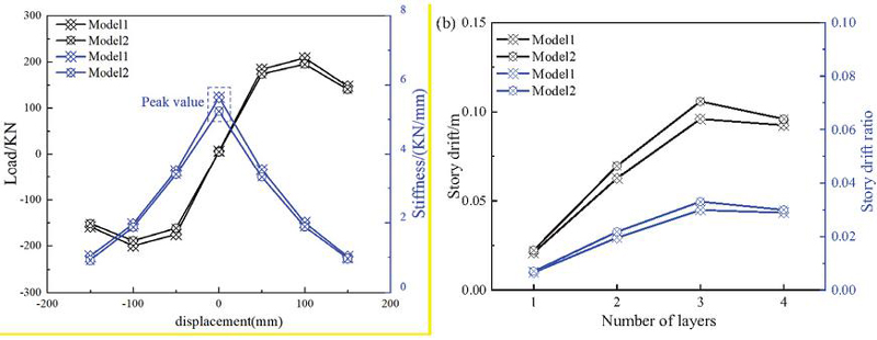
Figure 4 Bearing capacity and inter-story displacement angle of the structure under different concrete strengths.
4.1 Influence of Concrete Strength Grade
Figure 4(a) illustrates that, despite variations in concrete strength grades (C30 and C40) and some observable minor discrepancies, the two strength grades exhibit similar trends in terms of bearing capacity and deformation capacity. This means that within a certain range, changes in the strength grade of concrete do not significantly alter the maximum bearing capacity or initial stiffness of the nodes. By comparison, it can be found that there are some slight differences in the stiffness degradation process between Model 1 and Model 2 concrete strength grades, but the overall trend is similar. This indicates that the strength classification of concrete is unlikely to exert a substantial influence on the aseismic behavior of the structure. Therefore, when designing nodes, the selection of concrete strength grade should mainly consider the requirements of the specifications and its matching with the steel reinforcement grade, meeting the minimum requirements in the design specifications, avoiding unnecessary material costs, and ensuring the economic and structural integrity and safety.
An analysis of the story drift and story drift angle between the two models presented in Figure 4(b) reveals that the maximum story drift of the frame exhibits a consistent growth trend across varying concrete strengths. The maximum story drift of the frame utilizing C30 concrete strength is measured at 0.11 meters, whereas the maximum story drift for the frame employing C40 concrete strength is recorded at 0.096 meters. In comparison, the maximum story drift of the frame utilizing C40 concrete strength exhibited a reduction of 12.72%. The maximum story drift angle of the frame, observed at various concrete strengths, is recorded on the third floor. Specifically, the maximum story drift angle for the frame utilizing C30 concrete strength is 1/29, while for C40 concrete strength, it is 1/33, indicating a reduction of 12.12%. The inter-story drift angle of C40 frame is reduced by 12.12%, which is significantly close to and fully complies with the allowable drift limit of multi-story frame structures under frequent earthquakes in GB 50011 standard, directly proving that its seismic performance has been effectively improved.
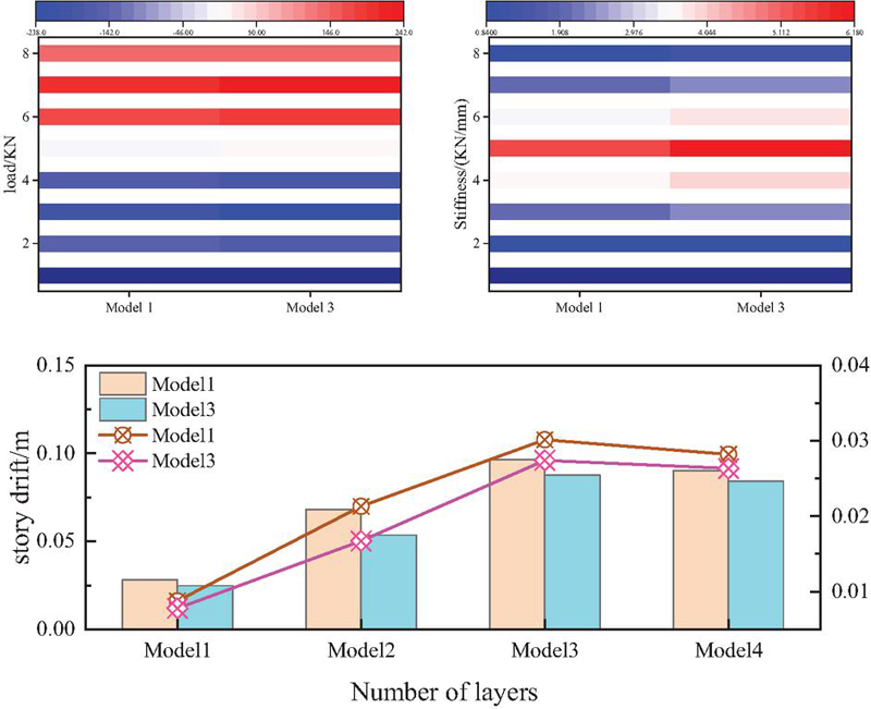
Figure 5 Bearing capacity and inter-story displacement angle of the structure under different coaxial compression ratios.
4.2 Impact of Axial Compression Ratio
As illustrated in Figure 5, an increase in the axial compression ratio is observed. The skeleton curve of Model 1 exhibits lower bearing capacity and smaller yield displacement compared to Model 3, indicating that Model 3 has stronger adaptability and better deformation performance when bearing large loads. The increase in the axial compression ratio leads to a reduction in the compressive capacity of the structure, resulting in diminished stiffness during the initial loading phase. This alteration may have implications for the seismic performance of the structure. An increase in the axial compression ratio leads to a marked acceleration in the rate of stiffness degradation of the structure, particularly following the attainment of its maximum bearing capacity. The stiffness degradation of Model 1 is faster than that of Model 3, indicating the elevation of the axial compression ratio expedites the deterioration of stiffness within the structure, which may affect the ductility performance of the structure. The accelerated stiffness degradation rate may also make the structure unable to maintain sufficient stiffness and stability under extreme loads, and it is prone to instability or failure. During the design process, it is essential to judiciously determine the axial compression ratio in accordance with the specific load requirements and the operational environment of the structure. This approach is necessary to achieve an optimal balance in the overall performance of the structure.
Figure 5(b) quantitatively discusses the stiffness degradation of prefabricated frames through visualized data. The line chart further indicates that as the number of floors increases, the increase in inter-story displacement angle of Model 1 is significantly greater than that of Model 3 (especially on higher floors, where Model 1’s displacement angle reaches about 0.75–0.90 m, while Model 3 is always controlled at a lower level). The bar chart directly compares the displacement angle values between the two layers, and the displacement angle of Model 1 is generally higher than that of Model 3, verifying that its stiffness degradation rate is faster. These data collectively indicate that Model 1 experiences accelerated stiffness degradation due to an increase in axial compression ratio, resulting in a more significant displacement response under load, thereby affecting the ductility and stability of the structure. This highlights the importance of controlling the axial compression ratio reasonably for the seismic performance of prefabricated frames.
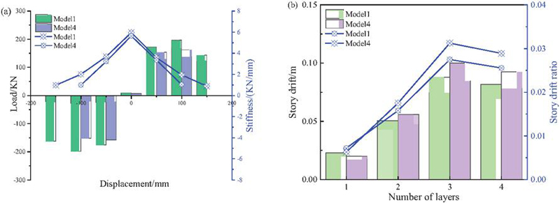
Figure 6 Bearing capacity of the structure and the inter-story displacement angle when the strength of the longitudinally stressed reinforcing bars is different.
4.3 Influence of Longitudinal Stress on the Strength of Steel Bars
From Figure 6(a), it is evident that an increase in the yield strength of the longitudinal reinforcement bars is observed; the skeleton curve of Model 1 exhibits higher bearing capacity, initial stiffness, and greater yield displacement. In the analysis model, HRB400 steel bars are evenly distributed throughout all longitudinal beams and column components on all floors. This means that the structure can withstand greater loads and has stronger adaptability when plastic deformation occurs. Comparing the stiff degradation curves, it was found that regardless of how the tensile strength of the longitudinal bars changes, the stiffness degradation process of the two structural models during the preliminary loading phase is similar. In the stage of decreasing capacity, the stiffness degradation rate of Model 1 structure is significantly slower than that of Model 4. This indicates that longitudinal bars with high yield strength can effectively delay the stiffness degradation of the structure, enhance its seismic performance and durability. This phenomenon further proves the advantages of high-yield-strength steel bars in long-term structural use, especially in the face of large loads or extreme loads such as earthquakes, where the structure can maintain good stiffness and bearing capacity. Therefore, in the design process, the yield strength of longitudinal steel bars should be judiciously determined in accordance with the specific load demands and safety criteria pertinent to the structure, to ensure the balance and excellent performance of the structure in terms of bearing capacity, ductility, and durability.
The analysis of story drift and story drift angle presented in Figure 6(b) indicates that the maximum story drift of the structural framework in Model 4 exhibits a markedly greater growth trend compared to that of Model 1. The maximum story drift observed in the structural framework of Model 1 is 0.088 meters, while Model 4 exhibits a maximum story drift of 0.1 meters, representing an increase of 13.6%. The maximum story drift angle for the Model 1 structural framework is 1/36, whereas for the Model 4 structural framework it is 1/32, indicating an increase of 12.5%.
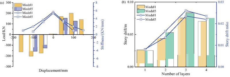
Figure 7 Bearing capacity and inter-story displacement angle of the structure when the longitudinal reinforcement ratio is different.
4.4 Impact of Longitudinal Steel Reinforcement Ratio
From Figure 7(a), it can be seen that Model 5 structures with lower reinforcement ratios have lower bearing capacity and, as the load increases, the rate of decrease in bearing capacity is faster than Model 1. This means that, under the same load, the structural performance of Model 5 is not as stable as Model 1 and is prone to plastic deformation at an earlier stage. From the stiffness degradation curve, it can be seen that Model 5 structures with lower reinforcement ratios experience faster stiffness degradation and exhibit stronger energy dissipation capabilities. This may be due to the significant deformation of the structure during the failure process, resulting in a reduction of the overall load-bearing capacity. In the design process, the reinforcement ratio should be reasonably selected to ensure the balance of the structure in terms of bearing capacity, and stiffness degradation, to guarantee the structural integrity and cost-effectiveness of the design.
From the comparison of story drift and story drift angle between the two models in Figure 7(b), it is evident that the growth pattern of the maximum story drift of the frame exhibits similarities, regardless of variations in the longitudinal steel reinforcement ratio. The maximum story drift observed in the Model 1 structural frame is 0.075 meters, whereas the Model 5 structural frame exhibits a maximum story drift of 0.083 meters. In contrast, the maximum story drift of the Model 1 structural frame has decreased by 9.64%. The maximum story drift angle of the structural frame, observed under varying concrete strengths, is recorded on the third floor, the maximum story drift angle for the Model 1 structural frame is measured at 1/43, while the Model 5 structural frame exhibits a maximum story drift angle of 1/39. This represents an increase of 10.26%.
Therefore, in practical design, a balanced reinforcement ratio should be selected to ensure sufficient energy dissipation capacity while controlling the degradation of bearing capacity, taking into account seismic safety and economic feasibility.
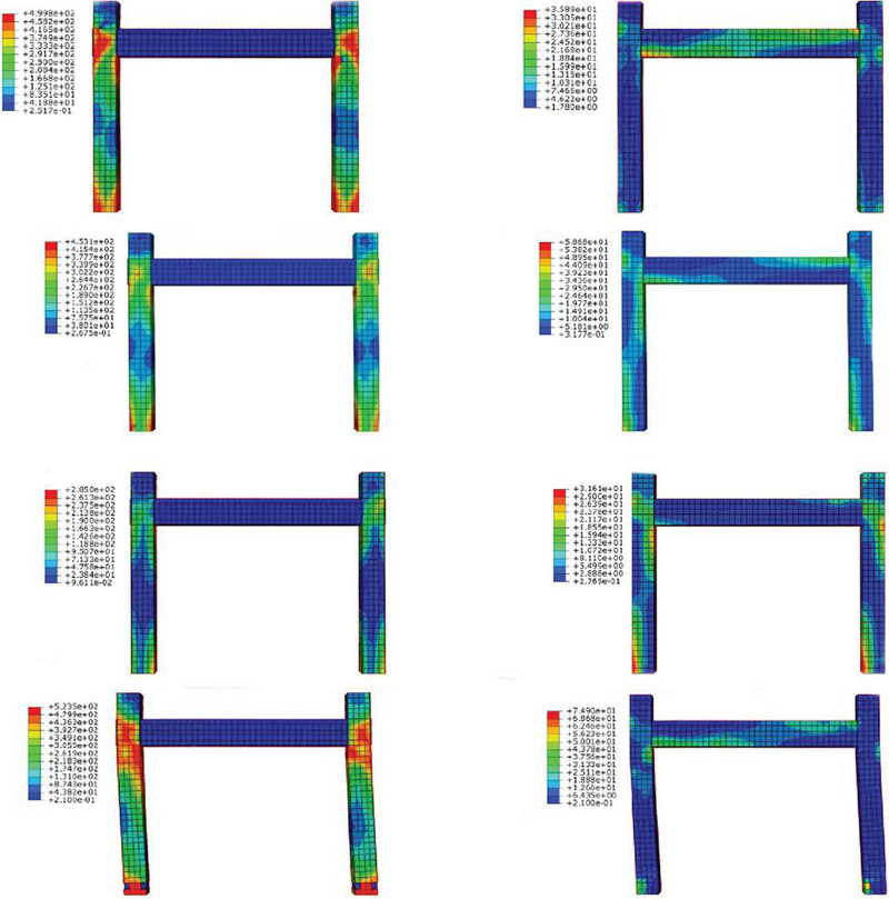
Figure 8 Structural stress distribution diagram.
As shown in Figure 8, when the frame structure exceeds the yield point, the stress concentration effect is significantly reflected in the key areas of the bilateral concrete columns and the ends of the concrete beams. The stress response of the column stems from a dual mechanism: the compressive zone at the top of the column caused by axial loads and the alternating tensile and compressive stress fields generated by horizontal seismic actions. The stress concentration at the beam ends is attributed to the moment concentration effect formed by the transfer of seismic energy and the dynamic amplification effect of the structure. After entering the plastic development stage, the concrete column is the first to experience cumulative damage, with an initial plastic hinge zone formed at the bottom of the column accompanied by stiffness degradation. The overall structural stress level shows a brief decline. As the hysteresis cycle continues, the stress redistribution causes some elements of the double-sided steel tube column to reach the material damage threshold. The number of locally failed elements increases, and the plastic hinge zone at the bottom of the column gradually expands along the column height direction. Eventually, a structured failure mode is formed until the loading is terminated.
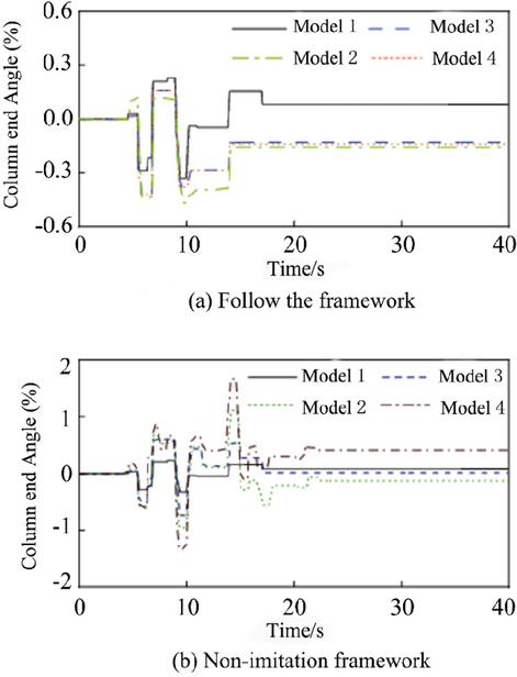
Figure 9 Ductility diagram of the bottom column of the frame structure.
Figure 9 compares the ductility requirements of the base columns of two types of frame structures under rare seismic conditions. Research shows that although the cast-in-place imitation frame can delay the formation timing of column hinges, under the action of high-intensity earthquakes, the ductility requirement of its column body is still significantly higher than that of the cast-in-place frame. In the non-simulated casting frame system, the damage of the Model 4 column is the most severe, manifested as a sharp increase in the corner response. The failure mechanism can be attributed to the weak energy dissipation capacity of the nodes, which forces the seismic input energy to be dissipated through the plastic deformation of the columns. This energy transfer path will aggravate the damage of key load-bearing components and significantly restrict the functional recoverability of the structure after an earthquake.
5 Conclusion
This paper takes the prefabricated multilayer structural framework of a specific manufacturing facility as the research object and studies the seismic mechanical characteristics of multilayer frame structures in prefabricated buildings. The following conclusions are drawn:
(1) By loading the same reciprocating load on the models of in-situ framed structures and prefabricated frame structures under the same conditions, the initial seismic resistance of the two structures is relatively close and can withstand similar loads. However, under larger loads, the rate of decrease in the bearing capacity of prefabricated frame structures will accelerate. Under ultimate loads or large deformations, the ultimate stiffness characteristics of prefabricated frame structures and cast-in-place frame structures exhibit comparable performance, reflecting their similar performance under extreme load conditions.
(2) Under the same seismic conditions, the impact of varying concrete strengths, axial compression ratios, longitudinal steel reinforcement strengths, and beam longitudinal steel reinforcement ratios on the structural response to seismic activity are as follows: two different strength grades of concrete show similar trends in bearing capacity and deformation capacity, pertaining to the maximum story drift observed in Model 1 frame reduced by 12.72% compared to Model 2. Based on the comparative analysis of the range of changes in bearing capacity, it is determined that the longitudinal reinforcement ratio is the most influential factor, followed by the strength grade of the concrete, while the strength of the longitudinal steel bars has a relatively small impact. Compared with Model 1, the maximum inter-story displacement of Model 3 framework has been reduced by 8.33%. This reduction indicates a lower risk of excessive deformation of the structure under seismic loads, which is a positive indicator of structural performance. The yield strength of longitudinal steel bars increases, and the structure has higher bearing capacity, initial stiffness, and greater yield displacement. It has stronger adaptability when plastic deformation occurs. The maximum story drift observed in Model 4 of the structural frame is 13.6% greater than that recorded in Model 1. The bearing capacity of the Model 5 structure with a diminished reinforcement ratio is lower, and as the load increases, the rate of decrease in bearing capacity is faster than that of Model 1. The maximum story drift of the Model 1 structural framework exhibits a reduction of 9.64% in comparison to Model 5.
Funding
This project is sponsored by 2025 Jiaozuo City Science and Technology Plan Project. Research on the Application of Assembly Building Construction Safety Management Integrating Digital Twin (Grant No. 2025430002); Research on Influencing Factors of Construction Cost and Optimization of Process Management for Prefabricated Buildings in Jiaozuo City (Grant No. 2025430003).
References
[1] P Zakian and A Kaveh. (2023). Seismic design optimization of engineering structures: a comprehensive review. Acta Mechanica 234(4), 1305–1330.
[2] E P Popov, C E Grigorian and T S Yang. (1995). Developments in seismic structural analysis and design. Engineering Structures 17(3), 187–197.
[3] Y Fan, J Song, X Zhou and H Liu. (2024). Seismic performance evaluation of a frame system strengthened with external self-centering components. Buildings 14(11), 3666.
[4] Y D Aktaş and A Türer. (2016). Seismic performance evaluation of traditional timber Hımış frames: Capacity spectrum method based assessment. Bulletin of Earthquake Engineering 14, 3175–3194.
[5] A Chourasia, S Singhal and Manivannan. (2023). Prefabricated volumetric modular construction: A review on current systems, challenges, and future prospects. Practice Periodical on Structural Design and Construction 28(1), 03122009.
[6] T Gunawardena, T Ngo and P Mendis. (2016). Behaviour of multi-storey prefabricated modular buildings under seismic loads. Earthquakes and Structures 11(6), 1061–1076.
[7] W Ferdous, Y Bai, T D Ngo, A Manalo and P Mendis. (2019). New advancements, challenges and opportunities of multi-storey modular buildings–A state-of-the-art review. Engineering Structures 183, 883–893.
[8] J Dong, Y Bai, Y Liu, X Cong and C Shen. (2024). Seismic damage assessment of new type prefabricated concrete frame joints. Journal of Constructional Steel Research 215, 108553.
[9] C J Zhong, R Q Feng, Z Hui and H Y Li. (2024). Experimental, numerical simulation and design methodology of axial compression performance of combined steel columns for modular buildings. Journal of Building Engineering 98, 111439.
[10] G Zhang, Z Wang, W Ma, Z Wang, L Li, Y Zhou, Y Li and Y Suo. (2025). Experimental study on seismic performance of vertical connection nodes of prefabricated concrete channel. Buildings 15(10), 1581.
[11] Q Zheng, S Chen and W Lin. (2024). Numerical study on seismic performance of a new prefabricated reinforced concrete structural system integrated with recoverable energy-dissipating RC walls. Buildings 14(10), 3243.
[12] Z Zhu, F Wu and J Hao. (2023). Mechanical behavior of a novel precast concrete beam–column joint using the mortise–tenon connection. Sustainability 15(19), 14586.
[13] B Zhao, D Wu and H Zhu. (2022). New modular precast composite shear wall structural system and experimental study on its seismic performance. Engineering Structures 264, 114381.
[14] X Hu, W Xue and Y Lv. (2023). Experimental studies on structural performance of precast concrete shear walls with innovative UHPC-based connections. Journal of Building Engineering 73, 106748.
[15] R Chang, N Zhang and Q Gu. (2023). A review on mechanical and structural performances of precast concrete buildings. Buildings 13(7), 1575.
[16] Q Zhou, Y Liu and Y Li. (2022). Load transfer mechanism of precast concrete piers with demountable connections. Engineering Structures 261, 114287.
[17] S Mokhtari and M Hassan. (2024). Performance of bond between old and new concrete layers: The effective factors, durability and measurement tests – a review. Infrastructures 9(10), 171.
[18] H Liu, H Zou, J Zhang, J Zhang, Y Tang, J Zhang, Y Guo and J Xiao. (2024). Interface bonding properties of new and old concrete: A review. Frontiers in Materials 11, 1389785.
[19] S S Surya and R Sajeeb. (2021). A review on the plastic hinge characteristics of beam-column joints in RC moment resisting frames. AIJR Proceedings 52–61.
[20] Y Xiao, M Yu and W Liu. (2024). Finite element analysis of prefabricated semi-rigid concrete beam–column joint with steel connections. Applied Sciences 14(12), 5070.
[21] J H Sørensen, L C Hoang, J F Olesen and G Fischer. (2017). Testing and modeling dowel and catenary action in rebars crossing shear joints in RC. Engineering Structures 145, 234–245.
[22] T Yin, Z Wang, K Zheng and S Lu. (2022). A new method for design of the semi-rigid steel frame—the integration of joint inverse design and structural design. Buildings 12(7), 938.
[23] R P Dhakal and J Su. (2018). Design of transverse reinforcement to avoid premature buckling of main bars. Earthquake Engineering and Structural Dynamics 47(1), 147–168.
[24] F Mitjana, S Cafieri, F Bugarin, C Gogu and F Castanie. (2019). Optimization of structures under buckling constraints using frame elements. Engineering Optimization 51(1), 140–159.
[25] M Ramirez and G Araya. (2025). Stability analysis of unsteady laminar boundary layers subject to streamwise pressure gradient. Fluids 10(4), 100.
[26] A N T Ihaddoudène, M Saidani and J P Jaspart. (2017). Mechanical model for determining the critical load of plane frames with semi-rigid joints subjected to static loads. Engineering Structures 145, 109–117.
[27] H Çelik and G Ö K H A N ªakar. (2022). Semi-rigid connections in steel structures state-of-the-art report on modelling, analysis and design. Steel and Composite Structures 45(1).
[28] H T Thai and S E Kim. (2015). Second-order distributed plasticity analysis of steel frames with semi-rigid connections. Thin-Walled Structures 94, 120–128.
[29] A Saritas and A Koseoglu. (2015). Distributed inelasticity planar frame element with localized semi-rigid connections for nonlinear analysis of steel structures. International Journal of Mechanical Sciences 96, 216–231.
[30] A A Y Yahia. (2022). Influence of semi-rigid connections on the behavior and design of steel frames. Doctoral dissertation, Omdurman Islamic University.
[31] C G Chiorean. (2017). Second-order flexibility-based model for nonlinear inelastic analysis of 3D semi-rigid steel frameworks. Engineering Structures 136, 547–579.
[32] J W Shi, Q Q Wu, B Li, Y Liu, W H Cao and H T Wang. (2024). Fatigue bond behavior of FRP-to-concrete joints with various bonding adhesives. Engineering Structures 301, 117311.
Biographies

Li Jianwei received his Master of Engineering degree from the Henan Polytechnic University in 2010. He is currently a senior engineer at Henan Polytechnic University. His main research direction is engineering project management.

Zhao Yongquan received his Master of Engineering degree from Chongqing Jiaotong University in 2017. He is currently an engineer at Henan Polytechnic University. His main research direction is engineering project management.

Niu Haoshuang received his Ph.D. in Engineering from Chang’an University in 2022. He is currently a master’s student in the School of Civil Engineering at Henan Polytechnic University. His main research direction is intelligent monitoring and early warning of tunnel disasters and engineering project management.
European Journal of Computational Mechanics, Vol. 34_3&4, 195–216
doi: 10.13052/ejcm2642-2085.34341
© 2026 River Publishers