A Plasticity-Based Constitutive Framework for Multi-Scale Modeling of Mechanical Degradation in PEM Fuel Cell Membranes
Jaka Dujc
Faculty of Civil and Geodetic Engineering, University of Ljubljana, Slovenia
E-mail: jdujc@fgg.uni-lj.si
Received 03 September 2025; Accepted 12 November 2025
Abstract
The long-term durability of polymer electrolyte membranes (PEMs) remains one of the key barriers to the widespread deployment of fuel cells. This work presents a plasticity-based constitutive framework for predicting membrane degradation under cyclic hydration and thermal loading. The model combines hydration- and temperature-dependent elasticity, swelling, and plastic strains with a pinhole growth law that is activated only when both mechanical plasticity and chemical degradation are present. A binary fluoride release rate (FRR) switch is introduced to couple chemical activity with defect growth in a computationally efficient manner.
Simulation results reproduce key experimental and modeling trends from the literature. Larger hydration amplitudes accelerate void growth and plastic strain accumulation, while thermal swings increase hydrostatic stresses and material softening, thereby enhancing defect evolution. The framework thus provides a physically consistent rationale for the coupled influence of hydration variability, thermal cycling, and chemical degradation on membrane lifetime.
While simplified in geometry and chemistry, the present approach captures the irreversible nature of plastic deformation and remains tractable for long-term cycling studies. It provides a robust basis for future extensions toward 2D/3D analyses and for integration into multi-physics durability assessments of PEM fuel cells.
Keywords: PEMFC, mechanical degradation, plasticity, swelling strain, numerical modeling.
1 Introduction
Proton exchange membrane fuel cells (PEMFCs) are widely considered a promising energy conversion technology for sustainable power generation due to their high efficiency and zero direct emissions. Despite their potential, the limited lifetime of PEMFCs remains a critical barrier to large-scale deployment. In particular, the durability of the polymer electrolyte membrane plays a central role, as membrane failure directly leads to cell shutdown.
A wide range of chemical and mechanical degradation mechanisms in polymer membranes have been reported in the literature, as reviewed comprehensively by Kusoglu and Weber [1]. Among these, mechanical failure of the membrane under cyclic operating conditions is of particular concern. Variations in humidity and temperature lead to inhomogeneous swelling and thermal strains, which generate cyclic stresses and eventually result in fatigue, plastic deformation, and the formation of pinholes. Pinhole formation is a typical example of a localized failure process that critically undermines membrane integrity.
Several modeling approaches have been proposed to describe the mechanical response of PEMFC membranes under cyclic operating conditions. Early work by Kusoglu et al. introduced a linear elasto-plastic constitutive framework for PFSA membranes, emphasizing the role of plastic deformation under hydration cycles [2]. Building on this, Kusoglu et al. highlighted the importance of swelling anisotropy in driving fatigue stresses, demonstrating how humidity cycling accelerates membrane degradation [3]. Tang et al. provided detailed experimental data on the humidity- and temperature-dependence of Nafion’s mechanical properties, offering key input for subsequent constitutive models [4]. Later, Kusoglu and Weber combined experimental measurements and simulations to examine stress redistribution during hydration–dehydration cycles, confirming that in-plane tensile stresses dominate and are critical for pinhole initiation [5]. Ehlinger et al. further advanced the modeling of fatigue-driven degradation by linking microstructural evolution with continuum-level constitutive descriptions [6]. More recently, Hyoung et al. explored swelling-induced stresses under realistic operating profiles, providing new insights into localized damage mechanisms [7]. Finally, Mehrtash et al. developed a comprehensive visco-elasto-plastic framework that incorporates hygro-thermal loading, clamping effects, and plasticity, showing that local water content and load transients critically determine the onset of failure [8].
In the broader field of computational mechanics, several advanced techniques have been developed to describe localized failure phenomena. Methods such as the extended finite element method (XFEM) [9] and strong discontinuity or embedded-discontinuity FEM approaches [10, 11] have proven effective in simulating crack initiation and growth. Similarly, phase-field approaches are increasingly popular for capturing the evolution of localized defects [12, 13]. These methods, however, are computationally demanding and therefore less suitable for fast predictive tools that need to be integrated into multi-physics, multi-scale lifetime models of fuel cells.
The present work develops a plasticity-based constitutive framework tailored for PEMFC membranes, aiming to balance physical realism with computational robustness. The model captures the interaction of temperature, hydration, and plastic deformation. Its novelty lies in enabling direct coupling with chemical degradation models: the initiation of pinholes is linked to the chemical degradation response, allowing for a more realistic description of membrane lifetime. In this way, the framework provides a fast and reliable building block that can be integrated into broader multi-scale tools for fuel cell durability assessment, such as the coupled performance–degradation modelling architectures recently outlined by Scoletta and Schumacher [14] and Schaerer and Schumacher [15].
The paper is structured as follows. Section 2 introduces the model geometry and constitutive framework, including the treatment of swelling, thermal, and plastic strains as well as the pinhole growth law. Section 3 presents the numerical results and compares them with available literature data. Section 4 provides a discussion of the findings and highlights their integration into broader multi-scale durability frameworks. Finally, Section 5 concludes the study with perspectives for future developments.
2 Methodology
This section describes the constitutive framework and numerical implementation of the proposed membrane degradation model. The formulation is based on a decomposition of the total strain into elastic, plastic, swelling, and thermal contributions. The following subsections present the model geometry, constitutive relations, and the numerical implementation used to simulate cyclic loading conditions. For clarity, a complete list of symbols used throughout the paper is provided in Appendix A.

Figure 1 Geometry and boundary conditions of the membrane model. Left: schematic 2D cross-section of the membrane–electrode assembly (MEA), consisting of bipolar plates (BPP), gas diffusion layers (GDL), and the polymer electrolyte membrane (PEM), also referred to as the catalyst coated membrane (CCM). Right: reduced 1D representation of the PEM along the through-plane (thickness) direction, where the in-plane dimensions are omitted and a unit cross-sectional area is assumed. The membrane thickness is denoted by , and the in-plane (cross-sectional) area by . Boundary conditions are applied at the two membrane surfaces: the bottom interface is fixed (), while the top boundary is either subject to a prescribed displacement or, alternatively, to an applied normal stress .
2.1 Model Description and Geometry
In Figure 1, we present the geometry and boundary conditions of the mechanical model. To better illustrate the modeling assumptions, Figure 1 shows both the schematic 2D cross-section of the membrane-electrode assembly (MEA), consisting of bipolar plates (BPP), gas diffusion layers (GDL), and the polymer electrolyte membrane (PEM, sometimes also referred to as the catalyst coated membrane, CCM), and the reduced 1D representation used in this work.
The analysis focuses exclusively on the PEM, while all other components of the MEA are omitted from the mechanical formulation. The PEM is represented by a 1D domain aligned with the membrane thickness , allowing for efficient evaluation of the dominant degradation mechanisms while retaining the essential through-plane stress and strain response. The simplification to a 1D geometry is consistent with prior studies of membrane mechanics and is justified by the large aspect ratio between in-plane dimensions and membrane thickness [6, 16].
Boundary conditions are imposed only at the bottom and top of the membrane. At the bottom boundary, corresponding to the interface with the catalyst layer of one electrode, the displacement is fixed (). At the top boundary, representing the opposite catalyst layer interface, either a prescribed displacement or a clamping pressure is applied. The cross-sectional area of the domain is assumed to be of unit size, .
2.2 Kinematic and Constitutive Framework
The starting point of the formulation is the standard strain–displacement relation. In the reduced 1D formulation, the only non-zero kinematic variable is the through-plane strain
| (1) |
while all in-plane and shear strains are set to zero. Due to symmetry, the stresses in the - and -directions are identical, , even though the corresponding total strains vanish.
Under these assumptions, Hooke’s law simplifies to
| (2) | ||
| (3) |
which are equivalent to relations used in previous membrane models [6, 3, 8]. Although the in-plane strains vanish, the elastic contributions remain non-zero due to the coupling through Poisson’s ratio.
Following common practice in membrane mechanics [3, 6, 7, 5], the total strain tensor is decomposed as
| (4) |
where is the elastic strain, the irreversible plastic strain, the swelling strain due to hydration, and the thermal strain due to temperature variations. This decomposition provides the constitutive basis of the model and is elaborated in the following subsections.
2.3 Elastic Modulus
The Young’s modulus is expressed as a function of the polymer volume fraction , which accounts for the effect of water content [5, 6, 7]:
| (5) |
with
| (6) |
where EW is the equivalent weight, MW the molar mass of water, and the dry-membrane density. The exponent in (5) is a scaling factor that determines the sensitivity of the modulus to hydration. Corrections for temperature and chemical degradation are included following [16], yielding
| (7) |
where is the current temperature, FRR the fluoride release rate, the pristine modulus, and is the degradation constant.
2.4 Thermal Strain
Thermal expansion is modeled using the standard isotropic form [3, 5, 8, 6, 7]:
| (8) |
with coefficient of thermal expansion and reference temperature .
2.5 Swelling Strain
The swelling strain is directly coupled to water uptake and defined by [5, 6, 16]:
| (9) |
where and in-plane isotropy is assumed ().
2.6 Plasticity
Plastic deformation is described using von Mises plasticity with isotropic hardening [3, 5, 8, 6, 7]. In the reduced 1D setting, the von Mises stress simplifies to
| (10) |
and the flow rule is associative,
| (11) |
with deviatoric stress and plastic multiplier . The equivalent plastic strain is accumulated as
| (12) |
The yield strength is parameterized following [5] as
| (13) |
with the dry yield stress, the polymer volume fraction, a scaling exponent, and the hardening parameter.
In summary, the constitutive framework accounts for hydration- and temperature-dependent elasticity, thermo-hygro swelling, and irreversible plastic deformation under cyclic loads. Together, these relations provide the basis for the chemo-mechanical degradation simulations in the following sections.
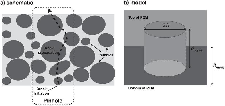
Figure 2 Schematic and model representation of pinhole formation. (a) schematic illustration of pinhole initiation and crack propagation through membrane bubbles. (b) simplified cylindrical pinhole model used in the constitutive framework, defined by the radius and the membrane thickness .
2.7 Pinhole Growth Model
A schematic representation of the physical mechanism of pinhole initiation and the simplified cylindrical model used in this work are shown in Figure 2. Figure 2 illustrates both the physical mechanism of pinhole formation through bubble coalescence and crack propagation, and the simplified cylindrical model adopted in this work. The formation of bubbles is generally attributed to chemical degradation processes that locally weaken the membrane microstructure and lead to gas accumulation.
The evolution of pinhole defects is modeled through a radius growth law originally proposed by Kusoglu and Weber [5]. The rate of pinhole radius growth is expressed as
| (14) |
where is the pinhole radius, is a material growth coefficient, and
| (15) |
is the mean stress, while is the von Mises stress. Equation (14) links the mechanical driving force, represented by the stress state and plastic strain rate , to the defect growth kinetics.
As noted by Lim et al. [7], mechanical loading alone does not produce significant pinhole growth in the absence of concurrent chemical degradation. To reflect this experimental observation, we extend (14) by introducing a threshold condition on the fluoride release rate (FRR), which serves as a measure of chemical degradation activity. The modified relation reads
| (16) |
where the correction factor is defined as
| (17) |
with denoting the critical threshold FRR at which pinhole formation becomes energetically feasible.
This formulation ensures that pinhole nucleation and growth occur only in the presence of both mechanical driving forces and sufficient chemical degradation, thus providing a more physically consistent coupling between the chemical and mechanical degradation pathways.
2.8 Numerical Implementation
The constitutive framework described above was implemented in the finite element environment COMSOL Multiphysics [17]. A one-dimensional structural mechanics model was defined along the membrane thickness direction, with displacement boundary conditions corresponding to those shown in Figure 1. The membrane was discretized with linear Lagrange elements, and quasi-static analyses were carried out under prescribed cyclic hydration and thermal loading.
The constitutive behavior was introduced through user-defined subroutines combining the elastic, plastic, swelling, and thermal strain components. Plasticity was formulated using the built-in von Mises yield criterion with isotropic hardening, while swelling and thermal strains were implemented as additive inelastic contributions following equations (7)–(13). The evolution of the pinhole radius was included by solving the ordinary differential equation (16) in a global ODE node, which was coupled to the stress and equivalent plastic strain fields of the mechanical problem.
A time-dependent solver with adaptive step control was used to integrate the constitutive relations over multiple humidity and temperature cycles.
3 Results
3.1 Loading and Boundary Conditions
All simulations are based on the one-dimensional membrane representation introduced in Section 2, with the through-plane direction aligned along the membrane thickness . Boundary conditions follow Figure 1: the bottom boundary, corresponding to one membrane–electrode interface, is fixed in displacement (), while the top boundary, representing the opposite interface, is traction-free (). No external mechanical pressure is applied in the base case.
The primary time-varying load arises from the membrane water content , which enters the constitutive framework through the swelling strain . In all base case simulations, is cycled with amplitude using a piecewise linear variation in time, representing hydration–dehydration cycling under isothermal conditions (K). This cyclic swelling is the main driver of stress and plasticity in the base case.
In addition, the model is coupled to a chemical degradation law through the FRR. For the base case, a simple linear increase is prescribed,
| (18) |
which activates the chemical contribution in the constitutive framework and enters the pinhole growth law (Section 2.7).
In parametric extensions, further loads are superimposed. For example, in the temperature-swing case presented in Section 3.4, a thermal cycle between and K is imposed concurrently with hydration cycling. This adds thermal strain to the constitutive response and accelerates the overall degradation process.
Table 1 Base case parameters and material constants used in the simulations
| Parameter | Symbol | Value | Unit |
| Membrane thickness | 60 | m | |
| Young’s modulus (dry) | 250 | MPa | |
| Critical FRR threshold | 0 | mol/cm2 | |
| Yield strength (dry) | 7.5 | MPa | |
| Poisson’s ratio | 0.35 | – | |
| Density | 1.97 | g/cm3 | |
| Equivalent weight | 1100 | g/mol | |
| Molar mass of water | 18 | g/mol | |
| Hardening exponent | 0.2 | – | |
| Scaling exponents | , | 2.4, 3.6 | – |
| Thermal expansion coeff. | 1/K | ||
| Clamping pressure | 0 | MPa | |
| Hydration amplitude | 16 | – | |
| Temperature | 300 | K | |
| Reference temperature | 300 | K | |
| Simulation time | 10 | s | |
| Swelling anisotropy factors | , , | – |
3.2 Base Case Simulation
To establish a reference for subsequent parametric studies, we first analyze a base case representing typical membrane operating conditions. The imposed hydration cycling leads to a characteristic evolution of strain, stress, material properties, and pinhole radius.
The material constants and operating parameters adopted for the base case are summarized in Table 1.
Figure 3 shows the strain evolution across hydration cycles. The cyclic hydration loading induces alternating expansion and contraction of the membrane. While the majority of the strain is reversible, a non-negligible plastic component accumulates with each cycle, consistent with earlier observations [3, 5, 8].
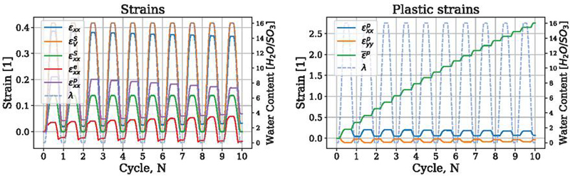
Figure 3 Evolution of strain response during hydration cycles in the base case simulation. Left: Strain decomposition. Right: accumulated plastic strain.
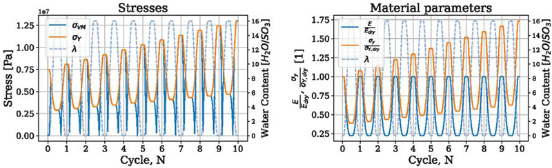
Figure 4 Stress response and material degradation during hydration cycles in the base case simulation. Left: von Mises stress and yield strength. Right: normalized Young’s modulus and yield strength.
The stress and material evolution are summarized in Figure 4. The left panel compares the von Mises stress with the evolving yield strength, showing that cyclic exceedance of the yield surface initiates plastic deformation. The right panel illustrates the concurrent changes in Young’s modulus and yield strength during hydration cycling. A clear softening effect is observed at high hydration levels, reflected in reduced stiffness and strength, while cyclic plasticity contributes to an overall hardening of the material response.
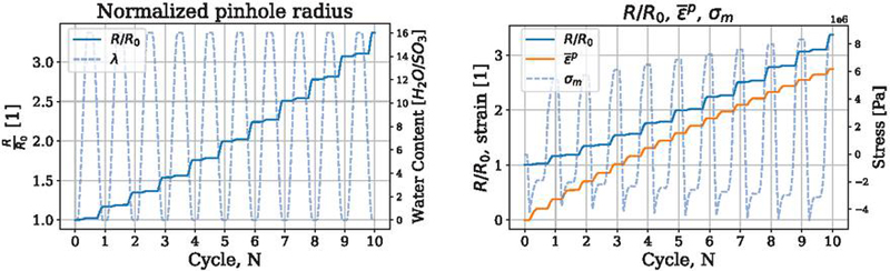
Figure 5 Pinhole evolution in the base case simulation. Left: Normalized pinhole radius during hydration cycles. Right: coupling of pinhole growth with equivalent plastic strain and mean stress.
Finally, Figure 5 presents the evolution of the pinhole radius. The radius grows gradually with cycling and becomes active only when both chemical degradation (via the FRR) and mechanical plasticity are present. In the base case, the critical FRR threshold is set to zero, which means that pinhole growth is permitted from the very beginning of the analysis. The right panel of Figure 5 illustrates the correlation between pinhole growth, equivalent plastic strain, and mean stress, underscoring the strongly coupled nature of the underlying mechanisms.
3.3 Effect of Chemical Degradation Rate and Activation Threshold
To evaluate the sensitivity of the model to the chemical degradation history, we performed additional simulations varying both the temporal evolution of the fluoride release rate and the activation threshold that governs the onset of chemical–mechanical coupling.
Four representative forms of were tested, as summarized in Figure 6 (left). All simulations in this comparison used a constant activation threshold of . Each curve reaches a similar cumulative degradation level after 10 cycles, , but differs in its temporal evolution:
1. Linear: the base case, defined in equation (18).
2. Saturating exponential: rapid early degradation followed by saturation,
| (19) |
3. Delayed superlinear: incubation phase followed by accelerated damage,
| (20) |
4. Two–stage bilinear: regime shift in the chemical degradation rate,
| (21) |
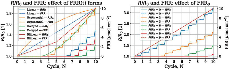
Figure 6 Sensitivity of the coupled model to the chemical degradation history and activation threshold. Left: Influence of different fluoride release rate histories on the normalized pinhole radius . Right: Effect of the activation threshold on for the base–case linear .
In the complementary threshold study (Figure 6, right), was varied as , , , and while maintaining the linear profile from equation (18). Higher threshold levels delay the onset of defect growth and reduce cumulative over the same number of cycles.
Together, these results show that chemical activity primarily influences the timing of pinhole growth rather than its instantaneous rate. Once activated, the mechanical component (, , and ) dominates the growth kinetics.
3.4 Effect of Temperature Swing on Void Growth and Material Response
This subsection considers the case of additional loading through temperature swings. Figure 7 compares the predicted increase in void radius and plastic strain over thermal cycles for the base case and a case with a temperature swing between 300–-380 K (left). The right panel shows the corresponding material behavior. All other parameters remain identical to the base case.
In the left panel, both and increase more rapidly under , highlighting the acceleration of mechanical degradation. The right panel shows that this behavior correlates with pronounced reductions in elastic modulus and yield stress, consistent with the higher hydration and temperature levels reached during cycling. In the thermal swing case, slightly higher yield strength values are observed during the dry portions of the cycles, arising from the accelerated accumulation of plasticity.
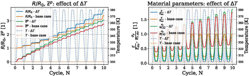
Figure 7 Influence of thermal swing on void growth, plasticity and material parameters. Left: Comparison of and between base case and temperature-swing case. Right: Normalized elastic modulus and yield strength .
Figure 8 contrasts the stress evolution (left) and strain decomposition (right) between the base and temperature-swing cases.
The von Mises and hydrostatic stresses reach higher values under , particularly during rapid cooling. The strain decomposition reveals that swelling and plastic strains dominate the increase in the through-plane strain, while the elastic contribution remains moderate and the direct thermal strain is comparatively small. This indicates that the primary influence of temperature cycling arises from the coupling of material parameters, rather than from thermal expansion and contraction alone.
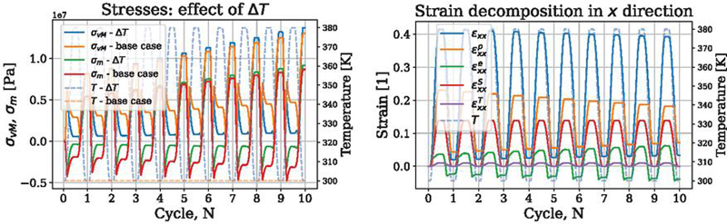
Figure 8 Effect of temperature swing on stresses and strains. Left: Evolution of von Mises stress and hydrostatic stress . Right: Total strain decomposed into plastic, elastic, swelling, and thermal components.
3.5 Effect of Hydration Amplitude on Void Growth and Plasticity
To assess the sensitivity of the model to variations in hydration loading, we next investigate the effect of hydration amplitude on void growth and plastic deformation.
Figure 9 contrasts the predicted increase in void radius over RH cycles with digitized data from [5] (left), and shows the accumulated equivalent plastic strain for the present model (right). For ease of comparison, the values at are summarized in Table 2.
On the void-growth side (Figure 9 left), the present simulations show a monotonic -dependence, and the intermediate case falls between the literature responses at and . The plasticity panel (Figure 9 right) links this behavior directly to inelastic deformation: larger produces greater over ten cycles.
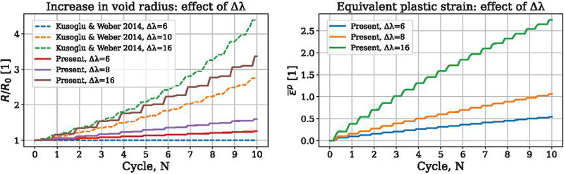
Figure 9 Influence of hydration amplitude on void growth and plasticity. Left: vs. cycles for the present model (; solid) compared with [5] (; dashed). Right: Accumulated equivalent plastic strain for the present model.
Table 2 Key values at extracted from Figure 9. A dash indicates data not reported for in [5]
| Case | ||
| Present | 1.27 | 0.54 |
| Present | 1.61 | 1.06 |
| Present | 3.37 | 2.75 |
| [5] | 1.00 | – |
| [5] | 2.75 | – |
| [5] | 4.39 | – |
4 Discussion
The results presented above confirm that pinhole evolution in PEM membranes under cyclic hydration is governed by a tightly coupled set of mechanisms. In the present framework, the growth law (equation (16)) depends explicitly on four factors: (i) mean stress , (ii) von Mises stress , (iii) equivalent plastic strain rate , and (iv) chemical switch factor based on FRR. This formulation reflects experimental findings that mechanical loading alone is insufficient to activate pinhole growth [7], and that a combination of plastic deformation and chemical degradation is required to initiate stable defect enlargement.
From a mechanistic perspective, positive during deswelling provides the tensile driving force for crack-like void enlargement, while together with govern the onset and rate of plastic flow. The equivalent plastic strain also serves as an irreversible measure of material degradation. The FRR-based switch ensures that mechanical loading translates into defect growth only once sufficient chemical degradation has weakened the microstructure. Taken together, this fourfold dependency provides a physically consistent rationale for the observed sensitivity of to the hydration amplitude .
The temperature-swing simulations further highlight the importance of thermo-mechanical coupling. As shown in Figures 7 and 8, introducing a cyclic temperature variation between 300–380 K significantly accelerates both void growth and plastic deformation. This response is directly linked to the evolution of material parameters: higher peak hydration and temperature levels induce more severe decrease of the elastic modulus and yield strength. Consequently, the membrane undergoes earlier yielding and accumulates more plastic strain per cycle. It should be noted that in real PEMFC operation, temperature variations are often coupled with changes in local water content due to evaporation or flooding phenomena. Such thermo-hygroscopic interactions are not explicitly captured in the present one-dimensional model, which isolates the mechanical contribution of temperature cycling. This simplification is justified given the study’s focus on chemo–mechanical coupling rather than full water transport modeling.
Additionally, the stress profiles reveal higher tensile hydrostatic states under temperature swings, particularly during cooling/drying phases. These stress fluctuations amplify the driving forces for plasticity and pinhole growth. The decomposition of strain in the through-plane () direction shows that swelling and plastic components dominate the total strain, while the elastic contribution remains moderate and the direct thermal strain is comparatively small. These findings are consistent with prior experimental and modeling studies, which have shown that combined humidity and temperature cycling accelerates mechanical degradation and promotes void growth in PEM membranes [8, 7].
Taken together, the results emphasize that both hydration amplitude and temperature variability must be included in any realistic durability assessment. Neglecting temperature effects would significantly underestimate the rate of mechanical degradation.
The additional analysis in Section 3.3 clarifies the sensitivity of the coupled model to the chemical degradation history. Varying the fluoride release rate demonstrated that the chemical pathway primarily governs the activation timing of pinhole growth, while its instantaneous rate remains controlled by the mechanical variables . Among the tested forms, early-peaking histories such as exponential produced faster activation and higher cumulative , whereas delayed or multi-stage evolutions postponed defect initiation. Similarly, the threshold parameter effectively shifts the onset of chemical–mechanical coupling: higher values delay growth activation and reduce total degradation over a fixed number of cycles. These findings confirm that the inclusion of the term provides a realistic and physically motivated control mechanism that prevents unphysical early damage and offers a direct means to calibrate the model against experimental fluoride emission data.
4.1 Comparison with Existing Models
The proposed constitutive framework bridges the gap between purely mechanical growth laws [5] and recent chemo-mechanical formulations [8, 7]. Unlike purely elastic or phenomenological growth formulations, the plasticity-based approach captures the irreversible nature of deformation and directly links fatigue-like enlargement of voids to the yield condition. Compared with Ehlinger et al. [6], our formulation introduces a simplified but robust switch factor for chemistry (FRR), which makes it computationally efficient for long-term cycling studies. The present predictions reproduce literature trends, while quantitative deviations highlight the role of parameter calibration (e.g., hydration-dependent yield strength, swelling anisotropy) and dimensional reduction (1D vs. 2D/0D formulations).
4.2 Integration into Multi-Physics Frameworks
A key novelty of the present approach lies in its modularity. The FRR switch establishes a direct interface with chemical degradation models, such as those describing peroxide radical attack and fluoride release. In this way, the mechanical kernel can be coupled with higher-level frameworks that integrate catalyst degradation and performance decay. In particular, the works of Scoletta and Schumacher [14] and Schaerer and Schumacher [15] outline a system-level modelling architecture for PEMFCs, in which the present mechanical block can serve as a fast and reliable durability predictor. This coupling opens the path towards comprehensive, multi-scale lifetime assessment tools that combine electrochemical performance, chemical degradation, and structural failure.
4.3 Limitations and Outlook
Despite these advantages, several simplifications remain. The present framework is rate-independent. While this is appropriate given the relatively slow loading cycles considered here, dynamic effects could become relevant under faster transients.
The one-dimensional geometry neglects the heterogeneous boundary conditions imposed by gas diffusion layers, catalyst layers, and flow-field ribs. As a result, it may either underestimate or overestimate local tensile states, depending on the location within the membrane. A more detailed 2D or 3D analysis would enable assessment of these constraint effects and provide a basis for introducing correction factors in reduced-order models.
In addition, the current FRR switch is binary and the threshold level is prescribed rather than calibrated. Determining appropriate values of from experimental data in the literature would improve the physical grounding of the model. Finally, replacing the binary switch with a continuous kinetic law would further enhance quantitative fidelity. These aspects will be addressed in future work, where the model will be extended with more realistic swelling constraints that account for anisotropy in the in-plane directions, enabling the representation of heterogeneous boundary conditions under flow-field ribs and channels, and coupled with a continuous chemo-mechanical law.
5 Conclusion
This study presents a plasticity-based constitutive framework for predicting the mechanical degradation of PEM fuel cell membranes under cyclic hydration and thermal loading. The formulation couples hydration- and temperature-dependent elasticity, swelling, and plasticity with a pinhole growth law that activates only when mechanical and chemical degradation act concurrently. Through the introduction of an FRR-based switching term, the model provides a physically transparent and computationally efficient means of linking mechanical loading with chemical activity.
The simulations reproduced key experimental and modeling trends from the literature. Larger hydration amplitudes accelerated void growth and plastic strain accumulation, while temperature swings amplified hydrostatic stresses and material softening, leading to faster defect evolution. The sensitivity analysis of the chemical degradation rate and activation threshold further showed that chemical activity primarily governs the timing of defect initiation, whereas the subsequent growth rate is dominated by mechanical response. Together, these results confirm that hydration variability, thermal cycling, and progressive chemical degradation jointly control the long-term durability of PEM membranes.
While simplified in geometry and chemistry, the proposed model establishes a consistent basis for studying the interplay between swelling, plasticity, and chemical damage. Future work will focus on quantitative calibration of the chemical activation parameters ( and ) from experimental data and on extending the framework toward continuous chemo–mechanical coupling in higher-dimensional simulations, enabling integration with multi-physics lifetime assessment tools for PEM fuel cells.
Acknowledgments
This work was supported by the Slovenian Research and Innovation Agency through the research programme P2-0210 eConstruction. The author acknowledges the Institute of Computational Physics, ZHAW, Winterthur, Switzerland, as a collaboration partner. Special thanks are extended to Professor Juergen Schumacher for helpful discussions and for referring relevant literature used in this study.
Appendix A. List of Symbols
| Symbol | Description | Unit |
| Cross-sectional area (assumed) | m2 | |
| Pinhole growth coefficient | – | |
| Correction factor for FRR activation | – | |
| Young’s modulus | MPa | |
| Young’s modulus of dry membrane | MPa | |
| Pristine Young’s modulus | MPa | |
| Equivalent weight | g/mol | |
| FRR | Fluoride release rate | mol/cm2 |
| Critical FRR threshold | mol/cm2 | |
| Hardening parameter | – | |
| Degradation constant in modulus law | – | |
| Membrane water content | – | |
| Plastic multiplier / plastic consistency parameter | – | |
| Hydration amplitude | – | |
| Scaling exponent for | – | |
| Molar mass of water | g/mol | |
| Scaling exponent for | – | |
| Clamping pressure | MPa | |
| Current and initial pinhole radius | µm | |
| Dry membrane density | g/cm3 | |
| Normal stress components | MPa | |
| Mean (hydrostatic) stress | MPa | |
| von Mises stress | MPa | |
| Yield strength | MPa | |
| Yield strength of dry membrane | MPa | |
| Final simulation time | s | |
| Temperature | K | |
| Reference temperature | K | |
| Displacement in -direction | m | |
| Prescribed displacement (boundary) | m | |
| Coefficient of thermal expansion | 1/K | |
| Membrane thickness | µm | |
| Total strain tensor | – | |
| Elastic strain | – | |
| Plastic strain | – | |
| Swelling strain | – | |
| Volumetric swelling strain | – | |
| Thermal strain | – | |
| Equivalent plastic strain | – | |
| Equivalent plastic strain rate | 1/s | |
| Poisson’s ratio | – | |
| Polymer volume fraction | – | |
| Swelling anisotropy factors | – |
References
[1] Ahmet Kusoglu and Adam Z. Weber. (2017). New insights into perfluorinated sulfonic-acid ionomers. Chemical Reviews 117(3), 987–1104.
[2] Ahmet Kusoglu, Anette M. Karlsson, Michael H. Santare, Simon Cleghorn, and William B. Johnson. (2006). Mechanical response of fuel cell membranes subjected to a hygro-thermal cycle. Journal of Power Sources 161(2), 987–996.
[3] Ahmet Kusoglu, Anette M. Karlsson, Michael H. Santare, Simon Cleghorn, and William B. Johnson. (2007). Mechanical behavior of fuel cell membranes under humidity cycles and effect of swelling anisotropy on the fatigue stresses. Journal of Power Sources 170(2), 345–358.
[4] Yaliang Tang, Anette M. Karlsson, Michael H. Santare, Michael Gilbert, Simon Cleghorn, and William B. Johnson. (2006). An experimental investigation of humidity and temperature effects on the mechanical properties of perfluorosulfonic acid membrane. Materials Science and Engineering: A 425(1–2), 297–304.
[5] Ahmet Kusoglu and Adam Z. Weber. (2014). A mechanistic model for pinhole growth in fuel-cell membranes during cyclic loads. Journal of The Electrochemical Society 161(8), E3311.
[6] Victoria M. Ehlinger, Ahmet Kusoglu, and Adam Z. Weber. (2019). Modeling coupled durability and performance in polymer-electrolyte fuel cells: Membrane effects. Journal of The Electrochemical Society 166(14), F1259–F1271.
[7] Hyoung Jun Lim, Geonwoo Kim, and Gun Jin Yun. (2023). Durability and performance analysis of polymer electrolyte membranes for hydrogen fuel cells by a coupled chemo-mechanical constitutive model and experimental validation. ACS Applied Materials & Interfaces 15(20), 24257–24270.
[8] Mehdi Mehrtash, Ilker Tari, and Serhat Yesilyurt. (2018). Numerical modeling of visco-elasto-plastic hygro-thermal stresses and the effects of operating conditions on the mechanical degradation of PEFC membranes. Journal of Power Sources 396, 164–174.
[9] Himanshu Pathak, Akhilendra Singh, and Indra Vir Singh. (2013). Fatigue crack growth simulations of bi-material interfacial cracks under thermo-elastic loading by extended finite element method. European Journal of Computational Mechanics/Revue Européenne de Mécanique Numérique 22(1), 79–104.
[10] Jaka Dujc and Boštjan Brank. (2022). Modeling fracture in elasto-plastic solids by embedded-discontinuity stress-hybrid finite element formulation. Mechanics of Advanced Materials and Structures 29(5), 677–693.
[11] Virginie Bonnaillie-Noël, Delphine Brancherie, Marc Dambrine, Sébastien Tordeux, and Grégory Vial. (2010). Effect of micro-defects on structure failure coupling asymptotic analysis and strong discontinuity. European Journal of Computational Mechanics 19(1–3), 165–175.
[12] Kais Ammar, Benoît Appolaire, Georges Cailletaud, and Samuel Forest. (2009). Combining phase field approach and homogenization methods for modelling phase transformation in elastoplastic media. European Journal of Computational Mechanics 18(5–6), 485–523.
[13] Jaka Dujc and Boštjan Brank. (2022). Combining coupled, staggered and uncoupled solution methods for phase-field-based fracture analysis. Mechanics of Advanced Materials and Structures 29(27), 6361–6378.
[14] E. Scoletta and J. O. Schumacher. (2025). A modelling framework for the simulation of coupled performance-degradation phenomena in proton exchange membrane fuel cells. Proceedings of ModVal 2025, Karlsruhe, Germany, March 11–12.
[15] R. P. Schaerer and J. O. Schumacher. (2025). Electrochemical interface model coupling oxygen reduction and degradation reactions in the cathode catalyst layer of a PEMFC. Proceedings of ModVal 2025, Karlsruhe, Germany, March 11–12.
[16] Victoria M. Ehlinger. (2020). Modeling Membrane Degradation in Proton-Exchange-Membrane Fuel Cells. PhD thesis, University of Berkeley.
[17] COMSOL. (2022). http://www.comsol.com.
Biography

Jaka Dujc received his PhD in Civil Engineering from the University of Ljubljana and ENS Cachan in 2010. He is currently an Assistant Professor at the Faculty of Civil and Geodetic Engineering, University of Ljubljana. His research interests include computational mechanics, finite element modeling of failure and plasticity, multi-physics modeling of fuel cells and advanced materials, as well as Building Information Modeling (BIM) and construction information technology.
European Journal of Computational Mechanics, Vol. 34_3&4, 217–240
doi: 10.13052/ejcm2642-2085.34342
© 2026 River Publishers