Improving the Lateral-Resistant Behavior of Steel Plate Shear Walls with CFST Columns Using Two-Layer Flat-Corrugated Plates
Huanqing Jiang1,*, Dongyu Ji2 and Xingpei Wang1
1Hunan Urban Construction College, Xiangtan, Hunan 411100, China
2Henan Institute of Energy and Chemical Technology, Puyang, Henan 457000, China
E-mail: jianghuanqing1985@126.com; xiayuji2016@163.com; wangxingpei1987@126.com
*Corresponding Author
Received 01 January 2026; Accepted 22 June 2026
Abstract
Utilizing flat plates (FPs) in a steel plate shear wall (SPSW) system significantly pinches the hysteresis curves, as these plates are highly susceptible to out-of-plane buckling. In this study, a flat-corrugated plate (FCP) was used in an SPSW system with concrete-filled steel tubes (CFST) columns. In this study, an earlier evaluated traditional flat SPSW with CFST columns was validated in ABAQUS software under cyclic loads. Then, by introducing a two-layer FCP that encompasses both a flat and a trapezoidal corrugated plate, instead of an flat plate (FP), the effects on the hysteresis curve and structural parameters were investigated. The results showed that using an FCP instead of a traditional FP in an SPSW system (FCSPSW) with CFST columns led to a fatter hysteresis curve and, subsequently, a significant improvement in energy dissipation. The maximum resistance of the FCSPSWs with CFST columns was slightly higher than that of the control sample. The results showed that the use of an FCP has a minimal effect on the elastic stiffness.
Keywords: Flat-corrugated SPSW, CFST, hysteresis curve, resistance, energy dissipation.
1 Introduction
The steel plate shear wall (SPSW) was developed as an attractive lateral load-carrying system in the 1970s due to its remarkable advantages, like high strength, stiffness, ductility, and significant energy dissipation capacity [1–4]. This system, which was used in the structures of Nippon Steel and the Ashiyahama residential building complex, showed acceptable performance during the Kobe earthquake [5]. The conventional SPSW, which uses a flat plate (FP) as an infill element, has significant shortcomings. Because the maximum resistance in such a system is activated in the post-buckling stage, with the formation of tensile fields [6], this subsequently results in the occurrence of large forces on the vertical border elements [7, 8]. In addition, the out-of-plane buckling capacity of FPs is low, and the pinching phenomenon also occurs in their hysteresis curve. To overcome these challenges, a corrugated plate (CP) is a suitable solution. Because CPs have higher out-of-plane and in-plane stiffness than FPs [9, 10], it leads to improved buckling behavior of SPSWs.
To date, various laboratory studies have been conducted on the lateral resistance behavior of corrugated SPSWs (CSPSWs), demonstrating their excellent ability to withstand lateral loads in terms of stiffness, strength, and energy absorption capacity [11–16]. Comparative investigations have indicated that flat SPSWs (FSPSWs) show lower energy absorption and initial stiffness compared to CSPSWs. However, they exhibit a higher load-bearing capacity [17, 18]. Therefore, a wall made of CPs, despite improving some of the properties of SPSWs, shows lower resistance than walls made of FPs, which is a great defect. Additionally, since CPs are produced through a cold rolling process, they have a limited thickness of 8 mm [19], which may limit their use in the lower floors of high-rise structures that are exposed to high shear forces. Therefore, a concept has recently been developed that proposes using FP and CP in combination. This proposal aims to utilize the capacity of FPs and CPs by using them simultaneously. In this way, the CP and FPs act as relative stiffeners and support for each other, creating a successful system. Walls made with FPs and CPs, known as flat-corrugated SPSWs (FCSPSWs), are implemented in various designs. In this field, a four-layer flat-corrugated plate (FCP) composed of double-corrugated plates surrounded by FPs was proposed by Broujerdian et al. [20], indicating the better lateral performance of conventional SPSWs, ordinary CSPSWs, and double CSPSWs (DCSPSWs). Nayel et al. [21] and Abbaszadeh et al. [22] also studied the performance of four-layer SPSWs under lateral loading. Dou et al. [23] tested three-layer FCSPSWs composed of middle CPs surrounded by FPs. The results revealed that this model overcomes the shortcomings of conventional SPSWs and CSPSWs.
In addition to steel boundary elements, concrete-filled steel tube (CFST) columns have been employed as vertical boundary elements in SPSWs. Because a CFST frame has benefits such as high strength, stiffness, and ductility [24–26], it can be used as an anchorage for SPSW to utilize the efficiency of infill plates [27]. Tan et al. [28] experimentally investigated the cyclic performance of SPSWs with CFST columns stiffened with cold-formed steels. They found that using cold-formed steels as stiffeners has improved the energy dissipation capacity and lateral load-bearing. Wang and Xie [29] investigated the experimental performance of thin SPSWs with CFST columns stiffened with cross-stiffeners. They observed that stiffening the infill plate has improved the lateral performance. Qiao et al. [30] investigated the seismic performance of SPSW systems with CFST columns and found that the proposed system shows stable hysteretic curves and high energy dissipation capacity. Liao et al. [31] investigated the lateral behavior of the DCSPSWs with CFST columns. The outcomes showed that the studied models have demonstrated high strength, stiffness, and energy dissipation capacity. Hu et al. [32] investigated the structural behavior of beam-connected SPSW with CFST columns. Results indicated that the proposed systems have effectively improved the lateral load-bearing capacity and stiffness compared to the CFST frame. Wang et al. [33] investigated the performance of beam-connected SPSWs with buckling-restrained configuration under cyclic loading. The results demonstrated that experimental specimens exhibited satisfactory lateral resistance and stiffness, confirming that this structural system represents a reliable SPSW configuration.
Despite the demonstrated potential of FCP configurations in enhancing seismic performance, previous studies have predominantly focused on conventional steel boundary frames, leaving the cyclic behavior of FCSPSWs integrated with CFST columns largely unexplored. To address this gap, the current paper introduces a novel two-layer FCPs as infill elements within a CFST column frame. This research is imperative to evaluate whether this streamlined configuration can simultaneously improve energy dissipation and lateral resistance while maintaining elastic stiffness, thereby offering an efficient and practical solution for seismic-resistant design.
2 Study Method
The current paper considers a previously tested a SPSW surrounded by steel beams and CFST columns, as shown in Figure 1. This specimen, labeled SP1, is adopted from [28]. As shown, this specimen has one bay and two stories. In every story, a flat steel plate with a height and width of 1100 mm and a plate thickness of 2.67 mm has been used. A square CFST with a section of has been used for frame columns. HN3001506.59 is used for the top and bottom beams. And is used for the middle beam. Table 1 displays the mechanical attributes of the steel elements. E, , and denotes the Young’s modulus, yield strength, and ultimate strength, respectively.
Table 1 The mechanical attributes of the steel elements [28]
| Steel Specifications | Thickness (mm) | (MPa) | (MPa) | E (GPa%) |
| Infill plate | 312 | 427 | 218 | |
| Square tube of | 300 | 445 | 220 | |
| Square tube of | 285 | 400 | 241 | |
| Flange of HN3001506.59 | 275 | 408 | 210 | |
| Web of HN3001506.59 | 242 | 370 | 211 | |
| Flange of HN200105.58 | 275 | 419 | 220 | |
| Web of HN | 270 | 424 | 210 |
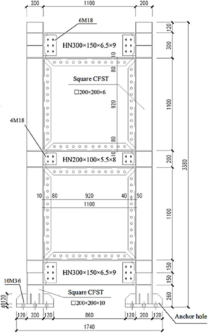
Figure 1 Geometric properties of the SP1 specimen [28].
This paper presents the usage of FCPs in place of conventional FPs. The goal of this study is to determine the effectiveness of the usage of the FCPs as compared to conventional FPs in an SPSW system with CFST columns. Here, the FCP is a combination of an FP and a trapezoidal CP joined together by screws. Since the thickness of the FP in the primary study was 2.67 mm, the thickness of each of the FP and CP will be half of the aforementioned thickness, i.e., 1.335 mm. In this study, trapezoidal CPs have been used. It is worth noting that several CP geometries adapted from other studies have been considered for this work, whose geometric characteristics are shown in Figure 2. The two-layer FCPs, as mentioned earlier, comprise a single FP and CP. These plates are connected through high-strength bolts. In Figure 3, the properties of the two-layer FCPs are shown. As seen, the bolt spacing is h/4 [34].
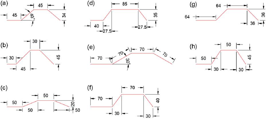
Figure 2 Geometric characteristics of the CPs: (a) [23], (b) and (c) [18], (d) [35], (e) [36], (f) [37], (g) [38], (h) [39].
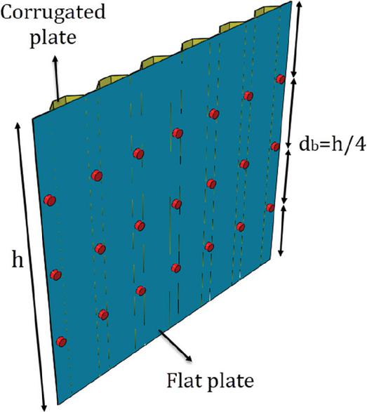
Figure 3 Two-layer FCPs’ properties.
2.1 Finite Element Model
Different models for the study have been designed using a finite element model (FEM) in ABAQUS in this paper. The concrete damaged plasticity (CDP) scheme was used in ABAQUS. The Poisson’s ratio and elastic modulus of concrete were 0.2 and [40], respectively. In this study, a concrete stress-strain model was used for core concrete, considering the effect of confinement inside a square steel tube presented by Tan et al. [41]. The parameters of the CDP model for core concrete were adopted from [42]. The dilation angle was fixed at 30∘, while the flow potential eccentricity (ef) was set to 0.1. The model further adopted a value of 1.16 for the ratio of the second stress invariant on the tensile to that on the compressive meridian (Kc), and the ratio of 2/3 was considered to the initial equiaxial compressive yield stress to the initial uniaxial compressive yield stress (fb0/fc′).
To model steel materials, an elastoplastic material property with a bilinear relationship was used. The hardening modulus is set to be E/100 [23]. In addition, to model the plastic response of the steel members, the ABAQUS model utilizes both the kinematic hardening hypothesis and the von Mises yield criterion [20, 23]. The paper describes how the steel members were simulated utilizing the shell element (S4R). C3D8R element was used to model the core concrete. The average 28-day concrete compressive strength was 33 MPa. A tie constraint was used to connect infill steel plates to boundary members [28]. To simulate the interfacial behavior between the steel tube and the infilled concrete, the normal interaction was defined using a hard-contact formulation, while the tangential behavior was governed by a penalty friction model with a coefficient of 0.6 [29]. To define the contact between FP and CP, connecting bolts were not modeled directly, and the translational degree of freedoms of the bolt location of the plates was coupled in the ABAQUS software [35, 43–46]. In addition, to account for interaction between the FP and CP in the vicinity of the bolts, the corrugation valleys of the CP and the FP were defined as a “surface-to-surface contact” employing “hard contact” [47] in the normal direction and a “frictionless” interaction in the tangential direction [23, 47, 48]. Figure 4 shows the lateral loading and boundary conditions. The boundary conditions of the FEMs reflect the conditions of the laboratory as per the description in [28]. The cyclic lateral loads are imposed on the reference point RP1 that is connected to the face of the column. To incorporate initial geometric imperfections into the numerical model, the outcomes of the eigenvalue buckling analysis were utilized. Two dominant buckling mode shapes were then chosen and combined through superposition to define the imperfection pattern applied to the specimen. The maximum outward deformation of these initial imperfections was taken as 1/1000 of the height of the infilled steel plate, following the approach in references [28, 49, 50]. In addition, geometric nonlinearity is considered in the analysis.
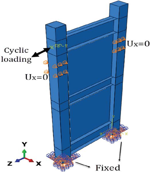
Figure 4 Boundary conditions of the FEMs.
3 Validation
The specimen SP1 was simulated in ABAQUS software under cyclic lateral loading. Figure 5 compares the hysteresis curve of the test and the FEM results. As seen, there is good agreement between test and finite element results. According to [28], the maximum load capacity of the test was 652.8 kN, while the FEM predicted a maximum resistance of 694.5 kN, corresponding to an error of 6.3%. Additionally, the initial stiffness values for the test and the FEM were 36.1 kN/mm and 38.2 kN/mm, respectively, yielding an error of 5.1%.
Figure 6 compares the deformation of the test [28] and FEM corresponds to the maximum lateral displacement. The out-of-plane and von Mises stress distributions are depicted in Figures 6(b) and 6(c), respectively. As seen, the events that occurred on the laboratory specimen were well reproduced in the FEM. All of this indicates the ABAQUS reliability for predicting the cyclic behavior of SPSWs with CFST columns.
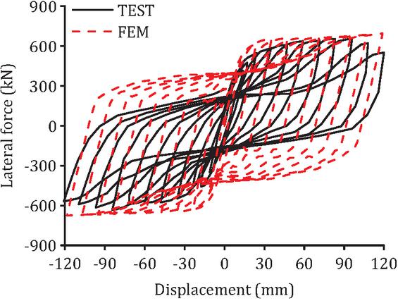
Figure 5 Juxtaposition of the test’s hysteresis curve [28] and FEM.
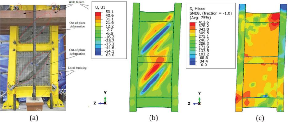
Figure 6 Juxtaposition of deformation of (a) test [28] and FEM, (b) out-of-plane deformation (units: mm), and (c) von Mises stress distribution (units: MPa).
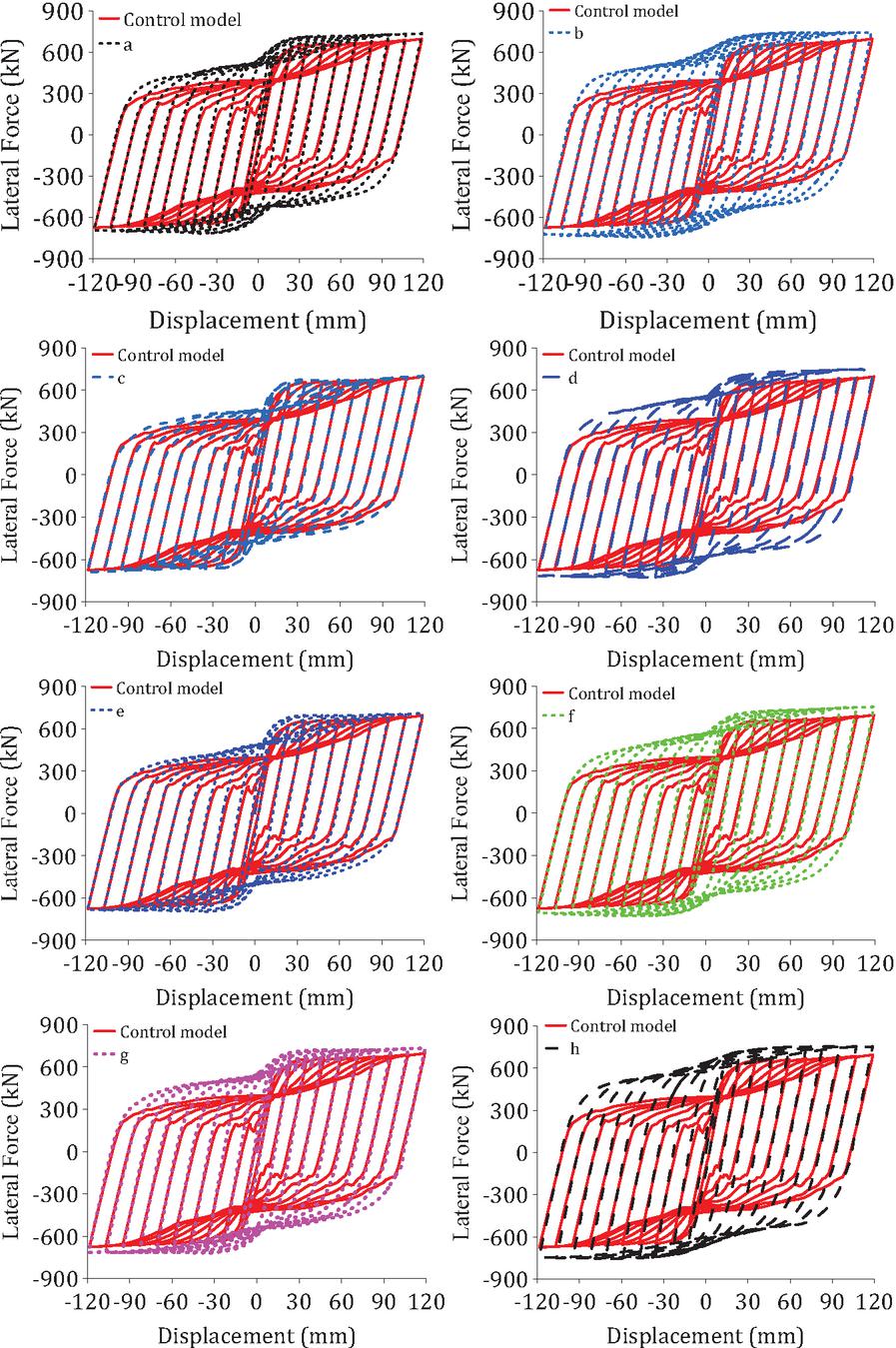
Figure 7 Juxtaposition of the hysteresis curve of SPSWs with the CFST column using FP and FCP.
4 Results and Discussion
4.1 Hysteresis Diagrams
Figure 7 illustrates the hysteresis diagrams of the studied models. The hysteresis curves of FCSPSWs are displayed with those of the control sample in Figure 7. Terms a, b, c, d, e, f, g, h, and i denote the investigated models with FCPs. Letters a, b, c, d, e, f, g, h, and i represent the type of the corrugations, the geometric characteristics of which have been presented in Figure 2. As seen, the hysteresis curves of the FCSPSWs have exhibited a plumper hysteresis curve than the control specimen, indicating the higher capability of the SPSW system with CFST columns using FCPs to dissipate energy compared to the corresponding model with conventional FPs. This figure also shows that the employment of FCPs in SPSWs with CFST columns resulted in a slight increase in the maximum lateral strength. In addition to that, it is evident that the geometric features of the CPs influence the lateral behavior of the SPSW-CFST column systems.
4.2 Structural Parameters
In this section, the structural parameters derived from the hysteresis responses, including maximum resistance, energy dissipation capacity, and elastic stiffness, are discussed. Figure 8 presents a comparison of the maximum resistance of the models under investigation. It can be seen that the maximum resistance of the FCSPSWs with CFST columns is higher than that of the FSPSWs. The difference between them varies from 0.68% to 8.57%. Their mean difference in maximum resistance is 5.8%.
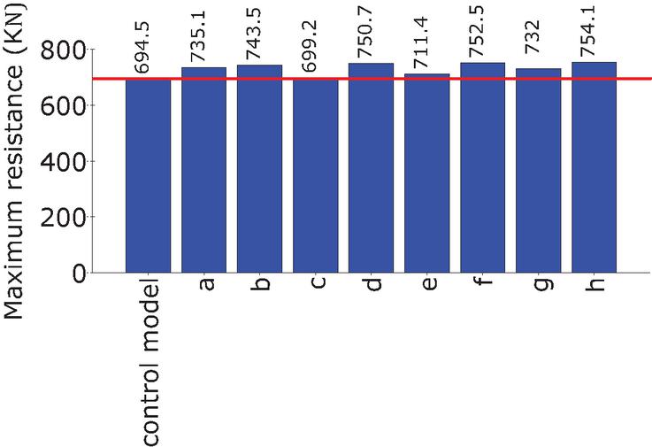
Figure 8 Juxtaposition of the maximum resistance of the reviewed schemes.
Figure 9 shows the cumulative energy dissipation curve of the reviewed schemes. The juxtaposition of energy dissipation of the numerical schemes is shown in Figure 10. As depicted, the FCSPSWs with CFST columns exhibit greater energy dissipation compared to ordinary SPSWs with CFST columns. Their difference in energy dissipation ranges from 11.39% to a maximum of 40.4%. On average, the difference in energy dissipation between FCSPSWs and FSPSWs with CFST columns is 28.4%, indicating that using FCPs instead of FPs in SPSW systems with boundary CFST columns significantly enhances the energy dissipation capacity.
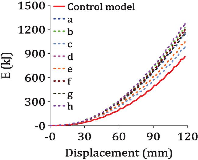
Figure 9 Cumulative energy dissipation curve of the reviewed schemes.
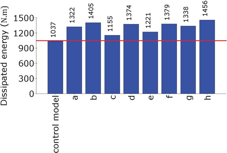
Figure 10 Juxtaposition of energy dissipation of the reviewed schemes.
Figure 11 compares the elastic stiffness of the samples under consideration. It can be seen that the change of the infill plate type hardly affects the elastic stiffness of the numerical models. The results indicates that the elastic stiffness of the FCSPSWs is lower than that of the control model. The difference in elastic stiffness between the FCSPSWs and the control model changes from 0.5% to 3.7%.
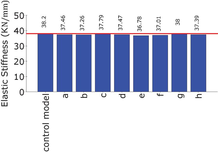
Figure 11 Juxtaposition of elastic stiffness of the reviewed schemes.
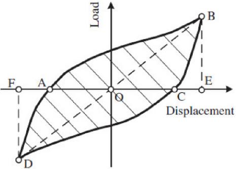
Figure 12 The calculation method of equivalent viscous damping.
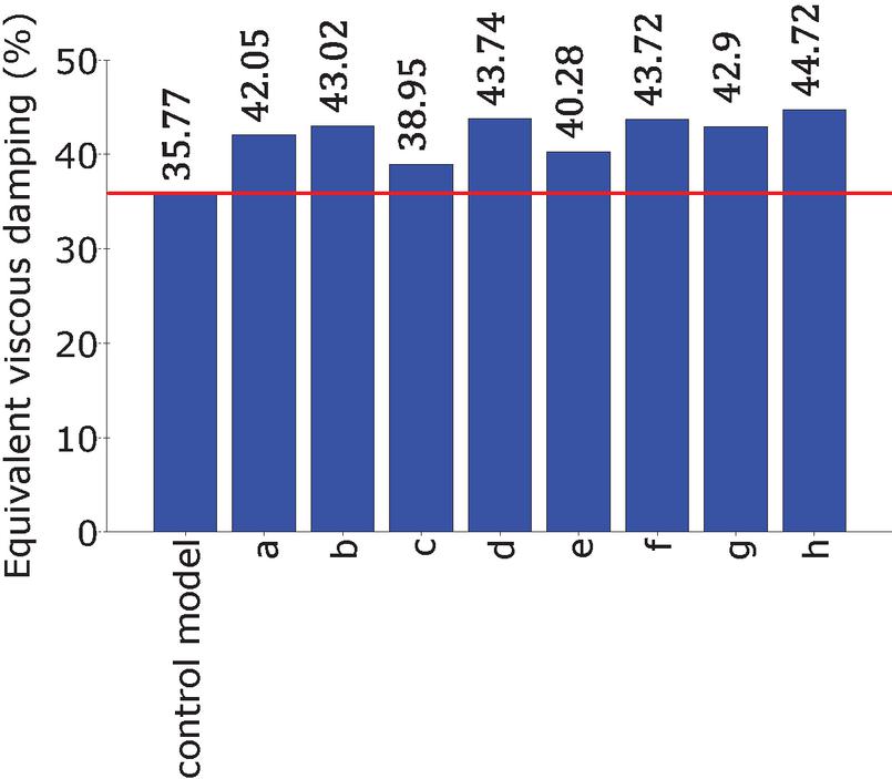
Figure 13 The juxtaposition of the values of the reviewed samples.
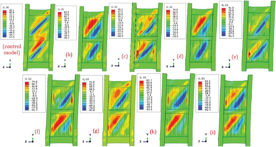
Figure 14 Lateral displacement pattern of the SPSWs with the CFST column using flat and flat-corrugated infill plates (unit: mm).
According to Figure 12, the equivalent viscous damping is calculated based on Equation (1). Figure 13 compares the equivalent viscous damping of the reviewed schemes. The of the FCSPSWs is greater than that of the control model. The of the control model is 35.77%. The of the FCSPSWs varies between 38.95% and 44.72%, showing an improvement of at least 8.8% and a maximum of 25.1% compared to the control model. The average equivalent viscous damping of the FCSPSWs is 42.42%, which is 18.6% higher than that of the control model.
| (1) |
Figure 14 depicts the lateral displacement pattern of the SPSWs with a CFST column using FP and FCPs. As shown, the conventional flat infill plates in the control model exhibit diagonal tension fields. In SPSW with CFST columns using two-layer FCPs, the global buckling mode has occurred in the panels.
5 Conclusion
In this exploration, the behavior of SPSWs with CFST columns and steel beams under cyclic lateral loading was investigated utilizing FEM in ABAQUS. For the infill elements, 2-layer FCPs, which encompass both a FP and and a trapezoidal CP, were used and compared with corresponding models featuring FPs to evaluate their effectiveness. The outcomes indicated that the maximum resistance of the FCSPSWs with CFST columns was achieved at a level higher than that of conventional SPSWs with CFST columns, ranging from 0.68% to 8.57%. In addition, the energy dissipation of the FCSPSW-CFST column system is at least 11.39% and a maximum of 40.4%, and on average, 28.4% more than the control model. The findings also showed that using two-layer FCPs in SPSW with a CFST column has a negligible influence on the elastic stiffness compared to the corresponding model using traditional FPs. The results revealed that the equivalent viscous damping of the SPSW with a CFST column is 35.77%, compared to the equivalent viscous damping of 38.95–44.72% for FCSPSWs, indicating an improvement of at least 8.8% and a maximum of 25.1%.
Nomenclature
| Symbol | Description | Unit |
| Modulus of elasticity (steel) | GPa | |
| Yield strength (steel) | MPa | |
| Ultimate strength (steel) | MPa | |
| Bolt spacing | mm (or fraction of h) | |
| Height (of the infill plate/story) | mm | |
| Concrete compressive strength | MPa | |
| Dilation angle | (∘) | |
| Flow potential eccentricity | – | |
| Ratio of the second stress invariant on the tensile meridian to that on the compressive meridian | – | |
| Ratio of initial equiaxial compressive yield stress to initial uniaxial compressive yield stress | – | |
| Poisson’s ratio of steel | – | |
| Hardening modulus | GPa | |
| Equivalent viscous damping | % | |
| Energy dissipated in a cycle (area of hysteresis loop) | ||
| Elastic strain energy (area of triangle) | ||
| Area of the hysteresis loop | – | |
| Area of the circumscribed triangles | – |
References
[1] M. G. Azandariani, M. Gholhaki, and M. A. Kafi, “Experimental and numerical investigation of low-yield-strength (LYS) steel plate shear walls under cyclic loading,” Engineering Structures, vol. 203, p. 109866, 2020, doi: 10.1016/j.engstruct.2019.109866.
[2] B. Shekastehband, A. Azaraxsh, and H. Showkati, “Experimental seismic study on shear walls with fully-connected and beam-only-connected web plates,” Journal of Constructional Steel Research, vol. 141, pp. 204–215, 2018, doi: 10.1016/j.jcsr.2017.11.013.
[3] T. Rakan-Nasrabadi, S. Pourmahdi-Tazeabadi, S. Karimi-Gabalou, and A. Haghollahi, “Investigating lateral behavior of the hybrid system of flat steel shear walls and cold-formed S-shaped steel plate dampers under cyclic loading,” Iranian Journal of Science and Technology, Transactions of Civil Engineering, pp. 1–25, 2024.
[4] S. Pourmahdi, T. Rakan-Nasrabadi, and K. Cheraghi, “Numerical study of cyclic behavior of single-layer flat-corrugated steel shear walls,” Asian Journal of Civil Engineering, pp. 1–20, 2025.
[5] H. Takabatake, T. Nonaka, and T. Tanaki, “Numerical study of fracture propagating through column and brace of Ashiyahama residential building in Kobe Earthquake,” The Structural Design of Tall and Special Buildings, vol. 14, no. 2, pp. 91–105, 2005.
[6] D.-H. Shin and H.-J. Kim, “Post-buckling strengths of steel-plate shear walls with two-side clamped boundary conditions,” Thin-Walled Structures, vol. 170, p. 108499, 2022, doi: 10.1016/j.tws.2021.108499.
[7] M. Elgaaly, V. Caccese, and C. Du, “Postbuckling behavior of steel-plate shear walls under cyclic loads,” Journal of Structural Engineering, vol. 119, no. 2, pp. 588–605, 1993, doi: 10.1061/(ASCE)0733-9445(1993)119:2(588).
[8] J. W. Berman, “Seismic behavior of code designed steel plate shear walls,” Engineering Structures, vol. 33, no. 1, pp. 230–244, 2011, doi: 10.1016/j.engstruct.2010.10.015.
[9] J. Lindner, “Shear capacity of beams with trapezoidally corrugated webs and openings,” in Proceedings of Structure Stability Research Council, Chicago, 1991.
[10] M. Elgaaly, R. W. Hamilton, and A. Seshadri, “Shear strength of beams with corrugated webs,” Journal of Structural Engineering, vol. 122, no. 4, pp. 390–398, 1996.
[11] Q. Cao and J. Huang, “Experimental study and numerical simulation of corrugated steel plate shear walls subjected to cyclic loads,” Thin-Walled Structures, vol. 127, pp. 306–317, 2018, doi: 10.1016/j.tws.2018. 01.042.
[12] Q. Cao, J. Huang, B. Gu, D. Li, and J. Huang, “Experimental and numerical study on hysteretic behaviour of corrugated steel plate shear walls under lateral loads,” Journal of Building Engineering, vol. 82, p. 108297, 2024, doi: 10.1016/j.jobe.2023.108297.
[13] J. Tong, R. Wu, and L. Wang, “Experimental and numerical investigations on seismic behavior of stiffened corrugated steel plate shear walls,” Earthquake Engineering & Structural Dynamics, vol. 52, no. 12, pp. 3551–3574, 2023, doi: 10.1002/eqe.3920.
[14] W. Wang, C.-C. Quan, Y. Li, G.-K. Zhen, and H.-T. Zhao, “Experimental study and numerical simulation analysis on seismic performance of corrugated steel-plate shear wall with replaceable bottom corner dampers,” Soil Dynamics and Earthquake Engineering, vol. 152, p. 107061, 2022, doi: 10.1016/j.soildyn.2021.107061.
[15] W. Wang, Y. Ren, Z. Lu, J. Song, B. Han, and Y. Zhou, “Experimental study of the hysteretic behaviour of corrugated steel plate shear walls and steel plate reinforced concrete composite shear walls,” Journal of Constructional Steel Research, vol. 160, pp. 136–152, 2019, doi: 10.1016/j.jcsr.2019.05.019.
[16] C.-B. Wen, J.-Q. Zuo, Y.-L. Guo, X. He, H.-J. Sun, and J.-S. Duan, “Experimental and numerical study on seismic behaviors of corrugated plate shear walls,” Journal of Constructional Steel Research, vol. 229, p. 109496, 2025, doi: 10.1016/j.jcsr.2025.109496.
[17] F. Emami, M. Mofid, and A. Vafai, “Experimental study on cyclic behavior of trapezoidally corrugated steel shear walls,” Engineering Structures, vol. 48, pp. 750–762, 2013.
[18] J. Qiu, Q. Zhao, C. Yu, and Z. Li, “Experimental studies on cyclic behavior of corrugated steel plate shear walls,” Journal of Structural Engineering, vol. 144, no. 11, p. 04018200, 2018, doi: 10.1061/(ASCE)ST.1943-541X.0002165.
[19] C.-B. Wen, B.-L. Zhu, H.-J. Sun, Y.-L. Guo, W.-J. Zheng, and L.-L. Deng, “Global stability design of double corrugated steel plate shear walls under combined shear and compression loads,” Thin-Walled Structures, vol. 199, p. 111789, 2024, doi: 10.1016/j.tws.2024.111789.
[20] V. Broujerdian, A. Ghamari, and A. Abbaszadeh, “Introducing an efficient compound section for steel shear wall using flat and corrugated plates,” Structures, vol. 33, pp. 2855–2871, 2021.
[21] I. H. Nayel, A. Ghamari, and V. Broujerdian, “On the behavior of an innovative four-layer semi-supported steel plate shear wall,” Case Studies in Construction Materials, vol. 17, p. e01427, 2022, doi: 10.1016/j.cscm.2022.e01427.
[22] A. Abbaszadeh, A. Ghamari, and V. Broujerdian, “Seismic behavior of an innovative four-layer steel shear wall,” KSCE Journal of Civil Engineering, vol. 27, no. 11, pp. 4770–4786, 2023, doi: 10.1007/s12205-023-1419-8.
[23] C. Dou, C. Xie, Y. Wang, and N. Yang, “Cyclic loading test and lateral resistant behavior of flat-corrugated steel plate shear walls,” Journal of Building Engineering, vol. 66, p. 105831, 2023, doi: 10.1016/j.jobe.2023.105831.
[24] J.-K. Tan, X.-H. Zhou, X. Nie, Y.-H. Wang, and K. Wang, “Experimental and numerical investigation of cross-shaped buckling-restrained SPSWs with composite structure,” Journal of Building Engineering, vol. 47, p. 103873, 2022.
[25] J.-G. Nie, H.-S. Hu, J.-S. Fan, M.-X. Tao, S.-Y. Li, and F.-J. Liu, “Experimental study on seismic behavior of high-strength concrete filled double-steel-plate composite walls,” Journal of Constructional Steel Research, vol. 88, pp. 206–219, 2013.
[26] Y. Cai, M. Su, X. Chen, and B. Young, “High strength steel square and rectangular tubular stub columns infilled with concrete,” Journal of Constructional Steel Research, vol. 179, p. 106536, 2021.
[27] J. Shi, L. Guo, and B. Qu, “In-plane cyclic tests of double-skin composite walls with concrete-filled steel tube boundary elements,” Engineering Structures, vol. 250, p. 113301, 2022.
[28] J.-K. Tan, X.-H. Zhou, H. Su, Y.-H. Wang, T. Zhou, and K. Wang, “Interaction behaviour of buckling-restrained steel plate shear wall and boundary composite frame,” Journal of Constructional Steel Research, vol. 191, p. 107189, 2022.
[29] X.-T. Wang and C.-D. Xie, “Experimental and numerical investigation of steel beam-to-CFST column frame-thin steel plate shear walls with cross stiffness,” International Journal of Steel Structures, vol. 19, no. 6, pp. 1895–1910, 2019, doi: 10.1007/s13296-019-00253-z.
[30] Q.-Y. Qiao, W.-L. Cao, X.-Y. Li, H.-Y. Dong, W.-W. Zhang, and F. Yin, “Seismic behavior of shear walls with boundary CFST columns and embedded multiple steel plates: Experimental investigation,” Engineering Structures, vol. 160, pp. 243–256, 2018, doi: 10.1016/j.engstruct.2018.01.040.
[31] X. Liao, X. Li, W. Li, R. Su, and M. Chen, “Seismic behavior of CFST components for shear walls using double corrugated steel plates,” Engineering Structures, vol. 334, p. 120235, 2025, doi: 10.1016/j.engstruct.2025.120235.
[32] Y. Hu, J. Zhao, D. Zhang, and Y. Li, “Cyclic performance of concrete-filled double-skin steel tube frames strengthened with beam-only-connected composite steel plate shear walls,” Journal of Building Engineering, vol. 31, p. 101376, 2020, doi: 10.1016/j.jobe.2020.101376.
[33] K. Wang et al., “Lateral behaviour and failure modes of buckling-restrained beam-only-connected steel plate shear walls,” Engineering Failure Analysis, vol. 142, p. 106833, 2022.
[34] J.-Z. Tong and Y.-L. Guo, “Shear resistance of stiffened steel corrugated shear walls,” Thin-Walled Structures, vol. 127, pp. 76–89, 2018, doi: 10.1016/j.tws.2018.01.036.
[35] J.-Z. Tong, Y.-L. Guo, J.-Q. Zuo, and J.-K. Gao, “Experimental and numerical study on shear resistant behavior of double-corrugated-plate shear walls,” Thin-Walled Structures, vol. 147, p. 106485, 2020, doi: 10.1016/j.tws.2019.106485.
[36] S. Ghodratian-Kashan and S. Maleki, “Experimental investigation of double corrugated steel plate shear walls,” Journal of Constructional Steel Research, vol. 190, p. 107138, 2022, doi: 10.1016/j.jcsr.2022.107138.
[37] L. Feng, H. Yang, T. Sun, and J. Ou, “Experimental and numerical studies on cyclic behavior of stiffened corrugated steel plate shear walls with different corrugation orientations,” Earthquake Engineering & Structural Dynamics, vol. 53, no. 8, pp. 2511–2531, 2024, doi: 10.1002/eqe.4123.
[38] S. Jin, Q. Wang, J. Zhou, and J. Bai, “Experimental and numerical investigation of assembled multi-grid corrugated steel plate shear walls,” Engineering Structures, vol. 251, p. 113544, 2022, doi: 10.1016/j.engstruct.2021.113544.
[39] B. Hao, “Cyclic test vertically corrugated steel plate shear walls with various openings,” Master’s thesis, Tianjin University, Tianjin, China, 2018.
[40] ACI Committee, “Building code requirements for structural concrete (ACI 318-05) and commentary (ACI 318R-05),” American Concrete Institute, Technical Report, 2005.
[41] J.-K. Tan, Y.-H. Wang, M.-N. Su, H.-B. Zhang, and Y.-Y. Peng, “Compressive behaviour of built-up hot-rolled steel hollow and composite sections,” Engineering Structures, vol. 198, p. 109528, 2019.
[42] L.-H. Han, Theory of Concrete-Filled Steel Tubular Structures. Springer, 2024.
[43] P. Lv, “Cyclic behavior of two-layer flat-CSSWs with square opening,” International Journal of Steel Structures, pp. 1–18, 2025, doi: 10.1007/s13296-025-00958-4.
[44] S. Zhang, “Improving the structural performance of steel shear wall systems with four-layer flat-corrugated steel plates in construction engineering,” International Journal of Mechanics and Materials in Design, pp. 1–15, 2025.
[45] X. Liu, “Investigation of the lateral performance of four-layer flat-corrugated steel shear walls under cyclic loading,” Sādhanā, vol. 50, no. 2, p. 81, 2025, doi: 10.1007/s12046-025-02726-w.
[46] J.-Z. Tong, R.-M. Wu, Z.-Y. Xu, and Y.-L. Guo, “Subassemblage tests on seismic behavior of double-corrugated-plate shear walls,” Engineering Structures, vol. 276, p. 115341, 2023, doi: 10.1016/j.engstruct.2022.115341.
[47] R. Deng et al., “Buckling and ultimate resistance of double-corrugated steel plates under in-plane shear load,” Structures, vol. 53, pp. 1267–1282, 2023.
[48] R. Deng, J.-D. Yang, Y.-H. Wang, Q.-Q. Li, and J.-K. Tan, “Cyclic shear performance of built-up double-corrugated steel plate shear walls: Experiment and simulation,” Thin-Walled Structures, vol. 181, p. 110077, 2022, doi: 10.1016/j.tws.2022.110077.
[49] J.-K. Tan et al., “Finite element modelling and design of steel plate shear wall buckling-restrained by hat-section cold-formed steel members,” Journal of Constructional Steel Research, vol. 174, p. 106274, 2020, doi: 10.1016/j.jcsr.2020.106274.
[50] J.-G. Yu, X.-T. Feng, B. Li, and J.-P. Hao, “Cyclic performance of cross restrained steel plate shear walls with transverse braces,” Thin-Walled Structures, vol. 132, pp. 250–264, 2018.
Biographies

Huanqing Jiang graduated from Wuhan University of Technology, China, in 2012. She works at Hunan Urban Construction College. Her research interests lie in the design of concrete structures and steel structures.

Dongyu Ji graduated from North China University of Water Conservancy and Electric Power, China, in 2007. He currently works at Henan Institute of Energy and Chemical Technology. His research interests include engineering structural design and numerical simulation analysis.

Xingpei Wang graduated from the Shanghai University, China, in 2012. He works at Hunan Urban Construction College. His research interests include geotechnical engineering and construction technology.
European Journal of Computational Mechanics, Vol. 35_3, 145–166
doi: 10.13052/ejcm2642-2085.3531
© 2026 River Publishers