Finite Element Analysis of Mixed-Mode I/II Fracture in Marble Using SENB Specimens
Yanxiang Chen1, 2, Enping Guo1, 2, Linhua Huang1, 2 and Song Li1, 2,*
1Hunan Provincial Key Laboratory of Intelligent Protection and Utilization Technology in Masonry Artifacts, Hunan Institute of Science and Engineering, Yongzhou 425199, China
2School of Civil and Environmental Engineering, Hunan Institute of Science and Engineering, Yongzhou 425199, China
E-mail: chenyanxiang2377@huse.edu.cn; guoenping@huse.edu.cn; huanglinhua@huse.edu.cn; songli269@huse.edu.cn
*Corresponding Author
Received 28 January 2026; Accepted 15 September 2026
Abstract
The fracture behavior of brittle rocks, like fractures in marble, is important for various engineering applications, including mining, underground facilities, hydraulic mining, and tunneling. While most of the prior work has focused on pure Mode I loading, rock structures undergo mixed-Mode I/II loading in which fractures appear from tensile and shear stresses. This research specifically looks at mixed-Mode I/II fractures in which vertical pre-cracked single edge notched beam specimens allow for a variety of Mode mixites without the difficult construction of angled cracks. Finite element simulations in ABAQUS focused on calculating Mode I as well as II stress intensity factors (SIF) and -stress, with mesh convergence ensuring accuracy. To predict fractures in polygons, the maximum tangential stress (MTS) and generalized maximum tangential stress (GMTS) criteria were used. The outcomes display that pure Mode I yields the lowest fracture load while, with Mode II contribution, it increases and reaches the peak at pure Mode II. There is an increase in the crack propagation angle with respect to the increase of Mode II dominance, displaying the effect of negative -stress on cracking density. The methodology is single-edge notched beam (SENB) samples for the mixed-mode fracture of brittle rocks incorporating numerical simulations with fracture criteria. This gives systems for predictive modelling to work with in experimental design.
Keywords: Mixed-mode fracture, fracture criterion, single-edge notched beam (SENB), brittle rocks, finite element simulation.
1 Introduction
Brittle fracture is the most common fracture mode for brittle materials, such as rocks, ceramics, and some polymers [1, 2]. The fracture patterns in brittle materials are determined by the inherent material heterogeneities like micro fine cracks, voids, and inclusions. Increasing the load on the material causes these micro voids and cracks to merge, which results in either local deformation or complete failure of the material [3]. As a brittle material, rocks are popular for many engineering and construction tasks such as mining, tunneling, stone cutting, gas and oil well hydraulic fracturing, slope stability analysis, blasting, and underground urban infrastructure. Thus, it is of great importance to know and understand their fracturing behavior [4].
The fracture of a rock is primarily in a linear elastic way [5]. Thus, LEFM is a method that is widely used to analyze crack propagation in these materials. SIF (stress intensity factor) is one of the main parameters of LEFM which represents the stress concentration and allows the prediction of crack growth in various geometries and loading conditions at a crack tip [6].
Provided a specimen has cracks, those cracks are able to grow based on one of three fundamental loading modes. In Mode I (opening mode), crack faces separate, and no relative sliding occurs in the normal direction of the crack. Mode II (sliding mode) is defined as in-plane shear, where the surfaces of the crack slide against each other in a direction that is perpendicular to the crack front and no gap is formed between the surfaces. Mode III (tearing mode) is defined as out-of-plane sliding moving in the same direction as the crack front without forming a gap [7] (see Figure 1). In reality, cracks face combined-mode loading which means that two or more primary modes are at the same time responsible for crack growth. Among the combined modes, I/II, I/III, and II/III loading are the most common ones [8].
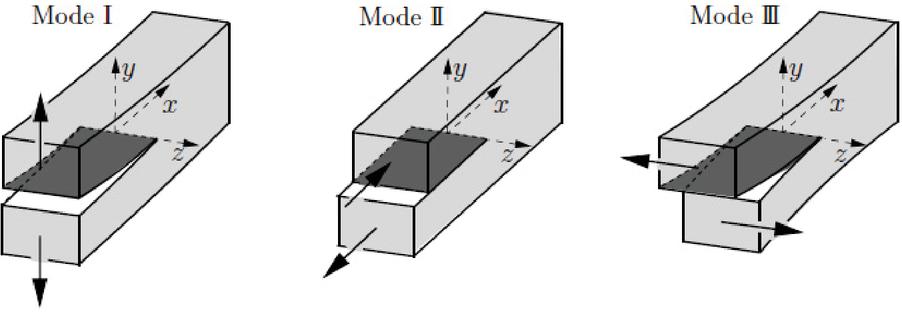
Figure 1 Primary loading modes in cracked specimens [7].
In natural rock masses, pre-existing cracks are frequently subjected to such combined-mode loading [9]. Thus, many different experimental studies and testing setups have been described in the fracture mechanics literature to evaluate the combined-mode fracture characteristics of rocks and other brittle materials. These studies provide critical insights into crack initiation and propagation mechanisms under complicated loading conditions that are essential for the design and analysis of engineering structures involving rock masses.
1.1 Literature Review
Much research has relied on both experimental and numerical methods to figure out how fractures behave in rocks and rock-like materials. The studies want to understand the role of microstructural features, loading, and environmental factors in the nucleation and growth of cracks. Liu et al. [10] examined granite with a coarse grain and an inverted U-shaped opening subjected to uniaxial compression by means of acoustic emission and moment tensor analysis. They found that microcracks mostly cluster in the vertical direction, and that shear cracks make up about 60% of the events, thus demonstrating the importance of stress concentration and cavity geometry in the mechanisms of fracture. Mardoukhi et al. [11] revealed that the main source of reduction in Balmoral Red granite tensile strength is the complexity of surface cracks that can be measured by fractal dimension, and dynamic loading further enhances this effect and reduces strain rate sensitivity.
There have been significant advancements in methods used to measure fracture parameters. Wang and Hu [12] introduced a simple method which involves notched three-point-bend samples to assess granite’s fracture toughness and tensile strength. They corroborated a fracture mechanics model that is capable of forecasting the behavior of smaller samples. Aliha and Ayatollahi [13] introduced a simple method which involves notched three-point-bend samples to ascertain granite’s fracture toughness as well as tensile strength. They corroborated a fracture mechanics model that is capable of forecasting the behavior of smaller samples. Aliha et al. [14] on mixed-mode fracture in Harsin marble with BD (Brazilian discs) as well as SCB (semi-circular bend) specimens, revealed that traditional single-curve mixed-mode criteria could not recognize specimen-specific variations while a generalized criterion considering geometry and loading conditions could explain both upper and lower bound envelopes. They have also been able to demonstrate how cracks progress at mixed-mode loading conditions. To find out the initial crack angles and critical loads in marble beams, Xeidakis et al. [15] carried out experimental three-point bending and finite element analysis, concluding that there is a very good correlation between theory and experiments. The numerical work of Aliha et al. [16] on cracked straight-through flat Brazilian disc (CSTFBD) specimens revealed the influence of specimen height as a main factor SIF along with -stress where the decrease in pure Mode II crack inclination for longer cracks and smaller heights was observed. Razavi et al. [5] demonstrated that the average strain energy density (ASED) criterion is capable of accurately predicting fracture loads in pre-cracked granite at mixed-Mode I/II loading.
The effect of specimen size as well as geometry has been emphasized in many studies. Akbardoost et al. [17] revealed that the Guiting limestone’s mixed-mode fracture resistance rises with the size of the sample and it can be very well anticipated by utilizing the modified maximum tangential stress (MMTS) criterion. Similarly, Chen et al. [18] determined in anisotropic Hualien marble, the mixed-mode fracture toughness was obtained using the boundary element method along with cracked ring tests. The factors of crack inclination, radius ratio, and orientation were all proven to have an effect on it. Additionally, temperature impact on rock fracture behavior has been shown to be considerable. Shimada [19] verified the occurrence of low- and high-pressure fractures in granite under triaxial loading up to 300∘C and pointed out the changes of failure mechanisms with increasing temperature. Guo et al. [20] added that marble heated to high temperature loses its fracture toughness, longitudinal wave velocity, and elastic modulus. They used acoustic emission (AE) and digital image correlation to reveal crack opening and strain fields that are dependent on temperature. It has been discovered from a score of studies that sandstone exhibits comprehensive mixed-mode fracture behavior under asymmetric loading. Zhang et al. [21] conducted a study on asymmetric semi-circular bend (ASCB) specimens and found that the effective fracture toughness (Keff) varies with normalized notch length showing initially an increase and then a decrease. They also recorded that the generalized maximum tangential strain (GMTSN) criterion was able to provide excellent predictions for Mode II-dominant loading. Zhao et al. [22] carried out investigations on ENDB and DENDC sandstone specimens under pure Mode I, combined I/III, as well as pure Mode III loading. The observed peak load was higher in Mode III than in Mode I; furthermore, Mode III displayed a similar increase in fracture energy. Furthermore, they observed that the three-dimensional modified mean strain energy density criterion is very effective in predicting mixed-Mode I/III fracture toughness, even in cases where the non-coplanar twist angle is not known. In summary, all studies conducted on microstructural features, specimen geometry, loading conditions, and environmental factors have shown that these factors are of great importance when it comes to the fractures starting and propagating in rocks. In addition, they throw light on the evolution of robust experimental and numerical criteria such as generalized maximum tangential stress (GMTS), GMTSN, MMTS, and ASED-based approaches for not only locating but also quantitatively describing mixed-mode fracture behavior with high accuracy, which leads to a deeper understanding of rock mechanics, geotechnical applications, and engineering design under complex stress states.
1.2 Research Gaps
Most of the existing research regarding fracture mechanics of rock materials have predominantly addressed Mode I loading, which is normally associated with tensile stresses. In practical situations, fractured rock structures are often exposed to combined Mode I/II loading, in which the failure can be caused by a mixture of tensile and shear stresses. Thus, it is of utmost importance to be able to accurately anticipate rock materials’ fracture behavior under mixed-mode loading in order to reveal these brittle materials’ failure processes. Experimentally studying the mechanics of fracture in natural rock is difficult because of the large size and irregular shape of the rocks. Moreover, conducting experiments on natural rocks under controlled laboratory conditions becomes more complicated. Therefore, the fracture’s behavior is examined in miniature specimens subjected to controlled conditions in a laboratory. Several kinds of specimens have been used for studying fractures in rocks. Usually, researchers construct a model where the crack in combined Mode I/II loading is at an angle and thus will require accurate fabrication and control of the crack location. Production of these specimens from brittle and hard rock materials generally entails the use of heavy machinery – coring machines and water-jet cutters – making the procedure both time-consuming and expensive. In order to overcome these restrictions, the current research presents innovative specimen geometry that not only eliminates the problems of specimen preparation and the generation of pre-inclined cracks but also provides a trustworthy analysis of mixed-Mode I/II fracture behavior. This strategy is designed to open up experimental research on rock fracture mechanics under authentic mixed-mode loading conditions, which is both convenient and reproducible.
1.3 Innovation
This study introduces key innovations to address existing challenges in investigating mixed-mode fracture behavior of brittle and hard materials, such as rocks. A new specimen geometry is described, which allows a more accurate and reliable evaluation of fracture under the combined Mode I/II loading without having to deal with the difficulties of making pre-inclined cracks. This geometry is much less complicated than BD and SCB types in terms of manufacturing process. Numerical methods as well as SIF calculations are employed to analyze the behavior of the cracks with great precision in terms of the loading conditions, thus giving very accurate information about the fracture mechanisms.
By applying maximum tangential stress (MTS) and GMTS criteria, the study predicts and compares fracture loads and crack propagation angles across different loading scenarios, offering greater insight into mixed-mode fracture processes in rocks.
1.4 Structure
This paper is organized in a structured manner. Section 1 discusses the significance of the fracture behavior in rocks, goes over the relevant literature, and points out the gaps in the research. The discussion of specimen geometry with cracks and numerical simulation using finite element technique through it is brought in Section 2. In Section 3, the levels of stress near the crack site are analyzed. In Section 4, the presentation of fracture standards is made along with their application i.e. MTS and GMTS. Section 5 is dedicated to displaying simulation results and discussing the different factors impact on crack growth. Section 6 summarizes the main ideas and the conclusions obtained from the study.
2 Specimen Geometry and Finite Element Simulation
The fracture and crack propagation behavior of materials is commonly investigated using standard specimen geometries reported in fracture mechanics literature. Usually, finite element simulations or experimental testing are the methods used to analyze the crack propagation in these kinds of samples. These shapes are mostly divided into two categories: internal fractures and edge fractures. Specimens such as BD feature internal cracks [23, 24], and both their fabrication and the introduction of initial cracks in brittle and hard materials require specialized equipment, including core drilling machines or water-jet cutters [4].
In contrast, edge-cracked specimens, such as four-point bending (FPB) [25], SCB [26, 27], and single-edge notch beam (SENB) [28, 29], are considerably easier to prepare and do not require specialized equipment. However, for edge-cracked geometries, achieving specific crack inclinations relative to the loading axis often necessary for pure Mode II loading or mixed-Mode I/II is challenging for brittle materials and demands precise instrumentation.
To overcome these practical limitations, the present study employs SENB geometry. This specimen can be fabricated easily using standard stone-cutting equipment and inherently features a vertical edge crack. Modification in the positions of the loading supports in relation to the notch leads to different loading conditions being applied without the formation of cracks that are pre-inclined. More specifically, if the supports are positioned in a symmetrical manner with the notch, the sample will be subjected to pure Mode I loading (Figure 2(a)). If the supports are placed asymmetrically, it will result in the application of pure Mode II loading or mixed-Mode I/II (Figure 2(b)).
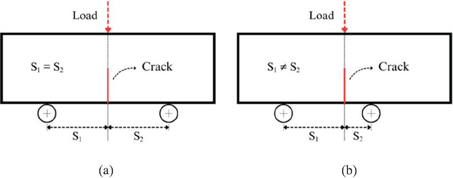
Figure 2 SENB sample support configurations: (a) symmetric supports for pure Mode I loading and (b) asymmetric supports for mixed-Mode I/II or pure Mode II loading.
Determining the appropriate support locations to achieve the desired loading requires careful consideration of the specimen and notch dimensions. In this paper, the finite element software ABAQUS was employed to precisely identify the support positions for each loading configuration, ensuring accurate simulation for the targeted mixed-mode fracture conditions.
In the present investigation, a rectangular specimen measuring 210 mm in length and 70 mm in width was modeled in two dimensions. Based on reports in the fracture mechanics literature, marble has a mainly brittle failure behavior, and its fracture process zone (FPZ) is comparatively large [30, 31]. Since there is no considerable plastic deformation before the fracture, marble was considered to be a homogeneous, linear-elastic material.
The mechanical properties used in the simulations included a Poisson’s ratio of 0.28 and a Young’s modulus of 70,000 MPa at as listed in Table 1 [20, 32]. The utilization of these elastic parameters is considered common labor in finite element analysis of different kinds of marble, which has been widely supported by the past research.
Table 1 Marble mechanical properties at 20∘C [20, 32]
| Elastic Modulus, | Tensile Strength, | Fracture Toughness, | |
| (MPa) | Poisson’s Ratio, | (MPa) | (MPa.mm0.5) |
| 70000 | 0.28 | 3.21 | 42.54 |
A vertical edge crack 35 mm in length was embedded in the SENB specimen at the center of the lower edge. The crack-to-width ratio was established as a/ which is a value that has been recommended by previous studies as an acceptable range for mixed-mode loading conditions [33]. A standard thickness of 16 mm was assigned to the sample which corresponds to the marble thickness usually used in applications in the industry [4]. Moreover, because the thickness is relatively small compared with the other specimen dimensions, plane stress conditions were adopted in the numerical simulations [33].
In order to set up the three-point bending arrangement, a concentrated compressive load was placed at the midpoint on the upper edge of the specimen. The lower edge was supported by two supports: the left support was set at a distance from the center and the right support was situated at a distance . The movement of the specimen at the left support was limited in both the horizontal and vertical directions, while vertical displacement was controlled at the right support.
The simulations made use of quadratic finite elements, and the crack tip area was mesh-refined stepwise so that the high stress gradients could be sensed accurately. The mesh’s total count was 17,420 elements plus 52,575 nodes, while the CPS8R element type was also incorporated. Also, mesh convergence analysis was executed to confirm the appropriate elements number used in the finite element model [5]. A representative view of the meshing scheme is shown in Figure 3.
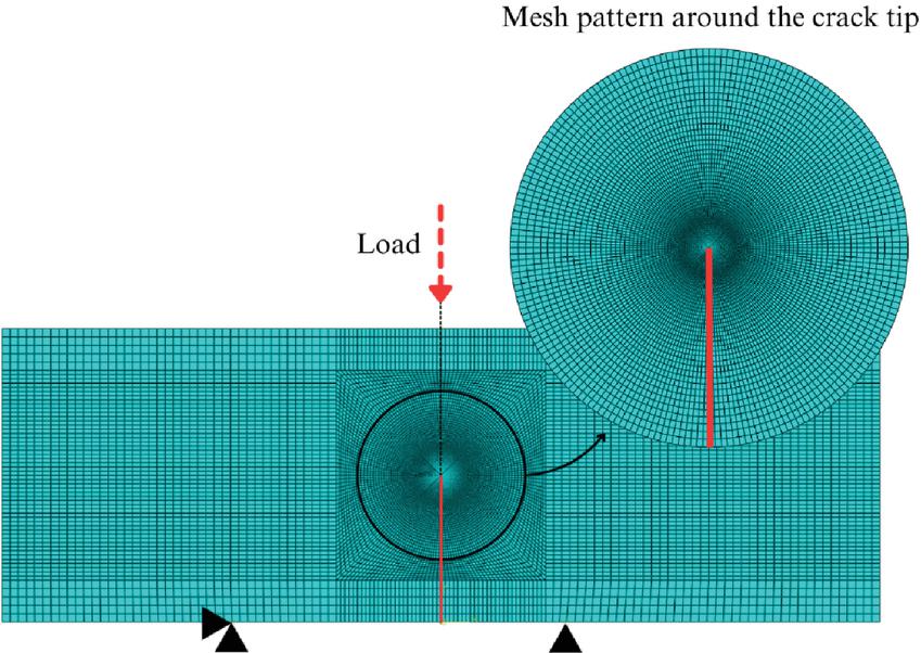
Figure 3 SENB sample finite element mesh, showing refined elements near the crack tip to capture stress concentration accurately (CPS8R elements).
It has been mentioned previously that the support’s location concerning the crack is the main factor to determine the loading mode created. Hence, the left support was consistently fixed at 50 mm from the centerline of the specimen in the following simulations, and the position of the right support was modified. For each value of , separate finite element simulations were performed, and the corresponding Mode I and Mode II SIFs, along with the -stress, were extracted from the ABAQUS output. These results are presented in Figure 4.
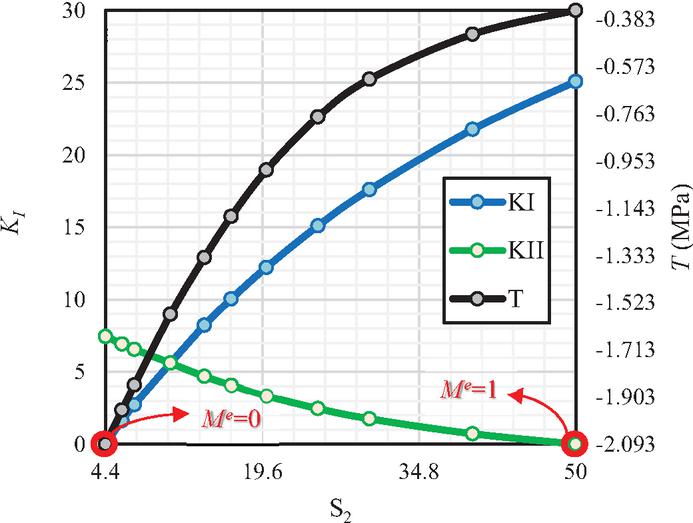
Figure 4 Variation of Mode I & II stress intensity factors and -stress for different right support positions .
The mode mixity parameter (Me) is a parameter that characterizes the total loading condition in terms of the proportions of the individual fracture modes. Its value is derived from Equation (1) [5]. When loading in Mode I only, the ratio is one , and for Mode II loading, it is zero . Me varies from 0 to 1 for mixed aspects I/II loading conditions.
| (1) |
In the current investigation, if the supports are symmetrically positioned concerning the crack , the sample receives pure Mode I loading as well as at the same time the Mode II SIF is zero. In contrast, the sample will experience either pure Mode II loading () or a mixed-Mode I/II situation if the supports are positioned asymmetrically .
The relevant values of , the SIF for Mode I and Mode II along with the -stress were obtained from the graphs displayed in Figure 4 for , 0.25, 0.5, 0.75, and 1 in order to examine the marble fracture features at different mixed-mode loading scenarios. These outcomes are presented in Table 2.
Table 2 Support positions , Mode I as well as Mode II SIFs, along with -stress for different mode mixities (, 0.25, 0.5, 0.75, 1) in SENB specimens
| (MPa.mm 0.5) | (MPa.mm0.5) | (MPa) | |||
| 1 | 50 | 50 | 25.08 | 0 | 0.35 |
| 0.75 | 50 | 16.6 | 10.05 | 4.07 | 1.18 |
| 0.5 | 50 | 10.7 | 5.62 | 5.62 | 1.57 |
| 0.25 | 50 | 7.2 | 2.73 | 6.56 | 1.86 |
| 0 | 50 | 4.4 | 0 | 7.45 | 2.09 |
3 Stress Distribution Around the Crack Tip
In specific configurations subjected to external loading, closed-form solutions can be used to analyze the stress fields in a body by assuming linear elastic and isotropic material behavior. Westergaard [34] and Williams [35] were pioneers in the research and publication of these types of solutions. By establishing a polar coordinate system with the origin at the crack tip, it is possible to demonstrate that the stress field in any linearly elastic cracked body is given by Equation (2).
| (2) |
where is the stress tensor with a constant , as well as a dimensionless function of denoted as . The description of variables and is represented in Figure 5. The -th term is denoted as a dimensionless function of , expressed as , with as the amplitude of high-order terms.
Geometry has an impact on higher-order terms; however, regardless of the specific arrangement, the solution always contains a major component that is same as . when approaching the crack tip , the remaining terms either stay finite or disappear, but this significant component increases to infinity. Hence, the tension close to the overall geometry of a fractured specimen has no bearing on the crack tip. Moreover, it can be proved that the displacement field in the vicinity of the crack tip behaves like . Equation (2) thus characterizes the stress singularity, since the stress becomes unbounded at .
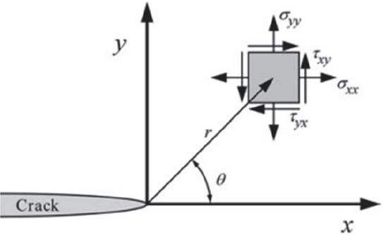
Figure 5 Coordinate system starts from the crack tip with z-direction perpendicular to the plane [7].
All loading modes exhibit the same singularity at the crack tip; however, the values of and depend on the specific loading mode. When the constant is substituted with SIF, Equation (3) expresses the connection between as well as SIF. In this equation, stands for SIF, and the loading modes are usually indicated with subscripts as , and .
| (3) |
The stress field in an isotropic, linearly elastic material at the crack’s tip with the Mode 1 stress loading shall be within Equations (4a)–(4c).
| (4a) | ||
| (4b) | ||
| (4c) |
The stress fields at the crack tip in a linearly elastic as well as isotropic material for Mode II loading are prescribed in Equations (5a)–(5c).
| (5a) | ||
| (5b) | ||
| (5c) |
The stress fields , and at the crack tip are identical for Mode I and Mode II loading and are defined by Equations (6c)–(6e).
| (6c) | ||
| (6d) | ||
| (6e) |
The stress fields at the crack tip in an isotropic and linearly elastic material for Mode III loading are given by Equations (7a)–(7f).
| (7a) | ||
| (7b) | ||
| (7c) | ||
| (7d) | ||
| (7e) | ||
| (7f) |
As per Equations (4a)–(7f), the SIFs for Modes I, II, and III are represented by , and , in that order. Furthermore, stands for Poisson’s ratio, and and are illustrated in Figure 5. In the case of mixed-mode loading (which means that there are several loading modes altogether), the individual stresses corresponding to each mode are combined according to the linear superposition principle.
| (8) |
Equations (4a)–(7f) show the individual stress fields of the three loading modes, that is, Mode I, Mode II, and Mode III [7].
4 Fracture Criteria
As per the literature available, marble shows linear elastic and homogeneous properties under typical laboratory conditions. Consequently, the linear elastic fracture mechanics (LEFM) model can be used to assess the fracture characteristics of marble specimen analysis. Among the commonly used fracture criteria within LEFM, in this research the MTS and GMTS criteria are utilized to estimate the angles of crack growth and the failure loads under mixed-Mode I/II loading. A comprehensive discussion on these criteria is provided below.
4.1 MTS Criterion
In their work, Erdogan and Sih [36] proposed the MTS criterion as a way to forecast fracture for mixed-Mode I/II loading. The stress distributions at the crack tip in Mode I of loading for a linearly elastic, isotropic material are given by Equations (4a)–(4c). Likewise, the stress fields for Mode II loading are given by Equations (5a)–(5c).
For loading conditions that combine different modes (like the case of simultaneous Mode I as well as Mode II loading), the separate stress components for each mode are added together based on the linear superposition principle. The stress fielder in polar coordinates can be written as in Equations (19a)–(19c) by using the stress tensor transformation relations from Equation (18).
| (18) |
| (19a) | ||
| (19b) | ||
| (19c) |
The tangential stress is subject to simplification by way of the trigonometric relations given in Equation (22), and the resulting simplified expression is presented in Equation (23).
| (22) | |
| (23) |
Based on the MTS criteria, the propagation of the crack is such that it follows the direction where the tangential stress reaches its peak value as the function of the angle near the crack tip [36]. To determine this MTS, the conditions given in Equation (24) must be satisfied. By applying these conditions to Equation (23) and solving the resulting expression analytically, Equation (25) is obtained, which defines the crack propagation angle.
| (24) | |
| (25) |
Moreover, Erdogan and Sih [36] claimed that when the tangential stress attains its maximum value, fracture happens. Therefore, by applying the angle of crack propagation into Equation (23), the relationship given in Equation (26) is obtained.
| (26) |
Researchers have noted that, at pure Mode I loading, the variables and are taken to be zero, and the value of for this case is defined as . By substituting these parameters into Equation (26), the expression given in Equation (27) is obtained.
| (27) |
By substituting Equation (27) into Equation (26), the resulting expression is given in Equation (28).
| (28) |
With linear elastic conditions assumed during the process of FEA, the stress elements will change proportionately with changes in applied loads. Therefore, the failure load based on the MTS criterion, denoted as PMTS, is predicted using a proportional relation between the material fracture toughness , the value of fracture toughness derived from the finite element method, and the vertical load applied, all of which are given by the Equation (29) [37].
| (29) |
4.2 GMTS Criterion
Smith et al. [38] introduced the GMTS criterion. The criterion was developed depending on tangential stress and is appropriate for assessing fracture in brittle fractured materials under mixed-Mode I/II loading. According to this approach, Equation (30) represents the tangential stress near the crack tip.
| (30) |
As can be seen, in this criterion the tangential stress expression includes not only the singular leading term but also the non-singular -stress term, whereas the MTS criterion neglects the -stress contribution. Based on GMTS criteria, the cracking occurs in the direction of highest tangential stress [38]. This maximum occurs when the conditions given in Equation (24) are satisfied. By applying these conditions to Equation (30) and solving analytically, the crack growth angle can be determined as expressed in Equation (31).
| (31) |
For a cracked body, the critical radius is defined as the radius of a circle centered at the crack tip and is considered an intrinsic material property. Equation (32) may be derived to extract the radius in-plane strain [39].
| (32) |
In this expression is a homogeneous tensile strength, while is fracture toughness. Table 1 provides the parameter values for the marble used in this study.
By the GMTS criterion, fracture appears in a specimen when the shear stress is maximum in the direction of crack growth represented by [40]. By substituting the crack growth angle into Equation (30), Equation (33) is obtained.
Researchers have stated that in pure Mode I, the parameters and are considered zero, and the value of for this case is defined as . By applying these parameters to Equation (33), Equation (34) is derived.
| (33) | ||
| (34) |
Subsequently, by combining Equations (33) and (34), Equation (35) is obtained, representing the maximum shear stress in the cracked specimen.
| (35) |
Since the finite element analysis assumes linear elastic behavior, the components of stress change in direct proportion to the applied load. As a result, the GMTS criterion fracture load, referred to as PGMTS, can be associated with the specimen’s fracture toughness , the finite element analysis-derived equivalent fracture toughness , and the applied vertical or compressive load through a direct proportionality, as shown in Equation (36) [37].
| (36) |
For consistency in the present formulation, two fracture toughness parameters are distinguished in this study. The parameter denotes the intrinsic material fracture toughness reported in Table 1, while represents the fracture toughness obtained from numerical simulations under different loading conditions based on the MTS and GMTS criteria. This notation is used throughout the analysis to clearly distinguish between the material property and the simulation-based fracture response.
5 Results
Table 3 presents the predicted fracture loads and crack propagation angles for various loading conditions based on the GMTS criterion and MTS criterion the for the SENB specimen. For improved visualization and comparison, these results are shown in Figures 6(a), (b), and 7.
Table 3 Predicted crack propagation angles and fracture loads for SENB samples at various loading conditions (, 0.25, 0.5, 0.75, 1) based on MTS and GMTS criteria
| MTS | GMTS | |||
| (N) | (N) | |||
| 1 | 1696.20 | 0.00 | 1696.20 | 0.00 |
| 0.75 | 3527.80 | 35.63 | 4041.10 | 8.95 |
| 0.5 | 4231.40 | 53.13 | 6658.90 | 10.45 |
| 0.25 | 4640.10 | 62.82 | 11610.00 | 10.89 |
| 0 | 4945.10 | 70.53 | 38124.00 | 11.46 |
Figure 6(a) shows the difference in the values of predicted fracture load as a function of the MTS and GMTS criteria in the case of a SENB sample subjected to various loadings such as Mode I loading , Mode II loading , and a mixture of both. The results indicate that the fracture load reaches its minimum at pure Mode I loading, demonstrating that the specimen exhibits the lowest resistance when the support points are positioned symmetrically relative to the crack. There is a load aspect which moves step by step from loading in Mode I to some loading in Mode II while the value decreases; correspondingly, the value of fracture load rises.
Nonetheless, the MTS standard forecasts that Mode II addition will lead to a smaller fracture load increase than that implied by the GMTS standard. For instance, as the loading situation shifts from entirely Mode I to mixed-mode at , the MTS standard predicts a 149.5% increase in fracture load, whereas the GMTS forecast indicates a much higher increase of 292.6%. Both criteria consistently confirm that the highest fracture load occurs at pure Mode II loading .
The reported rise in failure load along with greater Mode II involvement can be ascribed to a negative (compressive) -stress existing at the crack tip. In cases of geometries with fractures, while a negative -stress contributes to an increase in effective fracture toughness, whereas a positive -stress leads to its reduction. As displayed in Figure 4, the -stress is least compressive at pure Mode I loading and becomes increasingly compressive as the influence of Mode II grows, reaching its maximum magnitude at pure Mode II loading . Therefore, it seems logical that the failure loads are lowest under pure Mode I as well as highest under pure Mode II.
To further clarify these observations, Figure 6(b) compares the fracture load predictions from the two criteria. When the loading is pure Mode I or Mode I-dominant , the predictions of the two criteria are in close agreement. However, as the loading becomes Mode II-dominant or pure Mode II , the discrepancy between MTS and GMTS increases considerably.
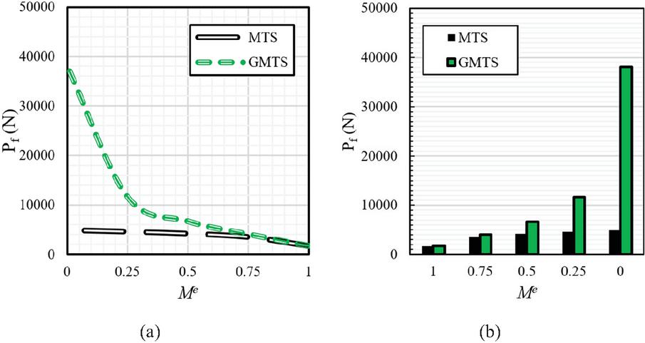
Figure 6 Predicted fracture load for SENB samples at mixed-Mode I/II loading (, 0.25, 0.5, 0.75, 1) using MTS and GMTS criteria.
Figure 6(b) also shows that the GMTS criterion predicts higher fracture loads at Mode II-dominant mixed-mode loading as well as pure Mode II loading . These configurations correspond to cases where the right support is located in close proximity to the crack tip, resulting in a strong interaction between the boundary conditions and the near-tip stress distribution.
The observed increase in fracture load under these conditions is consistent with the influence of the compressive (negative) -stress, which is enhanced as the Mode II contribution rises. Consequently, the discrepancy between the MTS and GMTS predictions is amplified in Mode II-dominant loading regimes due to the different treatment of the -stress term in the two criteria.
In this context, it is also significant to examine the stress pattern at the supports to ensure the validity of the predicted fracture mechanism. As shown in Figure 7, these compressive stresses are highly localized at the contact region and decay rapidly away from the supports, which is consistent with Saint-Venant’s principle. Furthermore, the maximum compressive stress in this case (approximately 106 MPa) remains below the uniaxial compressive strength of marble (155 MPa) [41], indicating that no local crushing or bearing failure occurs at the supports prior to global fracture.
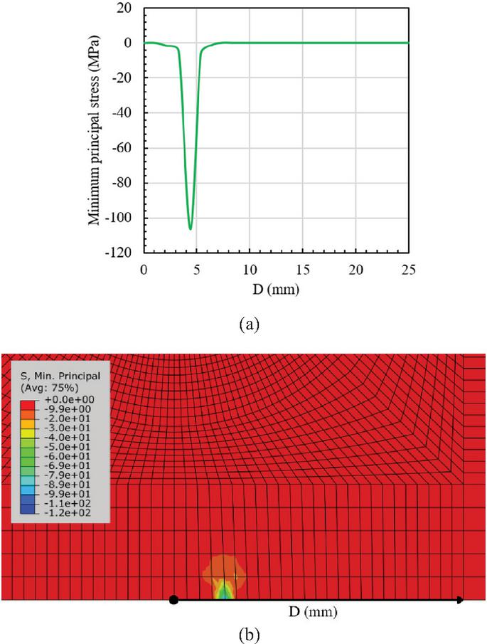
Figure 7 (a) Minimum principal stress variation along the sample bottom edge and (b) FE contour of minimum principal stress.
Figure 8 shows the tangential stress field in the FPZ at pure Mode II loading. As observed, the shear-dominated stress distribution remains localized around the crack tip, and the support reaction does not significantly alter the stress field governing crack propagation.
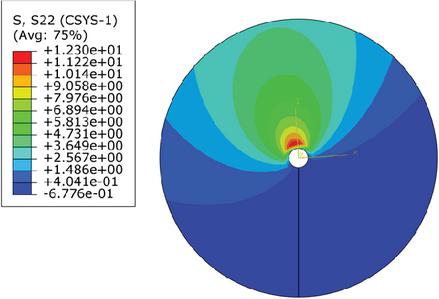
Figure 8 Tangential stress field in the fracture process zone at pure Mode II loading.
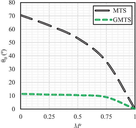
Figure 9 Crack propagation angles for SENB specimens were predicted at different loading by utilizing the MTS and GMTS criteria.
Notably, asymmetric support configurations have been widely adopted in recent studies to generate mixed-Mode (I/II) loading conditions, particularly in SCB-type samples. In several of these configurations, especially under pure Mode II loading conditions, the support is positioned in close proximity to the crack tip. Such configurations have been successfully applied to brittle materials such as polymethyl methacrylate (PMMA) and asphalt mixtures in previous experimental and numerical investigations [42, 43].
The predicted crack growth angles for the SENB sample subjected to the different loading conditions, namely pure Mode I , pure Mode II , as well as mixed-Mode I/II loading using the MTS and GMTS criteria are illustrated in Figure 9. The results point out that the crack during pure Mode I loading follows the original path, leading to a zero-growth angle. Such a finding is in agreement with earlier studies which have also claimed that at pure Mode I the crack propagation takes place along the crack line and the MTS as well as GMTS criteria are able to reflect this phenomenon accurately.
When Mode II’s contribution rises due to the lowering of the support position, the crack goes away from its original route, moving at an angle concerning the initial crack angle. The biggest angle of crack expansion is seen when Mode II loading is the only condition.
The difference between the two criteria arises from their treatment of the -stress at the crack tip. The -stress is not taken into account by the MTS criterion, which leads to the prediction of larger growth angles, while the GMTS criterion includes the effect of the non-singular -stress term, leading to different predictions of crack propagation angles under mixed-mode loading conditions. Therefore, the MTS-predicted crack growth angle increases dramatically from 0∘ for pure Mode I loading to 70.53∘ for pure Mode II loading. In contrast, the GMTS criterion predicts a change in the crack growth angle from 0∘ to 11.46∘ under the same loading conditions.
Given the limited availability of experimental studies on crack propagation in SENB specimens under asymmetric loading configurations and mixed-Mode I/II conditions, future experimental investigations are recommended to further validate and complement the present numerical findings. Such studies would provide valuable insight into the applicability of the GMTS and MTS criteria at complex loading in brittle materials such as marble.
6 Conclusion
Marble’s mixed-Mode I/II fracture behavior was the focus of the present study, in which experimental SENB specimens were supported by detailed finite element simulations. The SENB geometry was found to be an excellent tool for the investigation of different mode mixites due to its simple preparation and a vertical pre-crack, thus the complexity of angled cracks in the brittle rock was avoided. Finite element analyses employed provided accurate SIFs along with -stress values related to various loading configurations, as well as at the same time mesh convergence studies were performed to verify the accuracy of these results. GMTS and MTS criteria were applied for the estimation of fracture loads and crack growth angles. Results have revealed that the fracture load is minimal under pure Mode I loading as well as is increased by the introduction of Mode II, thereby becoming maximum at pure Mode II loading. The crack propagation directions also became larger with Mode II’s contribution, which is consistent with the negative -stress effect in increasing the resistance to fracture. This work demonstrates that SENB specimens complemented by state-of-the-art numerical analysis and the right fracture criteria represent an efficient and realistic tool for mixed-mode fracture investigation in brittle rocks. Such a method makes the crack behavior study at various loading more systematized, the complexity of the experiments is minimized, and the output becomes more useful for both predictive modeling and the fracture tests planning in rock mechanics.
References
[1] S. Ghouli, B. Bahrami, M. R. Ayatollahi, T. Driesner, and M. Nejati, “Introduction of a scaling factor for fracture toughness measurement of rocks using the semi-circular bend test,” Rock Mech. Rock Eng., vol. 54, no. 8, pp. 4041–4058, 2021, doi: 10.1007/s00603-021-02468-1.
[2] M. R. Ayatollahi, S. Ghouli, and B. Bahrami, “Experimental and theoretical fracture analyses for three biomaterials with dental applications,” J. Mech. Behav. Biomed. Mater., vol. 103, p. 103612, 2020, doi: 10.1016/j.jmbbm.2019.103612.
[3] L. Liu, H. Li, and X. Li, “A state-of-the-art review of mechanical characteristics and cracking processes of pre-cracked rocks under quasi-static compression,” J. Rock Mech. Geotech. Eng., vol. 14, no. 6, pp. 2034–2057, 2022, doi: 10.1016/j.jrmge.2022.03.013.
[4] M. R. M. Aliha, G. R. Hosseinpour, and M. R. Ayatollahi, “Application of cracked triangular specimen subjected to three-point bending for investigating fracture behavior of rock materials,” Rock Mech. Rock Eng., vol. 46, no. 5, pp. 1023–1034, 2013, doi: 10.1007/s00603-012-0325-z.
[5] N. Razavi, M. R. M. Aliha, and F. Berto, “Application of an average strain energy density criterion to obtain the mixed mode fracture load of granite rock tested with the cracked asymmetric four-point bend specimens,” Theor. Appl. Fract. Mech., vol. 97, pp. 419–425, 2018, doi: 10.1016/j.tafmec.2017.07.004.
[6] A. M. Al-Mukhtar and B. Merkel, “Simulation of the crack propagation in rocks using fracture mechanics approach,” J. Fail. Anal. Prev., vol. 15, no. 1, pp. 90–100, 2015, doi: 10.1007/s11668-014-9907-2.
[7] T. L. Anderson and T. L. Anderson, Fracture Mechanics: Fundamentals and Applications. CRC Press, 2005.
[8] J. Caicedo and A. Portela, “Direct computation of stress intensity factors in finite element method,” Eur. J. Comput. Mech., pp. 309–335, 2017.
[9] M. R. M. Aliha and M. R. Ayatollahi, “Mixed Mode I/II brittle fracture evaluation of marble using SCB specimen,” Procedia Eng., vol. 10, pp. 311–318, 2011, doi: 10.1016/j.proeng.2011.04.054.
[10] J.-P. Liu et al., “Cracking mechanisms in granite rocks subjected to uniaxial compression by moment tensor analysis of acoustic emission,” Theor. Appl. Fract. Mech., vol. 75, pp. 151–159, 2015, doi: 10.1016/j.tafmec.2014.12.006.
[11] A. Mardoukhi, Y. Mardoukhi, M. Hokka, and V.-T. Kuokkala, “Effects of heat shock on the dynamic tensile behavior of granitic rocks,” Rock Mech. Rock Eng., vol. 50, no. 5, pp. 1171–1182, 2017, doi: 10.1007/s00603-017-1168-4.
[12] Y. Wang and X. Hu, “Determination of tensile strength and fracture toughness of granite using notched three-point-bend samples,” Rock Mech. Rock Eng., vol. 50, no. 1, pp. 17–28, 2017, doi: 10.1007/s00603-016-1098-6.
[13] M. R. M. Aliha and M. R. Ayatollahi, “Rock fracture toughness study using cracked chevron notched Brazilian disc specimen under pure modes I and II loading – A statistical approach,” Theor. Appl. Fract. Mech., vol. 69, pp. 17–25, 2014, doi: 10.1016/j.tafmec.2013.1 1.008.
[14] M. R. M. Aliha, M. R. Ayatollahi, and J. Akbardoost, “Typical upper bound-lower bound mixed mode fracture resistance envelopes for rock material,” Rock Mech. Rock Eng., vol. 45, no. 1, pp. 65–74, 2012, doi: 10.1007/s00603-011-0167-0.
[15] G. S. Xeidakis, I. S. Samaras, D. A. Zacharopoulos, and G. E. Papakaliatakis, “Crack growth in a mixed-mode loading on marble beams under three-point bending,” Int. J. Fract., vol. 79, no. 2, pp. 197–208, 1996, doi: 10.1007/BF00032936.
[16] M. R. M. Aliha, R. Pakzad, and M. R. Ayatollhi, “Numerical analyses of a cracked straight-through flattened Brazilian disk specimen under mixed-mode loading,” J. Eng. Mech., vol. 140, no. 1, pp. 219–224, Jan. 2014, doi: 10.1061/(ASCE)EM.1943-7889.0000651.
[17] J. Akbardoost, M. R. Ayatollahi, M. R. M. Aliha, M. J. Pavier, and D. J. Smith, “Size-dependent fracture behavior of Guiting limestone under mixed mode loading,” Int. J. Rock Mech. Min. Sci., vol. 71, pp. 369–380, 2014, doi: 10.1016/j.ijrmms.2014.07.019.
[18] C.-H. Chen, C.-S. Chen, and J.-H. Wu, “Fracture toughness analysis on cracked ring disks of anisotropic rock,” Rock Mech. Rock Eng., vol. 41, no. 4, pp. 539–562, 2008, doi: 10.1007/s00603-007-0152-9.
[19] M. Shimada, “Confirmation of two types of fracture in granite deformed at temperatures to 300∘C,” Tectonophysics, vol. 211, no. 1, pp. 259–268, 1992, doi: 10.1016/0040-1951(92)90063-C.
[20] Q. Guo, H. Su, J. Liu, Q. Yin, H. Jing, and L. Yu, “An experimental study on the fracture behaviors of marble specimens subjected to high temperature treatment,” Eng. Fract. Mech., vol. 225, p. 106862, 2020, doi: 10.1016/j.engfracmech.2019.106862.
[21] W. Zhang, W. Hua, M. Zhou, F. He, Y. Xu, and S. Dong, “Experimental study on the fracture characteristics of sandstone under asymmetric load by using a semi-circular bending specimen,” Theor. Appl. Fract. Mech., vol. 130, p. 104315, 2024, doi: 10.1016/j.tafmec.2024.104315.
[22] Y. Zhao, K. Zheng, and C. Wang, “Mixed-Mode I/III fracture BT – Rock fracture mechanics and fracture criteria,” Y. Zhao, K. Zheng, and C. Wang, Eds., Singapore: Springer Nature Singapore, pp. 89–112, 2024, doi: 10.1007/978-981-97-5822-7_6.
[23] Y. Xu, F. Dai, T. Zhao, N. Xu, and Y. Liu, “Fracture toughness determination of cracked chevron notched Brazilian disc rock specimen via Griffith energy criterion incorporating realistic fracture profiles,” Rock Mech. Rock Eng., vol. 49, no. 8, pp. 3083–3093, 2016, doi: 10.1007/s00603-016-0978-0.
[24] G. Giambanco, M. Puccia, and A. Spada, “Numerical simulation of experimental fracture in BD and CCNBD sandstone specimens using the Advanced Augmented-FEM,” Eng. Fract. Mech., vol. 330, p. 111694, 2025, doi: 10.1016/j.engfracmech.2025.111694.
[25] M. G. Salomon, F. Meftah, and J.-M. Reynouard, “Mixed mode fracture of a higher order beam model in gradient-dependent plasticity,” Eur. J. Comput. Mech., pp. 831–839, 2004.
[26] M. D. Kuruppu and K. P. Chong, “Fracture toughness testing of brittle materials using semi-circular bend (SCB) specimen,” Eng. Fract. Mech., vol. 91, pp. 133–150, 2012, doi: 10.1016/j.engfracmech.2012.01.013.
[27] Y. Obara, K. Nakamura, S. Yoshioka, A. Sainoki, and A. Kasai, “Crack front geometry and stress intensity factor of semi-circular bend specimens with straight through and chevron notches,” Rock Mech. Rock Eng., vol. 53, no. 2, pp. 723–738, 2020, doi: 10.1007/s00603-019-01 930-5.
[28] Q. Lin, X. Bian, P.-Z. Pan, Y. Gao, and Y. Lu, “Criterion of local symmetry visualized in small eccentric single edge notched bend (E-SENB) rock specimens,” Eng. Fract. Mech., vol. 248, p. 107709, 2021, doi: 10.1016/j.engfracmech.2021.107709.
[29] M. R. Ayatollahi, B. Bahrami, A. M. Mirzaei, and M. Yazid Yahya, “Effects of support friction on Mode I stress intensity factor and fracture toughness in SENB testing,” Theor. Appl. Fract. Mech., vol. 103, p. 102288, 2019, doi: 10.1016/j.tafmec.2019.102288.
[30] L. Zhang et al., “Experimental and numerical investigations on the mixed-mode fracture of granite under offset three-point bending loads,” Rock Mech. Rock Eng., 2025, doi: 10.1007/s00603-025-04871-4.
[31] B. Afrasiabian and M. Eftekhari, “Prediction of Mode I fracture toughness of rock using linear multiple regression and gene expression programming,” J. Rock Mech. Geotech. Eng., vol. 14, no. 5, pp. 1421–1432, 2022, doi: 10.1016/j.jrmge.2022.03.008.
[32] B. N. Whittaker, R. N. Singh, and G. Sun, Rock Fracture Mechanics: Principles, Design and Applications. 1992.
[33] A. Jahanbani, S. Pirmohammad, and M. R. Ayatollahi, “Effect of friction at crack surfaces on the fracture behavior of particleboard under compression-shear loading,” Theor. Appl. Fract. Mech., vol. 141, p. 105269, 2026, doi: 10.1016/j.tafmec.2025.105269.
[34] H. M. Westergaard, “Bearing pressures and cracks: bearing pressures through a slightly waved surface or through a nearly flat part of a cylinder, and related problems of cracks,” J. Appl. Mech., vol. 6, no. 2, pp. A49–A53, Mar. 2021, doi: 10.1115/1.4008919.
[35] M. L. Williams, “On the stress distribution at the base of a stationary crack,” J. Appl. Mech., vol. 24, no. 1, pp. 109–114, Jun. 2021, doi: 10.1115/1.4011454.
[36] F. Erdogan and G. C. Sih, “On the crack extension in plates under plane loading and transverse shear,” J. Basic Eng., vol. 85, no. 4, pp. 519–525, Dec. 1963, doi: 10.1115/1.3656897.
[37] M. Cai, “Fracture initiation and propagation in a Brazilian disc with a plane interface: a numerical study,” Rock Mech. Rock Eng., vol. 46, no. 2, pp. 289–302, 2013, doi: 10.1007/s00603-012-0331-1.
[38] D. J. Smith, M. R. Ayatollahi, and M. J. Pavier, “The role of T-stress in brittle fracture for linear elastic materials under mixed-mode loading,” Fatigue Fract. Eng. Mater. Struct., vol. 24, no. 2, pp. 137–150, 2001.
[39] R. A. Schmidt, “A microcrack model and its significance to hydraulic fracturing and fracture toughness testing,” in 21st U.S. Symposium on Rock Mechanics (USRMS), Rolla, Missouri, May 1980.
[40] M. R. Ayatollahi and M. R. M. Aliha, “Mixed mode fracture analysis of polycrystalline graphite – A modified MTS criterion,” Carbon N. Y., vol. 46, no. 10, pp. 1302–1308, 2008, doi: 10.1016/j.carbon.2008. 05.008.
[41] Y. Xu, G. Zhao, X. Li, B. Wu, and K. Xia, “Influences of notch width and notch-tip angle on the fracture toughness measurement using the semi-circular bend (SCB) specimen,” Eng. Fract. Mech., vol. 281, p. 109098, 2023, doi: 10.1016/j.engfracmech.2023.109098.
[42] M. Fakhri, E. Haghighat Kharrazi, and M. R. M. Aliha, “Mixed mode tensile – In-plane shear fracture energy determination for hot mix asphalt mixtures under intermediate temperature conditions,” Eng. Fract. Mech., vol. 192, pp. 98–113, 2018, doi: 10.1016/j.engfracmech.2018.02.007.
[43] R. Negru, L. Marsavina, H. Filipescu, and N. Pasca, “Investigation of mixed Mode I/II brittle fracture using ASCB specimen,” Int. J. Fract., vol. 181, no. 1, pp. 155–161, 2013, doi: 10.1007/s10704-013-9 830-7.
Biographies

Yanxiang Chen, female, born in Yongzhou, Hunan Province, is a member of the Communist Party of China. She holds a doctoral degree and is a senior engineer as well as a National Class-1 Certified Structural Engineer. In recent years, she has published more than 10 academic papers in domestic and international journals. She has been involved in two projects supported by the National Natural Science Foundation of China and two educational reform projects funded by the Provincial Department of Education. Additionally, she has led two municipal-level research projects, guided students in one provincial-level innovative research program, and directed one university-level high-quality course. Her main research focuses on monitoring and early warning of unstable rock masses, rock mechanics, and engineering. She teaches the courses Fundamental Principles of Concrete Structures and Building Information Modeling (BIM).

Enping Guo was born in Linfen, Shanxi, China, in 1987. She is an associate professor in Hunan Institute of Science and Engineering. Her master’s degree is from Hebei University of Engineering. Her research interest is structural engineering.

Linhua Huang was born in Yongzhou, Hunan, China, in 1986. He is a lecturer in Hunan University of Science and Engineering. His master’s degree is from Hunan Institute of Science and Engineering. His research interest is tunnel engineering.

Song Li was born in Yongzhou, Hunan, China, in 1985. He is an associate professor in Hunan University of Science and Engineering. His master’s and doctor’s degree are from Hunan Institute of Science and Engineering. His research interest is rock mechanics.
European Journal of Computational Mechanics, Vol. 35_2, 73–102
doi: 10.13052/ejcm2642-2085.3521
© 2026 River Publishers