Performance Evaluation Research of Digital Twin Model of Knife Gate Based on Finite Element Analysis Under Temperature Rise
Long Na and Gan Rundong*
Digital Intelligence Operation Centre, Guizhou Power Grid Co. Ltd., Guiyang 550000, Guizhou, China
E-mail: 984791945@qq.com; ganrundong10@outlook.com
*Corresponding Author
Received 16 July 2026; Accepted 11 September 2026
Abstract
Knife gate valves are widely used in industrial systems for regulating the flow of liquids, gases, and slurries under demanding operating conditions. Continuous exposure to elevated temperatures can cause thermal expansion, material degradation, stress accumulation, and structural deformation, reducing valve performance and increasing failure risk. This study proposes a Digital Twin-based thermo-mechanical performance evaluation framework integrated with finite element analysis (FEA) for knife gate valves under progressive thermal loading. Five operating temperature cases of 50∘C, 100∘C, 150∘C, 200∘C, and 250∘C were evaluated to characterize temperature distribution, heat flow, temperature-dependent yield strength, thermal and mechanical stress, deformation, safety factor, actuator torque, and seal pressure. The results demonstrate progressive thermo-mechanical degradation with increasing temperature. At 250∘C, the maximum induced stress reaches 246.45 MPa, exceeding the temperature-dependent yield strength of 235.2 MPa, while the safety factor decreases to 0.95 and deformation increases to 0.80682 mm. The required actuator torque increases to 1414.56 Nm, accompanied by a reduction in seal pressure to 1.069 MPa, a decline in valve health score from 100% to 55%, and a reduction in remaining useful life from 74.57 to 24.14 years. The Digital Twin consequently identifies the highest-temperature condition as a warning state, indicating increased structural and operational risk. The primary contribution of this work is the simultaneous prediction of stress, deformation, safety factor, torque, and remaining useful life within a single unified Digital Twin–FEA model.
Keywords: Digital twin, finite element analysis, knife gate valve, thermal stress, predictive maintenance.
1 Introduction
Knife gate valves are very important in some industrial operations especially in the operations of fluid handling and control of liquids, slurries, and flowing media like water treatment, mining, and petrochemical plants [1]. Such valves are subjected to different working conditions, and temperature changes are one of the popular factors affecting performance of such valves [2]. Temperature increases during operation, and this significantly alters the material properties of the valve components, including the body, gate, and actuator [3]. These parts might undergo thermal expansion, alterations in material strength, deformation, and possible failure owing to thermal stress [4]. To ensure the reliability, safety, and longevity of such critical components, the capability to precisely predict knife gate valve performance at higher temperatures is essential [5]. In this respect, the further use of such tools as Digital Twin models and finite element analysis (FEA) gains even more importance [6]. A Digital Twin represents a virtual representation of the valve system, which can be simulated and analyzed dynamically, and FEA will assist in the response of the valve to thermal loads to ensure that excessive deformation (cracks or over excessive deformation) are prevented [7].
Industrial adoption of Digital Twin technology is expanding across high-temperature process industries, where reliable equipment operation is essential for safety and continuity. In power generation, Digital Twin models combined with machine learning support predictive maintenance by identifying operational deviations and reliability trends [8]. In mining and mineral processing, knife gate valves handling abrasive slurries may experience coupled thermal, mechanical, and wear effects, making Digital Twin-based monitoring valuable for reducing unplanned shutdowns and improving maintenance planning. Similarly, petrochemical and process industries have developed Digital Twin frameworks for industrial valves that integrate sensing with model-based condition assessment [9]. These applications demonstrate how Digital Twins support the transition from reactive to condition-based and predictive maintenance through continuous monitoring and degradation analysis. Accordingly, integrating Digital Twin technology with thermo-mechanical FEA provides a promising approach for evaluating knife gate valve reliability under elevated-temperature operating conditions.
Various procedures have been suggested to examine the performance of knife gate valve under thermal loading [10]. Conventional approaches are based on models of analysis, in which simplified assumptions are made regarding the temperature field and material characteristics in an attempt to model thermal stresses and deformations [11]. Although such techniques offer a simple insight into the workings of the valve [12], they are not always accurate enough to model practical conditions particularly where complicated geometries or non-linear material characteristics are involved [13]. The popularity of FEA has risen because of the capacity to develop complex valves geometry, as well as, predict temperature distribution, stress and deformation with a high degree of accuracy [14–16] Nevertheless, FEA does not offer live insights and a predictive maintenance mechanism as a tool of operational safety [17]. The current methods of predictive maintenance usually use the isolated data or fixed simulations, which cannot measure the dynamic performance of the valve operation [18]. Moreover, the combination of FEA with monitoring systems as a Digital Twin is a relatively unexplored field, and the current approaches do not offer an inclusive evaluation that will consider the temperature-dependent material behavior and working performance [19].
A sensor-integrated Digital Twin for an industrial valve has been developed, combining a physical test bench with real-time data acquisition to enable predictive maintenance decision-making [20]. Similarly, data-driven Digital Twin architectures using deep learning have been applied for predictive maintenance in manufacturing systems [21], while distributed Digital Twin frameworks leveraging fog computing have been proposed to enable real-time condition monitoring and health management of industrial components [22]. Broader systematic reviews confirm the rapid growth of Digital Twin and predictive maintenance research [23], reflecting increasing industrial reliance on these methods. However, these valve- and equipment-focused Digital Twin implementations generally rely on sensor-driven or purely data-based models with simplified or isothermal structural assumptions, and do not incorporate temperature-dependent material behavior into a coupled thermo-mechanical finite element formulation.
The proposed framework addresses the shortcomings of current techniques because the Digital Twin modeling is combined with FEA to offer a dynamic and live assessment of the knife gate valve in different temperature conditions. The framework guarantees higher prediction accuracy in valve performance by providing temperature-dependent material properties and simulating thermal stresses and deformations with the FEA. Moreover, the combination with predictive maintenance can continuously monitor and pro-actively manage the health of the valve, covering the gaps in the live prediction of failures. The originality of this method is that it can develop a complete virtual model simulating both the thermal and mechanical characteristics of the valve to enable engineers to have all the insights needed to optimize the performance, avoid failures, and improve safety.
The remainder of this paper is organized as follows. Section 2 presents a review of literature research on thermal, structural, and Digital Twin-based analysis of industrial valves. Section 3 develops the problem statement by defining the issues of thermo-mechanical degradation and reliability of knife gate valves at high temperatures. Section 4 describes the proposed system architecture, including the Digital Twin framework and the conjoined thermo-mechanical FEA approach. Section 5 reports the simulation results and discussion of thermal, structural, and operational performance. Section 6 summarizes the study, highlighting the major findings along with directions for future research.
2 Related Works
Mills et al. [20] examined the advanced designs of falling particle receivers in concentrating solar power application that have shown that particle outlet temperatures of about 800∘C are achievable with high thermal efficiencies and also with the closed-loop temperature regulation that significantly reduces heat losses. Piechota et al. [21] conducted experimental results that established the errors of measurements of the clamp-on ultrasonic flow meters installed at the downstream of a knife gate valve as effectively compensated by a correction factor which allows the measurement of the flow velocity accurately even at shorter straight-pipe lengths under disturbed flow conditions. Marra et al. [26] introduced a Historical Digital Twin-based system that combines laser scanning and numerical modeling to measure stress states of dynamic behavior of the museum sculptures, which shows that the use of the digital replicas can enhance the accuracy and reliability of conservation and maintenance approaches towards cultural heritage assets. Rojas-Sola and Barranco-Molina [27] examined the mechanical behavior of a historically significant crosshead steam engine through a finite element based analysis, as a static analysis, in which was determined that would allow of pressures that will provide acceptable von Mises stresses, limited displacements and acceptable ranges of safety factors were determined that would allow the engine to operate safely and reliably.
Zhang et al. [28] created a Digital Twin of the VARIM composite manufacturing process based on machine learning and demonstrated that a deep neural network that has been trained on high-fidelity simulations can predict the spatio-temporal temperature distributions with high accuracy and fast speed, which can be effectively used to optimize and control the process. Kang et al. [29] experimented on the thermally induced operating point drift in servo valves, modeled with a whole-valve transfer function and multiphysics models. They found that asymmetric fitting of armature and nozzle and temperature-dependent structural and fluid changes are the major causes of nonlinear displacement and pressure variations. Rojas-Sola and Barranco-Molina [30] evaluated the structural viability of a two-cylinder steam engine of complex nature, as based on the finite element-based static analysis and found the optimal operating pressure range that keeps von Mises stresses and safety factors within the reasonable mechanical design ranges. Gonzalez-Morales et al. [31] investigated transient multi-phase flows in reverse tapered Ladle Shrouds using CFD to predict turbulence, air ingress, and steel splashing during start-up.
Wang et al. [32] examined the performance of cracks on the subsea connector metal sealing rings by modelling them through a FEA to determine the stress intensity factor and the long-term sealing performance. Lewis et al. [33] reviewed the use of FEA in fracture fixation noting the development of models, validation issues, and implant stress and bone strain predictions. Kardani et al. [34] proposed a hybrid stacking ensemble using FEA-generated and field data to enhance slope stability prediction, outperforming individual machine learning methods. Wang et al. [35] designed a multi-sensor fusion method to predict tool wear using a high accuracy and noise reduction adaptability to machining process with a ResNet-LSTM. Rojas-Sola and Gutiérrez-Antúnez [36] performed an analysis on two-cylinder compound vertical steam engine through FEA to identify the maximum vapor pressure and to conduct a safe operation under the critical start-up conditions. Marin et al. [37] used finite element methods to nonlinear hyperbolic bioheat equations to find temperature distributions and important parameters to use in effective hyperthermia tumor therapies. Gholami et al. [38] proposed the use of deep learning models with FEA to determine mechanical properties of BG-collagen composite hydrogels through microstructure images with high precision.
Computational and experimental studies have been used in engineering and science, e.g. design of optimized particle receivers to achieve high-energy factor solar power, correction of ultrasonic flow measurements, Digital Twin models to simulate cultural heritage, and a FEA of steam engines, tool wear, subsea connectors, fracture fixation, slope stability, hyperthermia treatments, and composite hydrogels, often by incorporating machine learning or CFD to improve prediction and operational safety.
3 Problem Statement
Current thermal-mechanical analysis models of industrial valves generally presuppose temperature-insensitive material characteristics, simplified geometry, and coupled thermal or structural analysis [29]. These methods are not able to reflect material softening at higher temperatures, localization of stress under coupled thermal-mechanical load, and progressive safety-factor degradation resulting in incorrect prediction of risk of failure and unreliable operational decision-making in extreme service conditions [32].
To overcome these drawbacks, the proposed framework will combine temperature-dependent material characteristics and coupled thermal-structural FEA in a single modeling strategy. The framework allows the correct determination of critically important zones, the early prediction of yielding onset, and the successful determination of structural safety in high-temperature operating conditions by simulating realistic heat transfer, stress evolution, and deformation behavior in a variety of operating conditions.
3.1 Objectives
• Develop a comprehensive thermo-mechanical analysis framework to evaluate the structural integrity and operational safety of a knife gate valve under elevated temperature conditions.
• Apply thermo-structural datasets generated by simulation realized using Digital Twins in FEA through several temperature-dependent operating cases.
• Implement temperature-dependent thermal analysis in the determination of heat transfer, temperature distribution and material property degradation in progressive thermal loading.
• Apply coupled structural FEA incorporating temperature-dependent yield behavior to assess stress evolution, deformation, safety factor reduction, and failure risk.
4 System Architecture
The methodology adopted in this study follows a sequential thermo-mechanical Digital Twin workflow, structured to progressively build from geometric modeling to operational risk assessment. First, the valve geometry and material dataset are imported and prepared through mesh generation and refinement. Second, thermal FEA is performed to determine temperature distribution, heat flow, and temperature-dependent yield strength under progressive thermal loading. Third, the resulting temperature field is coupled with mechanical loading in a thermo-mechanical FEA to evaluate induced stress, deformation, and safety factor. Fourth, these physics-based outputs are translated into operational performance indicators, including actuator torque requirement and seal pressure degradation, to assess functional and structural risk. Finally, all thermal, structural, and operational results are integrated into a Digital Twin layer that performs rule-based fault detection and predicts health status and remaining useful life across the evaluated operating conditions. This structured workflow ensures that each stage of analysis builds directly on the outputs of the preceding stage, enabling a fully coupled and physically consistent evaluation of knife gate valve performance under elevated-temperature operation.
The system architecture is created based on the thermo-mechanical analysis system driven by a Digital Twin of a knife gate valve using the manufacturer supplied dataset developed in the 3Dfindit repository that provides the correct geometry and material specifications of the valve body, gate, and seat. The architecture starts with geometry import and mesh preprocessing where the CAD model is refined and cleaned with refined meshing in the areas of interest as the gate to seat interface and load-bearing areas. Material properties and operational boundary conditions that are controlled by temperature are next allocated and thermal FEA is then used to calculate temperature distribution, heat flow, hot spots, and thermal stress. Temperature fields are then coupled with a mechanical loading, such as internal pressure and frictional contact, to model thermo-mechanical FEA to assess stress, deformation, safety factor, and risk of failure. Such physics-based outputs are then incorporated into the layer of a Digital Twin, and the operational parameters actuator torque, seal pressure, health index, remaining useful life, and fault warnings are forecasted and monitored at different temperatures. Every simulation, after-processing, and Digital Twin assessment is conducted through a computational and visualization setting designed in MATLAB. Figure 1 shows Digital Twin based thermo-mechanical system architecture for knife gate valve performance evaluation.
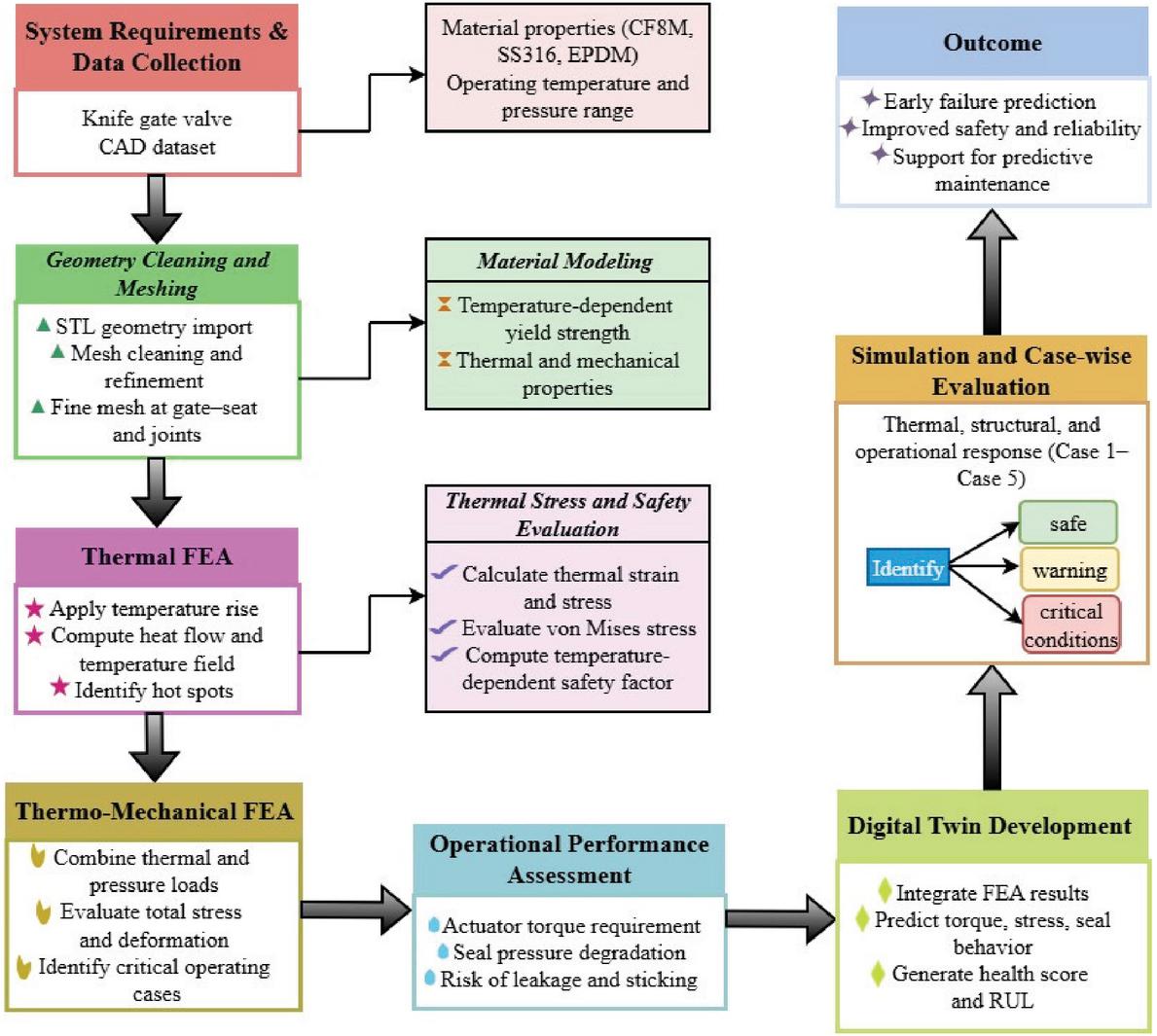
Figure 1 Digital Twin-based thermo-mechanical system architecture for knife gate valve performance evaluation.
4.1 System Requirements and Data Collection
The knife gate valve (CF8M stainless steel body, 316 stainless steel gate, EPDM seat) dataset [39] available in the 3Dfindit Digital Twin repository. The dataset provided by the manufacturer has the correct depersonalization of the valve body, the valve gate, the valve seat, and the actuator interface that allows a stable finite element discretization in thermo-mechanical analysis.
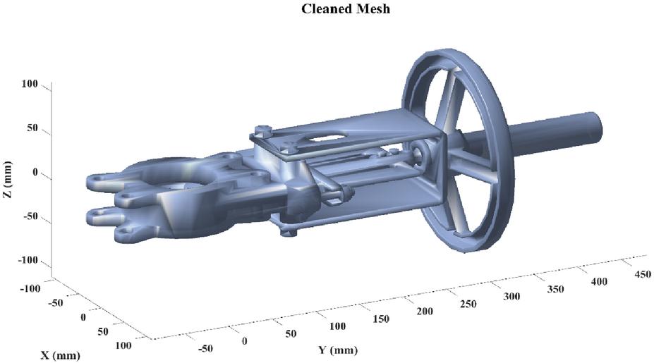
Figure 2 Cleaned mesh of the knife gate valve.
The imported geometry was processed to generate a cleaned and quality-verified finite element mesh, as shown in Figure 2. To provide numerical stability and proper stress transfer, mesh refinement was used in areas of critical concern, especially at the gate-seat contact interface, actuator connection areas, and load bearing structural features. Preprocessing was done to eliminate distorted elements and non-manifold features to achieve better convergence behavior and solution accuracy. The knife gate valve uses CF8M stainless steel for the pressure-bearing body, SS316 stainless steel for the gate, and EPDM elastomer for the sealing seat. Material selection reflects each component’s functional role. The model considers density, Young’s modulus, Poisson’s ratio, thermal conductivity, and thermal expansion. Temperature-dependent yield strength is included for the metallic components, using a reference strength of 290 MPa and a degradation coefficient of 0.4 MPa/∘C. EPDM is modeled primarily for its thermal and contact-sealing behavior. This material-specific approach evaluates thermal expansion, structural deformation, strength reduction, and gateseat interaction during valve operation.
Table 1 Material properties and representation of the principal knife gate valve components. CTE Coefficient of Thermal Expansion
| Young’s | Thermal | ||||||
| Density | Modulus | Poisson’s | Conductivity | CTE | Material Behavior | ||
| Material | Component | ) | (GPa) | Ratio | () | ) | Considered |
| CF8M | Valve body | 7750 | 193 | 0.30 | 15.0 | 16.0 | Temperature-dependent yield strength |
| SS316 | Gate | 8000 | 193 | 0.30 | 16.3 | 15.9 | Temperature-dependent yield strength |
| EPDM | Sealing seat | 1100 | 0.007–0.020* | 0.49* | 0.25 | 150–250 | Temperature-dependent contact/sealing response |
Table 1 summarizes the material properties and functional representation of CF8M, SS316, and EPDM used for the knife gate valve. It identifies the component-specific mechanical and thermal properties, including density, elastic modulus, Poisson’s ratio, thermal conductivity, CTE, and temperature-dependent yield or sealing behavior. The cleaned mesh had temperature-dependent material properties and operational boundary conditions, such as pressure limits, temperature range, and actuator torque limits, implemented to offer a solid basis to the subsequent sections of the thermal and coupled thermo-mechanical FEA. The temperature dependent yield strength captures the thermal softening of SS316 stainless steel and is given in Equation (1):
| (1) |
where is the yield strength at temperature t, is the yield strength at 20∘C (290 is the yield degradation coefficient , and is the reference temperature (20∘C). This linear form is adopted because it captures the dominant first-order softening trend of SS316 within the studied temperature range, while the lower-bound condition prevents non-physical strength values at extrapolated high temperatures.
4.2 Perform Thermal FEA
FEA is used to study the thermal behavior of the knife gate valve under thermal rise and thus know the temperature gradient, the hot spots, and give thermal input to the thermo-mechanical analysis.
4.2.1 Geometry preparation and meshing
The 3D CAD model of the valve is introduced into the FEA program and converted to a high-quality mesh. The design of critical regions, including, but not limited to, the gate-seat interface, actuator spindle, and thin walls, is optimized to capture local temperature gradient and hot spots at a high level of accuracy. The geometry extraction on STL is expressed in Equation (2):
| (2) |
where denotes valve length, the maximum diameter, the radius, and the estimated wall thickness. These are derived directly from the STL bounding box , because this provides a fast and reliable geometric approximation without requiring manual dimensioning of the CAD model.
Volume and mass estimates give preliminary confirmation of material assignment that is stated in the form of an Equation (3):
| (3) |
where denotes valve volume, the mass, and the material density. The cylindrical approximation is used since it provides a reasonable first-order estimate of mass sufficient for preliminary material assignment, prior to detailed finite element discretization.
STL triangles are calculated in summing up the total surface area to use in thermal calculations and this value is written in the form of Equation (4):
| (4) |
where is the valve length, is the maximum valve diameter, is the valve radius, is the estimated wall thickness, is the valve volume, is the valve mass, is the material density, is the total surface area of the valve, is the area of an individual STL triangle, and are the vertex coordinates of the STL triangle. A denotes total surface area and the area of an individual STL facet, computed from the vertex vectors v1, v2, v3. Summing triangular facets directly uses the discretized STL mesh already available from geometry import, avoiding a separate analytical surface formulation.
4.2.2 Boundary conditions and thermal loads
The valve is subjected to a temperature rise from ambient to the maximum operating temperature . Both steady and transient thermal simulations are done to record end-of-time and time-dependent temperature fields. The conductance and convection resistances can be modeled in the Equation (5):
| (5) |
where and denote conduction and convection thermal resistance, respectively, with as thermal conductivity, as convection coefficient, and as surface area. These are modeled as a series thermal network () because heat must pass sequentially through the solid wall before dissipating to the surrounding environment.
The rate of heat flow across the valve is as indicated in Equation (6):
| (6) |
where is the thermal conduction resistance, is the thermal convection resistance, is the wall thickness, is the temperature difference between and , and denotes the heat flow rate. Expressing as follows the thermal-electrical analogy, allowing heat transfer to be quantified using the same resistance terms defined in Equation (5).
4.2.3 Temperature field distribution
The modeling is done using normalized axial and radial coordinates in the case of non-uniform heat dissipation of a valve body at high temperature conditions. This formulation accounts realistic thermal gradients and allows localized hot spots that could be of concern to structural integrity and sealing performance to be identified. The coordinates of the Normalized values can be expressed as in Equation (7):
| (7) |
where is the normalized axial coordinate, is the normalized radial coordinate, is the temperature at spatial location , is the reference (cold) temperature, and is the maximum operating temperature. This method highlights non-uniform thermal fields and potential hot spots across the valve body. The use of normalized coordinates rather than absolute position values allows the temperature field to be expressed independent of the valve’s specific dimensions, making the formulation generalizable across geometrically similar valve designs.
4.2.4 Thermal strain and stress
Thermal strain is induced due to temperature rise, causing expansion of the valve components, while thermal stress develops when this expansion is constrained by geometry or boundary conditions. The resulting stress distribution is evaluated to assess the structural response of the valve under elevated temperature conditions. Thermal expansion is calculated using the coefficient of thermal expansion and the local temperature rise, which is represented in Equation (8):
| (8) |
where denotes thermal strain, the coefficient of thermal expansion, and the local temperature rise. This linear form is the standard approximation for free thermal expansion in metallic components.
Thermally induced stress due to constrained expansion is then estimated, which is represented in Equation (9):
| (9) |
where denotes thermally induced stress, C the constraint factor, E the Young’s modulus, and the Poisson’s ratio. The constraint factor C is included explicitly because thermal stress only develops when expansion is restricted by geometry or boundary conditions. The maximum and average stresses extracted are represented in Equation (10):
| (10) |
where and denote the maximum and average stress magnitudes extracted from the stress field . Both are reported because identifies localized failure-prone regions while indicates overall structural loading trends.
An approximation of von Mises stress is maximum thermal stress since it is simpler to evaluate, as shown in the Equation (11):
| (11) |
where denotes the von Mises stress, approximated here as . This substitution provides a simpler, conservative estimate suitable for evaluating yielding risk without requiring a full multiaxial stress-state calculation.
4.2.5 Safety assessment
The temperature-dependent yield strength model takes into consideration the progressive change of SS316 in softening with rise in operating temperature and provides a lower limit to prevent non-physical degradation. The yield strength variation with temperature is represented in Equation (12):
| (12) |
According to this temperature-dependent material property, the structural safety margin with thermal loading is estimated through calculation of the safety factor ratio of yield strength at the average operating temperature to the maximum induced stress. The safety factor is expressed in Equation (13):
| (13) |
The formulation allows the direct evaluation of structural reliability and presents a clear criterion to check whether the valve exists under the safety limits in the given stress conditions in terms of thermally induced pressure conditions. SF denotes the safety factor, defined as the ratio of to . It expresses the structural margin remaining before yielding occurs at a given operating temperature.
4.3 Perform Thermo-Mechanical FEA
The application of thermo-mechanical FEA measures the combined effect of thermal loads and mechanical loads on the structural reaction of the knife gate valve. The results of the thermal analysis are temperature fields that are used together with pressure loading and contact interactions to evaluate realistic operating behavior. It can be predicted through this analysis that the conditions at high temperatures, in terms of stress distribution, deformation, and functional performance, are achievable.
4.3.1 Thermal-structural coupling
The temperature field calculated using the thermal FEA is injected into the structural solver as a body load. The temperature-dependent material properties are used to activate thermal expansion to capture deformation created by temperature increase. The thermo-mechanical coupling uses a sequential simulation in which thermal FEA results are transferred to the knife gate valve structural model. For each thermal loading case, the temperature distribution, maximum and average temperatures, and heat-flow response are determined. This temperature field is mapped to the structural model as a thermal body load, while temperature-dependent material properties are assigned. Thermal expansion produces temperature-induced strain, and internal pressure and gate-seat contact are included simultaneously. The resulting stress and deformation are evaluated using the temperature-dependent yield strength to calculate the safety factor and assess structural failure risk. These FEA results are then transferred to the Digital Twin, which evaluates actuator torque, seal pressure, health status, remaining useful life, and fault alerts under each operating condition. Thus, the Digital Twin links thermal loading, structural response, and valve performance.
The temperature dependence of material properties was incorporated into the thermo-mechanical assessment to capture the progressive change in structural resistance as operating temperature increased. As temperature increased from 50∘C to 250∘C, the predicted yield strength decreased progressively, reducing the available strength margin against the thermally and pressure-induced stresses. This softening does not directly increase the magnitude of thermal stress, since thermal stress is governed independently by the coefficient of thermal expansion and constrained thermal strain; rather, it narrows the margin between induced stress and material strength, which drives the decline in safety factor. In parallel, deformation increases with temperature because the thermal strain component grows with rising temperature and compounds with the pressure-induced strain component in the total axial displacement.
4.3.2 Mechanical loading and contact modeling
Depending on the operating conditions, internal pressure is exerted on the valve body and the gate surfaces. Frictional contact is used to contact the gate with the seat to model contact behavior, and the load transfer and realistic sliding resistance between the components during a valve operation.
4.3.3 Stress and deformation evaluation
The thermal and pressure loads are considered together by determining the thermally induced stress and pressure induced stress and the total stress. The thin-cylinder formulation is used to estimate pressure-induced stress and is expressed in the form of Equation (14):
| (14) |
where denotes pressure-induced stress, P the internal pressure, D the valve diameter, and t the wall thickness. The thin-cylinder formulation is applied because the wall thickness is small relative to the diameter, satisfying the standard thin-walled pressure vessel assumption.
The summed equivalent stress is stated in Equation (15):
| (15) |
where denotes the combined equivalent stress, computed from and . A root-sum-square form is used rather than direct addition because the two stress components act along different orientations, providing a conservative combined estimate.
The total strain is the summation of thermal and pressure strain which is expressed in the form of Equation (16):
| (16) |
where denotes total strain, obtained as the sum of and , where . Superposition is used because both thermal and pressure-induced strain mechanisms act simultaneously and independently on the material.
Axial deformation is represented in Equation (17):
| (17) |
where is the pressure-induced stress, is the combined thermo-mechanical stress, is the internal pressure, is the valve diameter, is the pressure-induced strain, is the Young’s modulus. von Mises stress is extracted from the structural solution to assess yielding risk. This directly translates accumulated strain into a physically measurable displacement relevant to gate-seat clearance.
4.4 Operational Performance Assessment Under Thermo-Mechanical Loading
The performance in the operational category is determined by converting the results of the thermo-mechanical analysis into the functional indicators that measure the valve operability, sealing integrity and structural safety. The essential key performance indicators are obtained to measure the torque demand, the sealing effectiveness, and the stress margins in high temperature and pressure environment.
4.4.1 Actuator torque requirement
Combinations of stresses due to thermal effects and high contact friction at the gate-seat interface result in a quantifiable expansion in actuator torque demand during the opening and closing of the valves. Temperature effects of softening material and different thermal expansion intensify normal contact forces and resistance to sliding which directly affect actuator performance. Required torque is represented in Equation (18):
| (18) |
where denotes the thermal contribution to actuator torque, derived from the ratio . This ratio is used rather than alone because it reflects how close the material is to yielding at a given temperature, directly linking torque escalation to the shrinking safety margin.
The net operating torque is then determined by adding the thermal contribution to the mechanical base torque and taking into consideration the effect of friction due to temperature. This friction at temperature is expressed in the form of Equation (19):
| (19) |
where is the thermal contribution to actuator torque, is the total operating torque, is the baseline (mechanical) actuator torque at reference conditions, and is the temperature-dependent friction factor. This formulation allows assessing the adequacy of actuators under high temperatures of operating conditions and determining possible cases of excessive torques. The base and thermal torque components are combined multiplicatively with the friction factor because temperature-dependent friction affects the entire torque demand proportionally.
4.4.2 Sealing performance and leakage risk
Effective seal contact pressure is lowered at high temperature by both thermal expansion of the valve components and the degradation of the elastomeric or polymeric sealing material. This minimization augments the risk of leakage, especially at internal pressure that is sustained. The seal pressure degradation as a function of temperature is expressed as in Equation (20):
| (20) |
where is the seal contact pressure at elevated temperature, is the baseline seal pressure at reference temperature, is the average operating temperature, and is the reference (cold) temperature. Expressing this as a percentage reduction from baseline directly reflects the proportional loss of elastic sealing capability with rising temperature, consistent with typical elastomeric degradation behavior.
The combination of the effects of thermal softening and the loss of elastic recovery in the sealing interface are captured in this relation which is a quantitative measure of sealing reliability under thermo-mechanical loading. Table 2 shows thermo-mechanical response parameters and performance indicators of the knife gate valve.
Table 2 Thermo-mechanical response parameters and performance indicators of the knife gate valve. Eqn. Equation reference number corresponding to the formulation used to compute each response parameter
| Analysis | Key Response | Operational | ||
| Aspect | Parameter | Equation Ref. | Physical Meaning | Insight |
| Thermal–Structural Coupling | Thermal strain | Expansion due to temperature rise | Initiates deformation and contact variation | |
| Pressure Loading | Pressure-induced stress | (Equation (14)) | Stress from internal pressure | Adds mechanical loading to valve body |
| Coupled Stress State | Total thermo-mechanical stress | (Equation (15)) | Combined thermal + pressure stress | Governs yielding risk |
| Strain Accumulation | Total strain | (Equation (16)) | Superposition of thermal and pressure strain | Drives global deformation |
| Global Deformation | Axial displacement | (Equation (17)) | Elongation under coupled loads | Affects alignment and operability |
| Actuation Performance | Thermal torque contribution | (Equation (18)) | Torque increase due to thermal stress | Raises actuator demand |
| Frictional Effects | Total operating torque | (Equation (19)) | Includes thermal and friction effects | Determines actuator adequacy |
| Sealing Integrity | Seal contact pressure | (Equation (20)) | Temperature-dependent seal degradation | Indicates leakage risk |
| Structural Safety | Yield margin | _total | Stress-to-strength ratio | Identifies failureprone zones |
| Functional Reliability | Clearance reduction | Derived from | Gate-body interference trend | Predicts sticking and wear |
4.4.3 Structural safety and functional risk
Thermo-mechanical analysis of stress fields is compared to the yield strength, which is dependent on temperature, to establish structural safety margins. High-thermal-stress areas are evaluated in terms of the likelihood of local yielding, whereas the overall deformational tendencies worldwide are examining to discover the decrease in clearance between the gate and the valve body. High deformation and less clearances are construed as antecedents of gate sticking, wear, and vulnerability to vibration in the operating environment. Together, these performance indicators will be used as a foundation of condition evaluation, and predictive risk detection in the context of the Digital Twin. The temperature-dependent reduction in material strength and the associated increase in thermal deformation were also considered in interpreting functional performance, since changes in component deformation and gate-seat contact condition directly contribute to the increased actuator torque and reduced sealing capability observed at elevated temperatures.
4.5 Digital Twin Development and Predictive Modeling
The Digital Twin logic is designed to combine the findings of FEA with simulated data of the operation to develop a virtual representation of the knife gate valve. The model is used to predict important functional parameters which include actuator torque, seal pressure, and leakage or jamming risk under different temperature and load conditions.
4.5.1 Predictive modeling of functional parameters
Curves derived by FEA are plotted between actuator torque and seal pressure versus operating temperature. The twin considers the possibility of a problem with the work, that is, high torque, the loss of the seal, or the sticking of the gates, and allows monitoring the conditions in advance.
Basic thresholding is used on operational alerts:
• Torque exceeding the safe limit triggers a warning.
• Excessive deformation beyond tolerance indicates a fault.
• Seal pressure below a defined limit signals potential leakage.
4.5.2 Integration of simulated data
When data on temperature, vibration, pressure, and actuator torque are available, the Digital Twin uses these sensors. Where experimental data is not available, there are simulated measurements based on FEA. Comparisons of model predictions and actual or simulated data are done continuously and corrections made to enhance accuracy and reliability of the twin in live operational monitoring.
5 Simulation and Results
Thermal, structural, and operational performance of the knife gate valve was investigated in the conditions of a gradually rising temperature. Finite element simulations and Digital Twin analysis are used to measure temperature distribution, heat flow, stress evolution, deformation, the variation of the safety factor, and operational indicators. Case-wise comparisons depict how changes in operational status and thermo-mechanical response take place within the specified temperature range.
5.1 Dataset Description and System Specifications
A knife gate valve was modeled with a CF8M stainless steel on the body, 316 stainless steels on the gate, and EPDM on the seat, using temperature-dependent material behavior to effectively reproduce thermo-mechanical behavior. The finite element approach based on a partial differential equation was conducted in MATLAB with the help of a PDE-based FEA toolbox and a MATLAB-made Digital Twin dashboard facilitating the simulation, visualization, and operational monitoring, which provides a stable and repeatable computational environment. Table 3 shows system specifications.
Table 3 System specifications. FEA Finite Element Analysis; PDE Partial Differential Equation; RAM Random Access Memory; GUI Graphical User Interface
| Category | Specification/Description |
| Valve Dataset | Knife Gate Valve |
| Body Material | CF8M Stainless Steel |
| Gate Material | 316 Stainless Steel |
| Seat Material | EPDM |
| Material Modeling | Temperature-dependent material properties |
| Analysis Method | Partial Differential Equation-based Finite Element Analysis (FEA) |
| Simulation Tool | PDE-based FEA toolbox |
| Digital Twin Platform | MATLAB-based Digital Twin dashboard (GUI visualization) |
| Operating System | 64-bit system |
| Processor | 12th Gen Intel CoreTM i5-12400 (2.50 GHz) |
| Installed RAM | 8 GB (3200 MT/s) |
| Graphics | Intel® UHD Graphics 730 (128 MB) |
| Purpose | Thermo-mechanical simulation and operational monitoring |
| Reproducibility | Consistent and reproducible computational environment |
5.2 Thermal Analysis
Thermal analysis is used to determine the temperature field, heat field, and thermally induced stress of the knife gate valve with the progressive increase in temperature. The analysis is used to identify hot spots, measure heat transfer, and record temperature-dependent softening of material that affects the structural integrity. These thermal outputs form the necessary input towards the following thermo-mechanical and operating performance evaluation.
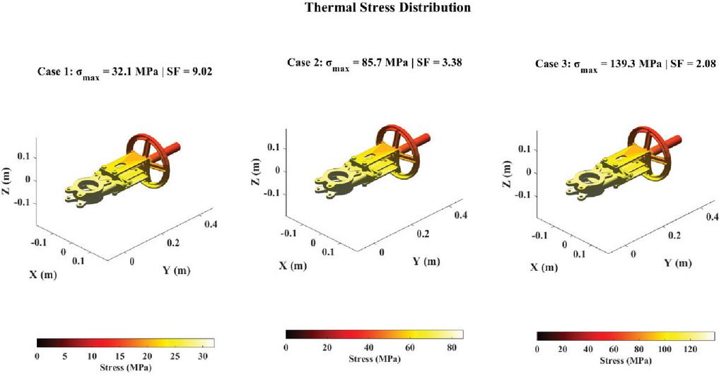
Figure 3 Thermal stress distribution for Case 1 to Case 3. Stress increases with temperature, with concentrations in constrained regions.
Figure 3 presents the thermal stress distribution of the knife gate valve at various cases of increasing temperature and the stress level increases gradually in the entire body of the valve. Case 3 has much higher stress than Case 1 and a corresponding smaller safety factor because of the decrease in material strength with temperature. Stress concentration mainly occurs in load bearing and constrained areas which implies critical areas that are vulnerable to the structural hazard of thermal origin.
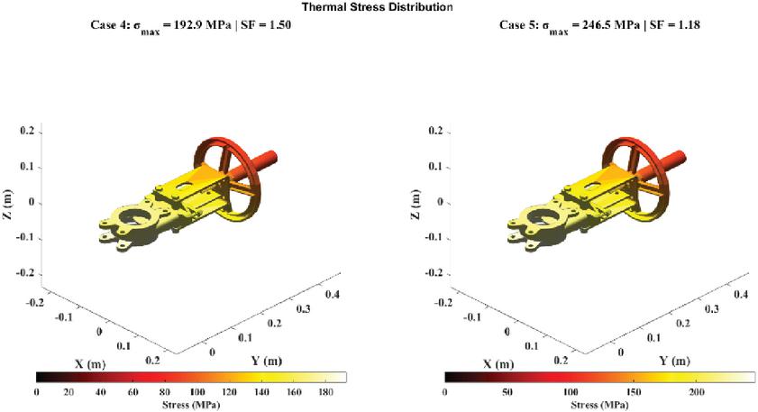
Figure 4 Thermal stress distribution for Case 4 and Case 5. Case 5 shows the highest stress and a critical safety factor of 0.95.
Figure 4 illustrates the distribution of the thermal stress of Case 4 and Case 5 of the valve. Each case has the maximum stress and the corresponding safety factor, where it is clear that Case 5 is close to the material limit with MPa and . The color contours show the area with the greatest thermal stress that is the area with potential structural concern in extreme operating temperatures. The spatial distribution of thermo-mechanical stress strongly influences knife gate valve reliability at elevated temperatures. High-stress regions occur mainly near load-bearing and geometrically constrained areas, where restricted thermal expansion combines with pressure loading to intensify local stresses. From Case 1 to Case 5, maximum von Mises stress increases from 32.15 MPa to 246.45 MPa, while temperature-dependent yield strength decreases, causing the safety factor to decline progressively. These localized regions may experience yielding or excessive deformation before the entire valve becomes critical. Such deformation can reduce gate clearance, increase actuation resistance, and impair sealing performance. In Case 5, stress exceeds yield strength, producing a safety factor of 0.95 and indicating critical structural reliability.
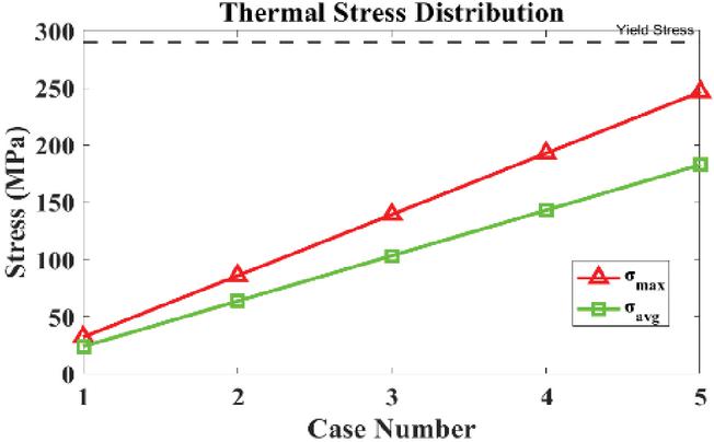
Figure 5 Maximum and average thermal stress. Stress increases progressively with temperature, indicating greater stress localization.
Figure 5 indicates how maximum and average thermal stress in the knife gate valve varies under five operating temperature cases through a Digital Twin-based FEA. Both stress measures increase nearly in direct proportion to temperature, which is the cumulative effect of thermal expansion and the effect of temperature on material softening of SS316. The fact that and are becoming more and more different, which is why there is an increased degree of stress localization in the constrained and load-bearing areas of the valve. The higher cases of proximity of to the yield-stress limit indicate the occurrence of thermally induced structural risk at high operating temperatures.
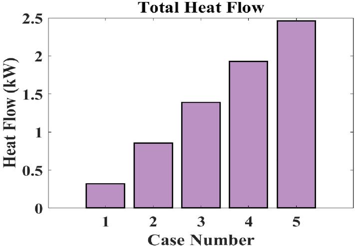
Figure 6 Total heat flow. Heat flow rises monotonically from 0.32 kW to 2.46 kW, driving the corresponding increase in thermal stress across operating cases.
Figure 6 indicates that the total heat flow through the knife gate valve was increasing with successive temperature cases, and the thermal transfer of the heat is higher with the increase in the operating temperature. Increased conduction and convection due to the increased temperature gradients is indicated by the monotonic increase in heat flow. This augmented thermal load has a direct effect of augmented thermal stresses and consequent deterioration of thermo-mechanical performance.
Table 4 Thermal and material properties analysis. Th target operating (hot-side) temperature (∘C); Tmax maximum temperature attained (∘C); Tavg average temperature (∘C); temperature-dependent yield strength (MPa); heat flow rate (kW); percentage reduction in yield strength relative to the room-temperature reference value
| Case | Th (∘C) | Tmax (∘C) | Tavg (∘C) | (MPa) | Q (kW) | (%) |
| 1 | 50 | 44.09 | 37.87 | 282.9 | 0.32 | -2.5% |
| 2 | 100 | 84.25 | 67.64 | 270.9 | 0.86 | -6.6% |
| 3 | 150 | 124.40 | 97.42 | 259.0 | 1.39 | -10.7% |
| 4 | 200 | 164.56 | 127.20 | 247.1 | 1.93 | -14.8% |
| 5 | 250 | 204.72 | 156.97 | 235.2 | 2.46 | -18.9% |
Table 4 shows the thermal behavior and temperature dependent material behavior of the knife gate valve at rising operating temperatures. The findings reveal an increasing trend of the maximum and average temperatures and the rate of heat flow with an increase in thermal load and a steady decrease in the yield strength because of thermal softening. The rising proportion rate of reduction of the yield strength as compared to the reference state demonstrates the high effects of high temperature in material integrity that in turn directly affect the future structural and operational performance.
5.3 Structural Analysis
Structural analysis is used to assess stress, deformation, and safety factor of the knife gate valve when subjected to material behavior that is dependent on temperature. The findings determine the critical operating conditions and areas which are likely to generate and thermomechanical failure with high thermal loads.
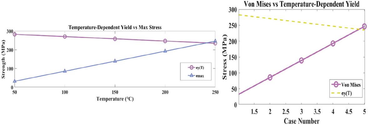
Figure 7 Temperature-dependent yield strength and stress yield strength decreases while induced stress increases with temperature.
Figure 7 illustrates the correlation between temperature-dependent yield strength and maximum induced stress where the higher the temperature, the softer the material but the more the thermal stress the higher. The intersection of these curves at a high temperature means that structural safety margin is reduced. The graph provided indicates the rise of von Mises stress with respect to operating cases compared to the falling yield strength. The intersection direction brings out the direction of yielding and high risk of failure in extreme thermal conditions.
The reduction in temperature-dependent yield strength, rather than an increase in thermal loading alone, is the primary driver of the declining safety margin. As shown in Table 5, the safety factor decreased from 8.80 at Case to 0.95 at Case , while deformation increased correspondingly from 0.107 mm to 0.807 mm. The joint decline in structural safety margin and increase in axial deformation indicates that temperature-dependent material softening and thermal expansion act together to compound the functional risk of the valve at elevated operating temperatures.
Table 5 Structural analysis with temperature-dependent yield. max maximum induced stress (MPa); temperature-dependent yield strength (MPa); SF (Tdep) temperature-dependent safety factor; von Mises von Mises equivalent stress (MPa); Deform axial deformation (mm)
| Case | max (MPa) | (MPa) | SF (Tdep) | von Mises (MPa) | Deform (mm) |
| 1 | 32.15 | 282.9 | 8.80 | 32.15 | 0.107220 |
| 2 | 85.72 | 270.9 | 3.16 | 85.72 | 0.282120 |
| 3 | 139.30 | 259.0 | 1.86 | 139.30 | 0.457020 |
| 4 | 192.87 | 247.1 | 1.28 | 192.87 | 0.631920 |
| 5 | 246.45 | 235.2 | 0.95 | 246.45 | 0.806820 |
The response of the knife gate valve in relation to the rise in temperature was summed up in Table 5 using temperature-dependent material properties. The highest possible stress and von Mises stress increase steadily with operating temperature whereas the yield strength decreases with thermal softening causing a great decrease in safety factor. Case 5 denotes a life-threatening situation in which the safety factor is less than unity and the maximum deformation occurs indicating the development of potential structural failure under the high thermal loading situations.
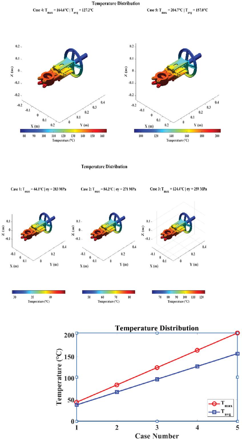
Figure 8 Temperature distribution. 3D contours reveal localized hot spots near the gate and flow-contact areas, with spatial temperature intensity growing across successive cases.
Figure 8 presents the thermal performance of the knife gate valve in terms of 3D temperature contours and a temperature variation curve in various operating scenarios. The contour diagrams show hot spots on locality in areas around the gate and flow-contact areas; this means that there is an imbalanced heat distribution. The more the number of cases, the larger the spatial temperature intensity and affected areas. The line plot presents a quantitative increase in the maximum and average temperature with the increase in thermal load. The combination of these findings proves the existence of progressive thermal accumulation and the importance of this process to thermo-mechanical performance assessment.
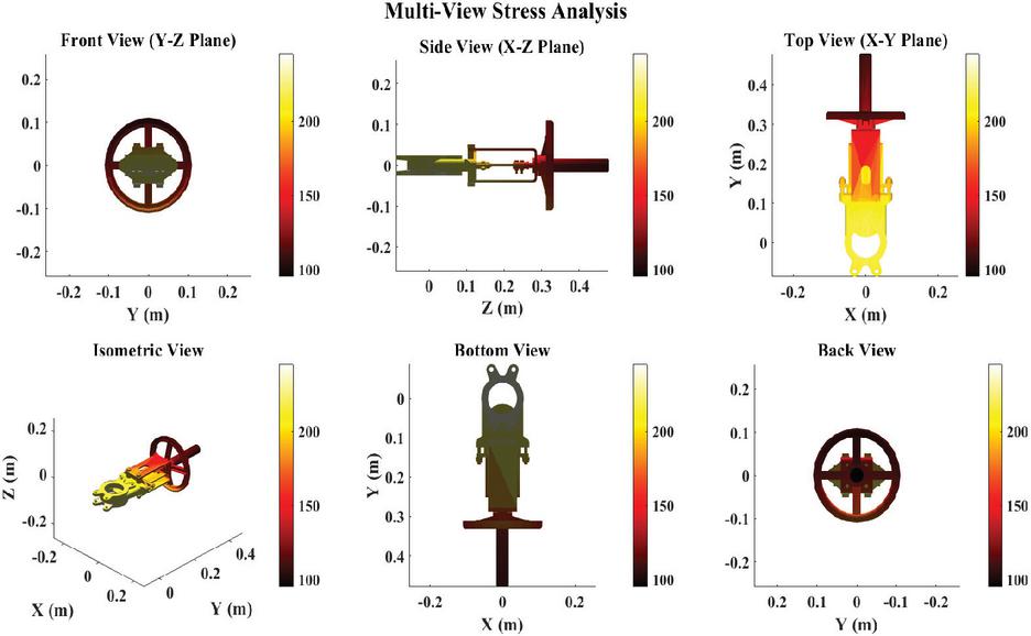
Figure 9 Multi-view stress analysis. Consistent stress concentration near the gate, stem, and junction interfaces across all viewing angles confirms these as the primary zones of structural criticality.
Figure 9 depicts the multi-view stress distribution of the knife gate valve in the operational loading conditions in various geometrical perspectives. The contour plots demonstrate areas of concentration of stress close to the gate, stem, and junction interfaces, which are similar in front, side, top, bottom, and isometric views. This complete visualization proves the areas of criticality in terms of structural integrity and mechanical reliability.
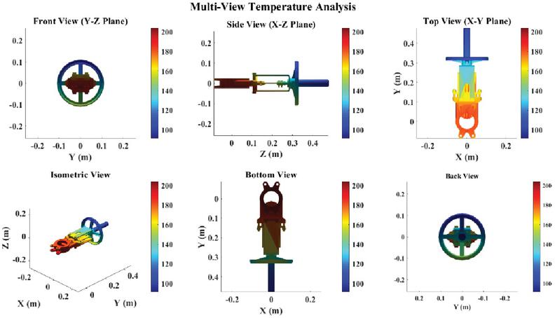
Figure 10 Multi-view temperature analysis. Uniform thermal gradients across all views confirm consistent heat dissipation behavior, with higher temperatures concentrated along the gate and flow-interaction regions.
Figure 10 illustrates the temperature distribution of the knife gate valve in a multi-view under thermal loading conditions based on various geometrical views. The color contours show that the areas of higher temperatures are along the gate and areas of flow-interaction, whereas the cooler areas are along the stem and outer housing. The uniformity of the shape in the front, side, top, bottom, and isometric position proves that the thermal gradient is the same and the behavior of heat dissipation is constant.
The variation of yield strength with operating temperature is an important factor governing the structural reliability of the knife gate valve under thermal loading. The temperature-dependent yield strength of SS316 decreases progressively from 282.9 MPa at Case to 235.2 MPa at Case , corresponding to an 18.9% reduction relative to the reference yield strength of 290 MPa. This reduction follows the linear temperature-dependent softening relation, indicating a progressive reduction in the available material strength margin as thermal exposure increases. The structural significance of this trend becomes evident when the temperature-dependent yield strength is evaluated together with the predicted maximum von Mises stress, as summarized in Table 6.
Table 6 Yield strength degradation and structural reliability margin across operating cases. Tavg=average operating temperature (∘C); temperature-dependent yield strength (MPa); maximum induced stress (MPa); SF () safety factor, defined as the ratio of temperature-dependent yield strength to maximum induced stress; y vs. Ref. percentage reduction in yield strength relative to the room-temperature reference value (290 MPa); Reliability Status qualitative structural safety classification derived from the safety factor value (Safe/Marginal/Critical)
| Tavg | y(T) | max | SF | y vs. | ||
| Case | (∘C) | (MPa) | (MPa) | (y/max) | Ref. (%) | Reliability Status |
| 1 | 37.87 | 282.9 | 32.15 | 8.80 | -2.5% | Safe (high margin) |
| 2 | 67.64 | 270.9 | 85.72 | 3.16 | -6.6% | Safe |
| 3 | 97.42 | 259.0 | 139.30 | 1.86 | -10.7% | Safe (reducing margin) |
| 4 | 127.20 | 247.1 | 192.87 | 1.28 | -14.8% | Marginal |
| 5 | 156.97 | 235.2 | 246.45 | 0.95 | -18.9% | Critical (SF 1) |
The maximum predicted stress increases substantially from 32.15 MPa at Case 1 to 246.45 MPa at Case 5, while the safety factor decreases from 8.80 to 0.95 due to simultaneous temperature-induced material softening. Between Case 4 and Case 5, the safety factor crosses below unity, with linear interpolation indicating an approximate critical temperature range of 240–245∘C for the adopted material model. This threshold is considered an indicative condition-monitoring limit rather than an experimental failure temperature. The results demonstrate that incorporating temperature-dependent yield strength is essential for reliable structural assessment, as neglecting material softening may overestimate safety margins at elevated temperatures.
5.4 Digital Twin Evaluation
Analysis of the health status of the knife gate valve under increasing temperatures and its risk is evaluated by comparing the essential indicators of the valve, such as the torque, the seal pressure, and the remaining useful life. The shift under normal to warning condition is recorded, which shows the effects of thermal loading on the performance of the valve.
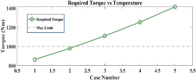
Figure 11 Required torque vs temperature. Torque rises from 864.5 Nm to 1414.6 Nm, exceeding the safe operating limit at Case 5.
Figure 11 presents the dependence on the number of the case and the required torque with an increase in temperature. The graph shows that the required torque was increasing linearly as a result of an increase in temperature, and the values of the torque neared the maximum limit as temperature increased. Case 5 has surpassed the maximum torque limit indicating that there may be an issue with operation.
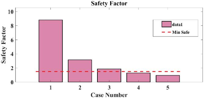
Figure 12 Safety factor declines from 8.80 to 0.95, falling below the minimum acceptable threshold (red dashed line) at Case 5.
Figure 12 provides the safety factor of each case, which shows a strong reduction in the safety with the increase in temperature. The lower limit of the safety factor is shown by the red dashed line. In Case 1, the safety factor is much higher than the minimum whereas in Case 5, it is lower than the limit of the acceptable level, which means that it is riskier. The graph shows the declining structural reliability with increase in operating temperature.
Table 7 Operating metrics and Digital Twin status. Torque required actuator torque (Nm); Seal seal contact pressure (MPa); Health valve health score (%); RUL Remaining Useful Life (years); Torque/Seal/Stress Alert binary Digital Twin fault-flag indicators (yes/no) based on threshold exceedance; Status overall Digital Twin condition classification (NORMAL/WARNING)
| Torque | Seal | Health | RUL | Torque | Seal | Stress | ||
| Case | (Nm) | (MPa) | (%) | (Years) | Alert | Alert | Alert | Status |
| 1 | 864.5 | 1.183 | 100.0 | 74.57 | no | no | no | NORMAL |
| 2 | 981.0 | 1.154 | 100.0 | 51.30 | no | no | no | NORMAL |
| 3 | 1110.3 | 1.126 | 75.0 | 38.27 | yes | no | no | NORMAL |
| 4 | 1254.0 | 1.097 | 75.0 | 29.93 | yes | no | no | NORMAL |
| 5 | 1414.6 | 1.069 | 55.0 | 24.14 | yes | no | yes | WARNING |
Table 7 displays the operation health and risk assessment of the knife gate valve with the Digital Twin in increasing temperature conditions. The table has a correlation between actuator torque, seal pressure, health score, and remaining useful life and alert status of torque, seal, and stress limits. The gradual deterioration and state of normal operation to warning state can be easily noticed as the thermal loading progresses in Case 1 to Case 5.
Seal pressure is an important indicator of valve sealing performance under elevated-temperature operation. In the Digital Twin framework, the temperature-dependent seal pressure is monitored across the five operating cases to assess progressive sealing degradation and associated leakage risk. As temperature increases, thermal expansion of the valve components and reduced elastic recovery of the EPDM sealing material contribute to a gradual reduction in effective seal contact pressure. Therefore, Table 8 presents the case-wise seal pressure, percentage reduction from the baseline condition, Digital Twin seal-alert status, and corresponding model-based leakage-risk classification.
Table 8 Seal pressure degradation and leakage-risk assessment across operating cases. Tavg average operating temperature (∘C); Seal Pressure effective seal contact pressure at the gate-seat interface (MPa); Reduction vs. Baseline percentage decrease in seal pressure relative to the Case 1 reference value; Seal Alert (DT) Digital Twin binary fault-flag indicator (Yes/No) triggered when seal pressure falls below the defined safe threshold; Leakage-Risk Level qualitative risk classification (Low/Low-Moderate/Moderate/Moderate-High/High) derived from the seal pressure trend and its proximity to the alert threshold
| Tavg | Seal | Reduction vs. | Seal | Leakage-Risk | |
| Case | (∘C) | Pressure (MPa) | Baseline (%) | Alert (DT) | Level |
| 1 | 37.87 | 1.183 | 0.0 | No | Low |
| 2 | 67.64 | 1.154 | 2.5 | No | Low |
| 3 | 97.42 | 1.126 | 4.8 | No | Low-Moderate |
| 4 | 127.20 | 1.097 | 7.3 | No | Moderate |
| 5 | 156.97 | 1.069 | 9.6 | No | Moderate-High |
Table 8 shows a consistent decline in seal pressure from 1.183 MPa in Case 1 to 1.069 MPa in Case 5, representing a 9.6% reduction relative to the baseline. Although the Digital Twin seal alert remains inactive throughout the evaluated cases, the continuous reduction indicates progressively increasing sealing risk with temperature. In Case 5, reduced seal pressure occurs together with 0.80682 mm deformation and an active stress alert, indicating combined structural and sealing deterioration.
5.5 Critical Case Analysis (Case 1 to Case 5)
Case-wise analysis is the summary of thermal, structural, and operational behavior of the knife gate valve with the gradually increasing temperature conditions. The findings suggest increasing thermal loads and stress rates and declining safety margins, which point to the situation when operating stability at high temperatures is increasingly limited.
Table 9 Summary of thermal, structural, and operational results (Case 1 to Case 5). Th target hot-side temperature; temperature rise from reference (30∘C, 80∘C, etc.); Tmax/Tavg maximum/average attained temperature (∘C); y(avg temp) yield strength at average temperature (MPa); max/avg maximum/average induced stress (MPa); SF safety factor; Deformation axial displacement (m); Torque required actuator torque (Nm); Seal Pressure seal contact pressure (MPa)
| Case | Condition | Thermal Results | Heat Flow | Yield Strength | Stress Results | Structural Results | Operational Results |
| Case 1 | C, C | C C | 0.32 kW | MPa (Temperature-Dependent) | MPa MPa SF=8.80 | Von Mises 32.15 MPa Deformation 0.000107 m | Torque 864.48 Nm Seal Pressure 1.183 MPa |
| Case 2 | C, C | C C | 0.86 kW | MPa (Temperature-Dependent) | MPa MPa SF 3.16 | Von Mises 85.72 MPa Deformation 0.000282 m | Torque 981.02 Nm Seal Pressure 1.154 MPa |
| Case 3 | C, C | C C | 1.39 kW | MPa (Temperature-Dependent) | MPa MPa SF 1.86 | Von Mises 139.30 MPa Deformation 0.000457 m | Torque 1110.26 Nm Seal Pressure 1.126 MPa |
| Case 4 | C, C | C C | 1.93 kW | MPa (Temperature-Dependent) | MPa MPa SF 1.28 | Von Mises 192.87 MPa Deformation 0.000632 m | Torque 1254.04 Nm Seal Pressure 1.097 MPa |
| Case 5 | C, C | C C | 2.46 kW | MPa (Temperature-Dependent) | MPa MPa SF 0.95 | Von Mises 246.45 MPa Deformation 0.000807 m | Torque 1414.56 Nm Seal Pressure 1.069 MPa |
Table 9 presents a comprehensive case-wise summary of the thermo-mechanical and operational response of the knife gate valve under progressive temperature rise from 50∘C to 250∘C. The findings have shown that there is a definite rising trend in maximum and mean temperatures, heat flow, and stresses caused by temperature and the decrease in the strength of yield and safety factor with temperature. The rates of structural deformation and von Mises stress gradual grow with temperature contributing to high actuator torque requirement and progressive decline of seal pressure, which points to high potential of functional deterioration and the development of unsafe operating conditions as thermal load intensifies.
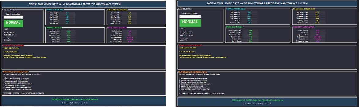
Figure 13 Digital Twin operational monitoring and predictive maintenance system (Case 1 and Case 2). Case 1 shows stable NORMAL status, while Case 2 begins triggering alerts on actuator health and torque, signaling early performance deviation.
As Figure 13 displays, the Digital Twin of the knife gate valve is being monitored in two operation conditions. Case 1 shows the valve in its normal work, and the indicators are all in green, which means stable operation. Case 2, however, has alerts in numerous parameters of operation, including actuator health and actuator torque, which points to the transition towards the abnormal maintenance conditions and, thus, the possibility of closer monitoring and possible maintenance. The system offers useful indications as to the performance of the valve such as the health scores, torque, and the pressure that is vital in terms of predictive maintenance.
The Digital Twin operational monitoring system of the knife gate valve in Case 3 and Case 4 is illustrated in Figure 14. In Case 3, the valve is yet operating within the normal range with all indicators indicating green meaning that it is in a stable state of operation. In Case 4, however, some alerts have been activated, especially on the state of actuators and the torque, which points to the fact that the valve is nearing some critical conditions. The system gives live feedback on different operational parameters and this gives information that is important in predictive maintenance as well as taking timely action to avert failures.
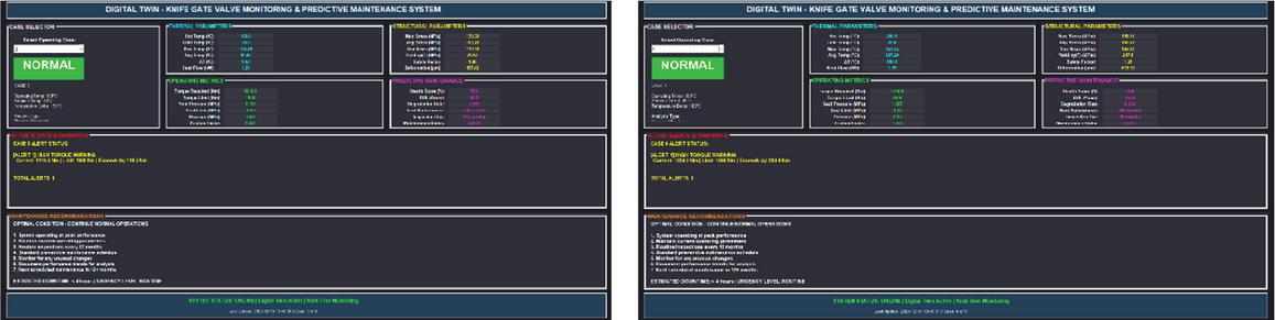
Figure 14 Digital Twin monitoring for Case 3 and Case 4. Case 3 remains NORMAL, but Case 4 activates torque and actuator alerts, indicating the valve is approaching critical operating conditions.
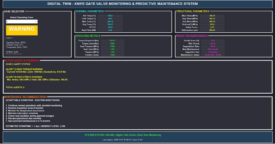
Figure 15 Digital Twin monitoring for Case 5-knife gate valve performance. The dashboard reports a WARNING status as maximum stress (246.5 MPa), torque, and reduced seal pressure jointly indicate elevated failure risk and reduced remaining useful life.
In Figure 15, the Digital Twin monitoring system of Case 5 of a knife gate valve, the system also reports that the status is a “WARNING” state. The thermal parameters are found to be high, and the highest stress was 246.5 MPa which is above the acceptable range. There are also alarming values of the operational parameters, such as torque and pressure. The levels of structural parameters are also critical like stress and deformation. The health score and remaining useful life are significantly lesser in the predictive maintenance section, which shows that there might be risks of failure. The system has raised several alerts, particularly on high-torque and stress and advises on regular monitoring and possible maintenance procedures to avoid failure.
5.6 Discussion
The discussion has pointed out an all-encompassing thermo-mechanical analysis of a knife gate valve given the high temperature conditions by combining thermal analysis, structural response, and operational performance into a Digital Twin system. The findings reveal an effect of temperature increase to material softening, increase in stress, increase in deformation, and decrease in safety margins in addition to the effect on actuator torque demand and sealing reliability. The thermal structural cross coupling offers a realistic view of working behavior allowing the early determination of the critical temperatures, the stress concentration regions, and functional risks that would not be easily detected with only mechanical or isothermal assumptions.
In comparison to multiphysics investigation of thermally induced performance drift in servo valves reported by [29] that concentrated on displacement and pressure variations based on the transfer-function-based modeling, the present study expands the analysis by incorporating full-field thermo-mechanical finite element outputs into a Digital Twin model of a knife gate valve. The method allows evaluating stress, deformation, safety factor, actuator torque, and sealing degradation all at the same time with temperature dependent material behavior. Therefore, the suggested framework provides a more comprehensive and valve-centric performance and risk assessment capability and is therefore more useful in forecasting structural safety and operational reliability when operating in high-temperature industry environments. Temperature-dependent material softening significantly influences the thermo-mechanical performance and operational reliability of the knife gate valve. As temperature increases, yield strength decreases, reducing the material’s resistance to combined thermal and mechanical stresses. In the present study, yield strength decreases from 282.9 MPa in Case 1 to 235.2 MPa in Case 5, while maximum von Mises stress increases correspondingly from 32.15 MPa to 246.45 MPa. Consequently, the safety factor decreases sharply from 8.80 to 0.95. These results demonstrate that assuming constant room-temperature material properties would significantly overestimate structural safety at elevated operating temperatures. Therefore, explicitly accounting for material softening is essential for accurately predicting yielding, deformation, actuation resistance, sealing deterioration, and safe operating limits under high-temperature service conditions.
5.6.1 Limitation
• Temperature-Dependent Yield Strength Assumption: The safety analysis is based on the assumption of a temperature-dependent model of yield strength of SS316 which might not take into account all material variations or possible factors of degradation. This assumption restricts the applicability of the findings to other materials or on the extremes of temperatures not discussed in the research.
• Simplified Operational Conditions: The conditions of operation are assumed to be steady, the paper does not look at the dynamic variation of the operational conditions of the valve e.g. quick change in pressure, temperature, or load. In practice, more complicated scenarios might occur, which might impact the validity of the Digital Twin model and the predictive maintenance results.
6 Conclusion
This study presents a comprehensive analysis of a knife gate valve in different thermal conditions is given with the consideration of thermal stress distribution, performance, and reliability in operation. Yield strength of the SS316 material of various temperature conditions was integrated to evaluate the safety factor of varying thermal loads. The model of a Digital Twin was created in order to track the most essential parameters, including actuator torque, seal pressure, and stress, to anticipate possible failures. The health of the valve, the remaining useful life as well as the critical operation metrics were studied under five temperature conditions showing the shift between normal use conditions to warning conditions with the rise of thermal loads. The findings offered useful information on predictive maintenance and structural integrity evaluations to make sure that the valve does not operate out of the safety range when the conditions are different.
Although developed and validated for a knife gate valve, the underlying methodology is not limited to this component. The integration of temperature-dependent material behavior with coupled thermal-structural FEA within a Digital Twin architecture is generalizable to other valve types, such as ball, gate, and control valves, subjected to thermal cycling in process industries. Beyond valves, the framework could extend to other thermally loaded components with critical sealing or load-bearing interfaces, including pipeline flanges, heat exchangers, and pressure vessel fittings. Such extensions would primarily require recalibrating component-specific geometry, material properties, and operational thresholds, while retaining the same thermal-structural coupling and Digital Twin monitoring logic, broadening applicability as a predictive maintenance tool.
Declaration
Data Availability
Data are available from the corresponding author upon reasonable request.
Conflicts of Interest
The authors declare no conflicts of interest.
Funding Statement
Research on the Construction Method of Digital Twin Mechanism Model for Power Transmission and Transformation Equipment Based on Domestic Finite Element Analysis Software (Project Number: 066700KC2311 0042).
Author Contribution
Long Na: Conceptualization, methodology, simulation, analysis, and writing. Gan Rundong: Supervision, validation, review, and editing. All authors approved the final manuscript.
Ethical Approval
Not applicable.
Consent to Participate
Not applicable.
Consent to Publication
Not applicable.
Competing Interests
The authors declare no competing interests.
References
[1] H. Elsherbiny, L. Szamel, M. K. Ahmed, and M. A. Elwany, “High Accuracy Modeling of Permanent Magnet Synchronous Motors Using Finite Element Analysis,” Mathematics, vol. 10, no. 20, p. 3880, 2022, doi: 10.3390/math10203880.
[2] C. Song, H. Chang, D. Zhang, Y. Zhang, M. Shi, and X. Meng, “Biomechanical Evaluation of Oblique Lumbar Interbody Fusion with Various Fixation Options: A Finite Element Analysis,” Orthopedic Surgery, vol. 13, no. 2, pp. 517–529, 2021, doi: 10.1111/os.12877.
[3] L. Comuzzi et al., “Crestal and Subcrestal Placement of Morse Cone Implant–Abutment Connection Implants: An In Vitro Finite Element Analysis (FEA) Study,” Biomedicines, vol. 11, no. 11, p. 3077, 2023, doi: 10.3390/biomedicines11113077.
[4] P. Van Vinh and L. Q. Huy, “Finite Element Analysis of Functionally Graded Sandwich Plates with Porosity via a New Hyperbolic Shear Deformation Theory,” Defence Technology, vol. 18, no. 3, pp. 490–508, 2022, doi: 10.1016/j.dt.2021.03.006.
[5] G. M. Hekal, M. I. Salama, G. Elsamak, and A. H. Almaadawy, “Shear Behavior of RC Beams Strengthened with Ultra-High-Performance Fiber-Reinforced Concrete Using Finite-Element Analysis,” Asian Journal of Civil Engineering, vol. 24, no. 1, pp. 71–91, 2023, doi: 10.1007/s42107-022-00489-x.
[6] A. F. Schrunder, S. Rodriguez, and A. Rusu, “A Finite Element Analysis and Circuit Modelling Methodology for Studying Electrical Impedance Myography of Human Limbs,” IEEE Transactions on Biomedical Engineering, vol. 69, no. 1, pp. 244–255, 2022, doi: 10.1109/TBME.2021.3091884.
[7] S. Chhetri and P. Deb, “Finite Element Analysis of Geogrid-Incorporated Flexible Pavement with Soft Subgrade,” Applied Sciences, vol. 14, no. 13, p. 5798, 2024, doi: 10.3390/app14135798.
[8] B. Deon et al., “Digital Twin and Machine Learning for Decision Support in Thermal Power Plant with Combustion Engines,” Knowl.-Based Syst., vol. 253, p. 109578, Oct. 2022, doi: 10.1016/j.knosys.2022.10 9578.
[9] A. Koesters, F. Koetz, M. Bock, M. Fett, R. Breimann, and E. Kirchner, “Methodical Development of a Digital Twin for an Industry Valve,” Machines, vol. 12, no. 10, p. 674, Oct. 2024, doi: 10.3390/machines12100674.
[10] R. Cabrera-Escobar et al., “Finite Element Analysis Method Design and Simulation of Fins for Cooling a Monocrystalline Photovoltaic Panel,” Clean Technologies, vol. 6, no. 2, pp. 767–783, 2024, doi: 10.3390/cleantechnol6020039.
[11] B. Jeon, M.-S. Kim, S.-H. Choi, and Y. Jeong, “Finite Element Analysis Using Elasto-Visco-Plastic Self-Consistent Polycrystal Model for E-form Mg Sheet Subjected to Bending,” Journal of Magnesium and Alloys, vol. 11, no. 4, pp. 1393–1407, 2023, doi: 10.1016/j.jma.2022.10.017.
[12] C. Hernandez, J. Lara, M. A. Arjona, and E. Melgoza-Vazquez, “Multi-Objective Electromagnetic Design Optimization of a Power Transformer Using 3D Finite Element Analysis, Response Surface Methodology, and NSGA-III,” Energies, vol. 16, no. 5, p. 2248, 2023, doi: 10.3390/en16052248.
[13] J.-H. Lee, H. Y. Jang, and S. Y. Lee, “Finite Element Analysis of Dental Implants with Zirconia Crown Restorations,” Materials, vol. 14, no. 10, p. 2666, 2021, doi: 10.3390/ma14102666.
[14] H. D. Kweon, J. W. Kim, O. Song, and D. Oh, “Determination of True Stress-Strain Curve of Type 304 and 316 Stainless Steels Using a Typical Tensile Test and Finite Element Analysis,” Nuclear Engineering and Technology, vol. 53, no. 2, pp. 647–656, 2021, doi: 10.1016/j.net.2020.07.014.
[15] R. A. Moga et al., “Cortical and Trabecular Bone Stress Assessment during Periodontal Breakdown,” Medicina, vol. 59, no. 8, p. 1462, 2023, doi: 10.3390/medicina59081462.
[16] A. Sur and M. Kanoria, “Thermoelastic Interaction in a Viscoelastic Functionally Graded Half-Space under Three-Phase-Lag Model,” Eur. J. Comput. Mech., vol. 23, no. 5-6, pp. 179–198, Nov. 2014, doi: 10.1080/17797179.2014.978143.
[17] M. Sharifi Guildennoei et al., “Finite Element Analysis of Shear Reinforcing of Reinforced Concrete Beams,” Buildings, vol. 13, no. 4, p. 1034, 2023, doi: 10.3390/buildings13041034.
[18] K. A. Ahmed, L. N. Lowes, and D. E. Lehman, “Investigation of the Behavior of Slender Reinforced Concrete Walls Using Nonlinear Finite Element Analysis,” Resilient Cities and Structures, vol. 2, no. 1, pp. 120–142, 2023, doi: 10.1016/j.rcns.2023.02.010.
[19] J.-F. Zhang et al., “Biomechanical Analysis of Locking Plates for Fixation of Metacarpal Shaft Fractures,” Orthopaedics & Traumatology: Surgery & Research, vol. 108, no. 8, p. 103340, 2022, doi: 10.1016/j.otsr.2022.103340.
[20] B. H. Mills et al., “Design Evaluation of a Next-Generation High-Temperature Particle Receiver,” Energies, vol. 15, no. 5, p. 1657, 2022, doi: 10.3390/en15051657.
[21] P. Piechota et al., “Experimental Determination Influence of Flow Disturbances Behind the Knife Gate Valve,” Sensors, vol. 23, no. 10, p. 4677, 2023, doi: 10.3390/s23104677.
[22] A. Kösters, M. Bock, M. Fett, and R. Breimann, “Methodical Development of a Digital Twin for an Industry Valve,” Machines, vol. 12, no. 10, p. 674, 2024, doi: 10.3390/machines12100674.
[23] R. Kerkeni, S. Khlif, A. Mhalla, and K. Bouzrara, “Digital Twin Applied to Predictive Maintenance for Industry 4.0,” ASME Journal of Nondestructive Evaluation, vol. 7, no. 4, p. 041008, 2024, doi: 10.1115/1.4065875.
[24] I. Abdullahi, S. Longo, and M. Samie, “Towards a Distributed Digital Twin Framework for Predictive Maintenance in Industrial Internet of Things (IIoT),” Sensors, vol. 24, no. 8, p. 2663, 2024, doi: 10.3390/s24082663.
[25] N. Abd Wahab et al., “Systematic Review of Predictive Maintenance and Digital Twin Technologies: Challenges, Opportunities, and Best Practices,” PeerJ Computer Science, 2024, doi: 10.7717/peerj-cs.1943.
[26] A. Marra, S. Gerbino, A. Greco, and G. Fabbrocino, “Combining Integrated Informative System and Historical Digital Twin,” Sensors, vol. 21, no. 17, p. 5956, 2021, doi: 10.3390/s21175956.
[27] J. I. Rojas-Sola and J. C. Barranco-Molina, “Study of the Mechanical Behavior of a Single-Cylinder Horizontal Steam Engine,” Applied Sciences, vol. 14, no. 13, p. 5878, 2024, doi: 10.3390/app14135878.
[28] R. Zhang et al., “A Fast Spatio-Temporal Temperature Predictor for Vacuum Assisted Resin Infusion Molding Process,” Journal of Intelligent Manufacturing, vol. 35, no. 4, pp. 1737–1764, 2024, doi: 10.1007/s10845-023-02113-4.
[29] J. Kang, Z. Yuan, and J. Li, “Mechanism Analysis and Evaluation of Thermal Effects on the Operating Point Drift of Servo Valves,” Journal of Zhejiang University-SCIENCE A, vol. 23, no. 4, pp. 286–302, 2022, doi: 10.1631/jzus.A2100464.
[30] J. I. Rojas-Sola and J. C. Barranco-Molina, “Technical Feasibility of a Two-Cylinder Entablature Steam Engine,” Applied Sciences, vol. 14, no. 15, p. 6597, 2024, doi: 10.3390/app14156597.
[31] D. R. Gonzalez-Morales et al., “Mathematical and Physical Modelling of Transient Multi-Phase Flows in a Ladle Shroud during Start-Up,” Processes, vol. 11, no. 6, p. 1628, 2023, doi: 10.3390/pr11061628.
[32] Y. Wang, C. Wang, G. Liu, C. Zhang, and J. Li, “An Assessment Method of Sealing Performance and Stress Intensity Factors at Crack Tip of Subsea Connector Metal Sealing Rings,” Energies, vol. 15, no. 13, p. 4680, 2022, doi: 10.3390/en15134680.
[33] G. S. Lewis, D. Mischler, H. Wee, J. S. Reid, and P. Varga, “Finite Element Analysis of Fracture Fixation,” Current Osteoporosis Reports, vol. 19, no. 4, pp. 403–416, 2021, doi: 10.1007/s11914-021-00690-y.
[34] N. Kardani, A. Zhou, M. Nazem, and S.-L. Shen, “Improved Prediction of Slope Stability Using a Hybrid Stacking Ensemble Method,” Journal of Rock Mechanics and Geotechnical Engineering, vol. 13, no. 1, pp. 188–201, 2021, doi: 10.1016/j.jrmge.2020.05.011.
[35] K. Wang, A. Wang, L. Wu, and G. Xie, “Machine Tool Wear Prediction Technology Based on Multi-Sensor Information Fusion,” Sensors, vol. 24, no. 8, p. 2652, 2024, doi: 10.3390/s24082652.
[36] J. I. Rojas-Sola and J. F. Gutiérrez-Antúnez, “Analysis of the Design of Henry Muncaster’s Two-Cylinder Compound Vertical Steam Engine with Speed Control,” Applied Sciences, vol. 13, no. 16, p. 9150, 2023, doi: 10.3390/app13169150.
[37] M. Marin, A. Hobiny, and I. Abbas, “Finite Element Analysis of Nonlinear Bioheat Model in Skin Tissue Due to External Thermal Sources,” Mathematics, vol. 9, no. 13, p. 1459, 2021, doi: 10.3390/math9131459.
[38] K. Gholami, F. Ege, and R. Barzegar, “Prediction of Composite Mechanical Properties: Integration of Deep Neural Network Methods and Finite Element Analysis,” Journal of Composites Science, vol. 7, no. 2, p. 54, 2023, doi: 10.3390/jcs7020054.
[39] Béné Inox, 458481-80 Knife Gate Valve (CF8M Stainless Steel Body, 316 Stainless Steel Gate, EPDM Seat). Accessed: Dec. 27, 2025. [Online]. Available: https://www.3dfindit.com/en/digitaltwin/knife-gate-valvecf8m-stainless-steel-body316-stainless-steel-gateepdm-seat?path=bene_inox_raccords\%2Findustrie\%2F58_robinetterie\%2F03_vannes_guillotine\%2F58481.prj.
Biographies

Long Na, female, Han ethnicity, born in September 1985, from Guiyang, Guizhou, China, holds a postgraduate degree, and is a Senior Engineer at the Digital Intelligence Operations Center of Guizhou Power Grid Co. Ltd. Her research focuses on information technology.

Gan Rundong, male, Han ethnicity, born in April 1988, from Linshui, Sichuan, China, holds a master’s degree, and is a Senior Engineer at the Digital Intelligence Operations Center of Guizhou Power Grid Co. Ltd. His research focuses on information technology.
European Journal of Computational Mechanics, Vol. 35_2, 103–144
doi: 10.13052/ejcm2642-2085.3522
© 2026 River Publishers