Fracture Prediction Based on Evaluation of Initial Porosity Induced By Direct Energy Deposition
Roya Darabi1, 2, Erfan Azinpour1, 2, Jose Cesar de Sa1, 2, Margarida Machado2, Ana Rosanete Reis1, 2, Josef Hodek3 and Jan Dzugan3
1Institute of Science and Innovation in Mechanical and Industrial Engineering (INEGI), FEUP campus, Rua Dr. Roberto Frias, 400, 4200-465, Porto, Portugal
2Faculty of Engineering of University of Porto (FEUP), Rua Dr. Roberto Frias, 4200-465, Porto, Portugal
3COMTES FHT a.s., Průmyslova 995, 334 41, Dobrany, Czech Republic
E-mail: rdarabi@inegi.up.pt
*Corresponding Author
Received 23 October 2020; Accepted 14 November 2020; Publication 09 January 2021
Abstract
Additive manufacturing (AM) of metals proved to be beneficial in many industrial and non-industrial areas due to its low material waste and fast stacking speed to fabricate high performance products. The present contribution addresses several known challenges including mechanical behaviour and porosity analysis on directed energy deposition (DED) manufactured stainless steel 316L components. The experimental methodology consisting of metal deposition procedure, hardness testing and fractographic observations on manufactured mini-tensile test samples is described. A ductile fracture material model based on the Rousselier damage criterion is utilized within a FE framework for evaluation of material global response and determination of initial porosity value representing the structure’s nucleating void population. Alternatively, the initial pore sizes are characterized using the generalized mixture rule (GMR) analysis and the validity of the approach is examined against the experimental results.
Keywords: Directed energy deposition (DED), additive manufacturing (AM), porosity, mechanical behavior, initiation and propagation of cracks.
1 Introduction
Metal additive manufacturing (AM) has grown rapidly over the past decade to become a transformative technology capable of revolutionizing the way in which goods from diverse industrial sectors, such as biomedical, aerospace, automotive, marine and offshore, are produced. AM technologies could manufacture parts with intricate configurations, hybrid structures and composites with reduced raw material waste, which could be impossible to attain with conventional manufacturing processes. AM, also popularly known as metal three-dimensional (3D) printing, refers to various innovative processes that are used to manufacture three-dimensional products through joining metallic materials including powder, wire, or sheet forms to make objects from CAD models in a layer-by-layer manner [1–4]. This process involves heating, melting and solidification of an alloy by a moving heat source in a layer by layer manner. Due to the repeated heating and cooling stages, the part usually undergoes several melting and solidification cycles which affect the microstructure and the mechanical behavior of the material [4]. Based on ASTM standard F2792 [5], AM is categorized into powder bed fusion (PBF) and directed energy deposition (DED). The former method is widely being applied due to its advantages in achieving near net shape and final precise dimensions, while the DED technology has high productivity, fast stacking speed and less size restrictions owing to its procedure, in which the metal powder is directly injected and melted to the target location using a heat source [6–9]. Diverse types of this technology can be classified based on the type of the feedstock, in the form of the powder, wire or sheet, and the nature of the heat source, generally being laser beam, electron beam or plasma arc. The present work is focused on the powder-based DED system, which feeds the metal powder into a melt path and utilizes a thermal energy source to create a molten pool into a narrow region, while material is deposited in a layer-wise fashion on a substrate part [10]. The thickness of the deposited layer may vary between 0.1 to a few millimeters [11]. Due to the flexibility to change materials’ compositions at each layer, by simply adjusting feeding materials and process parameters, the possibility of achieving heterogeneous parts is one of the pivotal features of DED processes [10–13]. Antony et al. [14] investigated, experimentally and numerically, the laser melting of SS grade 316L powder on top of a AISI 316L substrate using a pulsed Nd:YAG laser, by focusing on the influence of the laser parameters on the geometry characteristics of melted tracks. They showed that increasing the laser power favors an enhanced energy density of the laser beam, which leads to create larger molten pools, whereas the authors suggested optimum values of scanning speed and laser power for fabricating the single layer sintered tracks. They also developed a FE model for determining the temperature history in the powder melting process. The scanning speed and scanning path were found to be highly influential on mechanical properties and morphology of the fabricated stainless steel parts, respectively in [15] and [16]. Still several challenges need being tackled in DED processes, including limitations in building complex shapes, control of material properties and achieving an efficient powder delivery rate. Due to high thermal gradients during the process, the effect of morphology of structure and final porosity have a significant influence on the mechanical properties and their relation to the laser power, powder flow rate, scan speed and molten pool size should not be ignored [11, 12]. In 2001, Kobryn and Semiatin showed the effect of lack of fusion defects on the anisotropy of mechanical properties of the Ti-6Al-4V deposits, as well as on the the crack initiation spot in the compact tension test results of the samples [17]. Ahmadi et al. [18] investigated the impact of several microstructural properties such as melt pool size, texture orientation and porosity on the mechanical properties of selective laser melting (SLM)-processed 316L stainless steel parts using a finite element model, where they illustrated the influence of controlled parameters such as laser power, scanning velocity and scanning direction on production of components with improved mechanical properties. Wolff et al. [12] studied the anisotropic mechanical behavior of DED-fabricated Ti–6Al–4V components by utilizing X-ray diffraction, fractography and pore analyses, targeting to achieve components with improved mechanical properties. In their study, they highlighted influential factors such as the location of test coupons relative to the surface of the cube component, orientation of the coupons relative to the build and scan direction and laser processing power on the mechanical properties and bulk porosity distribution. To gain higher surface quality, dimensional accuracy and to eliminate the buckling effect, the influence of building direction on the microstructure, mechanical properties and machinability of the 316L stainless steel was studied by Guo et al. [19]. The fabricated 316L stainless steel via SLM process was also studied by Suryawanshi et al. [20] using two different scanning strategies to assess and compare fatigue crack growth, fracture toughness and mechanical properties that could be linked to the porosity content in the SS 316L produced alloys. In this contribution, the impact of the loading direction on the fracture surfaces of tensile samples was shown, where unmelted powder particles were found in the parallel loading direction. In addition, rapid solidification was shown to have notable effect on microstructure, to enhance the yield stress of the processed samples, as well as on developing anisotropic properties. Iqbal et al. [21] conducted mechanical testing on the SS 316L SLM produced components where they demonstrated a link between the reduction in effective cross-sectional area and the presence of un-melted powder particles on the fracture surface of tensile specimens. In [22], the effect of powder recycling and cooling rate was studied on DED manufactured SS 316L samples, while variations of the recorded fracture strain was reported due to the inclusions like oxides in the microstructure of the components, directly influencing the mechanical properties and especially the ductility of the as-deposited components.
Saboori et al. [23, 24] investigated the influence of carrier gas flow rate, shielding gas and type of powder on the porosity and oxide contents of the as-deposited 316L steel, produced with the optimum process parameters. They used the ImageJ software [25] to evaluate the porosity value for an optimized and conventional process. Haoyun Tu et al. [26] studied the fracture behavior of an aluminum laser welded joint (Al 6061) experimentally and numerically, whereby the Rousselier damage model was used for simulation of fracture behavior.
Azinpour et al. studied the fracture in laser-processed 316L stainless steel components process by powder-blown DED technology, with different deposition orientations. The failure induced by growth of micro-cracks and porosities was investigated by using a phase-field ductile fracture model relying on the Rousselier damage criterion [27].
In the present study, as a follow-up to the previous research by the authors, further experimental analyses are conducted on the SS 316L fabricated components to evaluate the material properties of specimens with different anisotropy configurations. The impact of the loading direction and the extraction orientation of miniature-sized test specimens, obtained from a DED fabricated sample part, on the mechanical properties including the ultimate and yield stresses are highlighted. Fracture morphology and porosity evaluations, as well as numerical studies using a ductile fracture model, are conducted to assess crack initiation and propagation in the tensile samples, whereby approximated values of initial porosity are obtained by inverse method. Furthermore, the generalized mixture rule (GMR) method is used to consider the effect of individual pores on the tensile behavior of the specimens. Approximated pore shapes are used to evaluate the bulk porosity volume fraction in three orthogonal orientations. To extract the porosity area of the parts (in percentage), the 2D microscopic surface of one of specimens is employed by ImageJ software, whereby the post processing evaluations suggest that the approximated bulk porosity values using GMR approach are in a close agreement with the calibrated initial porosity values obtained from the ductile fracture model based on Rousselier damage criterion [28, 29].
2 Experimental Procedure
In order to proceed with an experimental campaign miniature tensile specimens were extracted from a cube, with an edge length of 35 mm, of commercially available AISI 316L stainless steel alloy fabricated by directed energy deposition, using a printer InssTek MX600 3D equipped with an Ytterbium fiber laser as the heat source. The manufacturing parameters of the DED procedure are specified in Table 1. Chemical composition and thermo-physical properties of initial powder are given in Tables 2 and 3, respectively.
Table 1 Processing parameters employed in DED process [27]
| Parameters | Value | Unit |
| Laser spot diameter | 0.8 | mm |
| Laser power | 417 | W |
| Scanning speed | 14.166 | mm/s |
| Layer thickness | 0.25 | mm |
| Track overlap | 0.5 | mm |
| Powder feeding rate | 3 | g/s |
Table 2 Chemical Composition of stainless steel 316L powder [27]
| Element | C | Cr | Cu | Mn | Mo | N | Ni | P | S | Si |
| (wt %) | 0.009 | 16.82 | 0.31 | 1.74 | 2.08 | 0.029 | 10.26 | 0.03 | 0.024 | 0.27 |
Table 3 Thermo-physical properties of stainless steel 316L powder [27]
| Parameters | Value | Unit |
| Liquidus temperature | 1723 | K |
| Solidus temperature | 1553 | K |
| Density | 7966 | Kg/m |
| Latent heat | 256400 | J/Kg |
The deposition scheme is shown in Figure 1. After deposition, a total number of 15 miniature size tensile test samples were extracted from the cube in three different orientations with an electrical discharge machine (EDM) technique. For specification of the samples, they are labeled in each direction as and , where as shown in Figure 2.
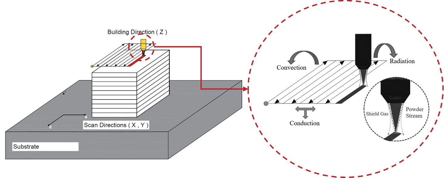
Figure 1 Schematic of the deposition process.
The experimental approach herein follows investigations about the strength and elongation anisotropies in DED-processed SS 316L component coupons and their connection with build orientations, process parameters and the distance of the specimens from the surface of the fabricated component cube due to different temperature gradients of each layer during solidification process [12, 27]. The scheme of the coupon fabrication based on the building direction is depicted in Figure 3, which could be influential in characterization of the tensile properties such as ultimate tensile strength or elongation, as was addressed for instance in [19].
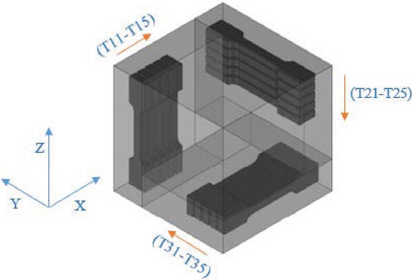
Figure 2 Configuration of the test specimens in regards with the cubic component.

Figure 3 Schematic of the building directions during the fabrication process for (a) sample group and (b) Sample groups and [27].
2.1 Mechanical Testing
The geometry of the miniature tensile samples is shown in Figure 4 and a gauge length of 11 mm is considered. The maximum applied machine load was 5 kN with a constant crosshead velocity of 1 mm/min, at which 15 mini-test samples (five units per configuration) were tested. The setup configuration of the test equipment is depicted in Figure 5. For more precise load measurements, strain gauges or an extensometer were directly fixed to the specimen.
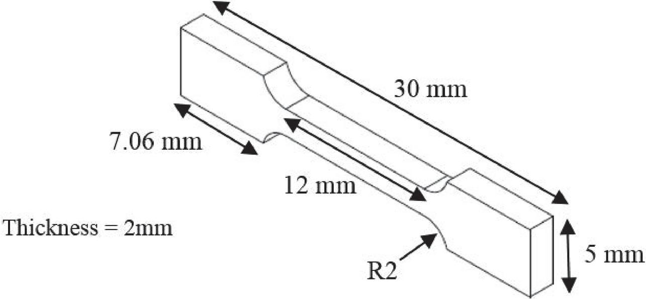
Figure 4 Dimensions of tensile test specimens in mm.

Figure 5 Tensile test setup configuration.
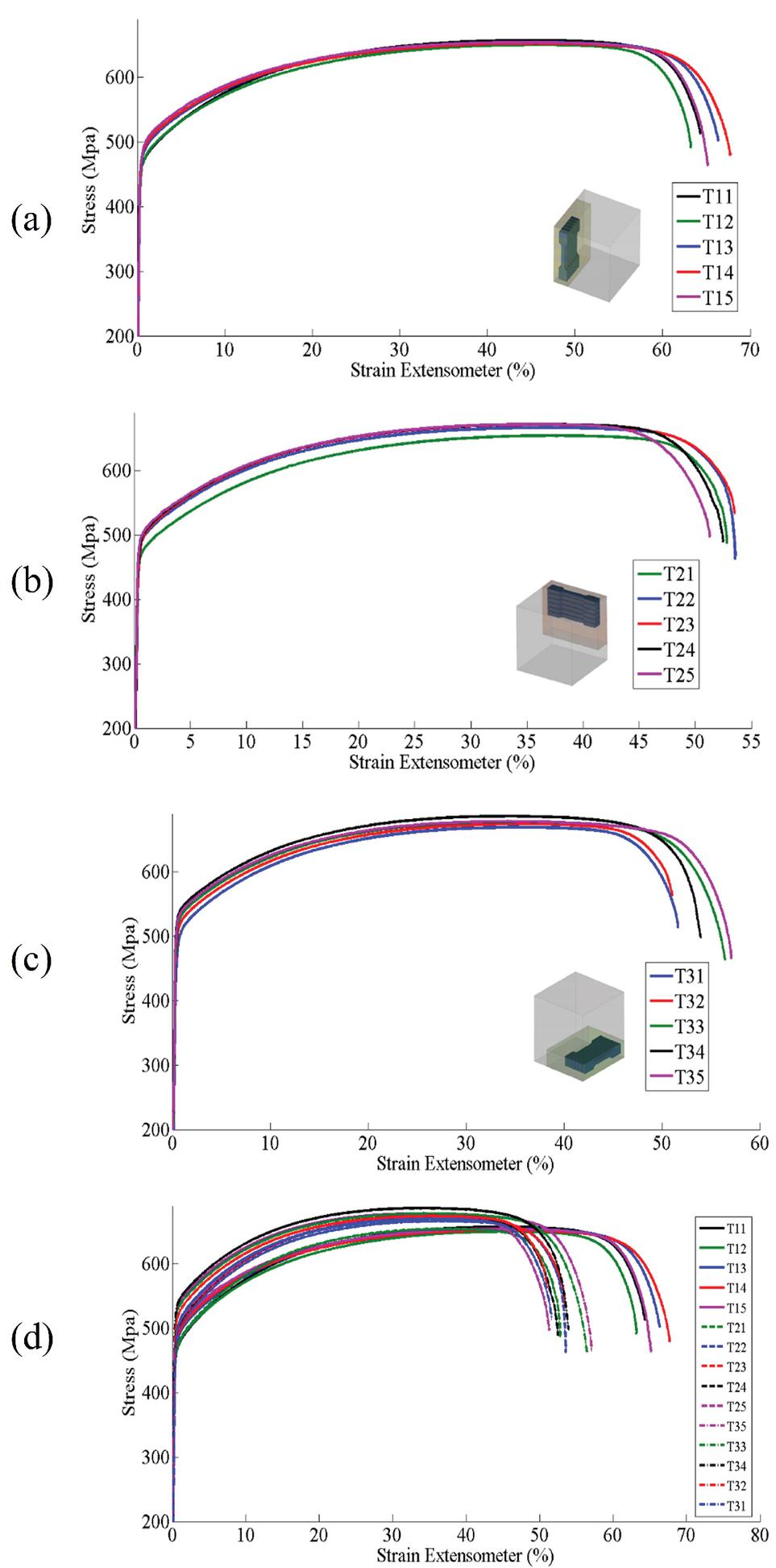
Figure 6 Engineering stress vs. strain curves for samples (a) T11-T15, (b) T21-T25 (c) T31-T35 and (d) all samples.

Figure 7 Yield stress of all samples.
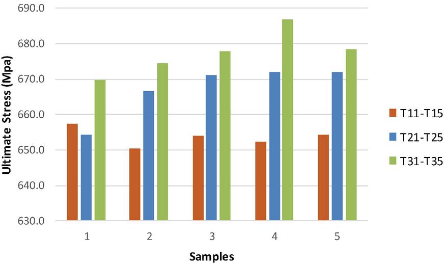
Figure 8 Ultimate tensile strength of all samples.
The anisotropy of mechanical properties of SS 316L SLM-fabricated components was shown in several recent studies, for instance in [15, 16, 19, 20]. In Figure 6(a–d) the stress-strain curves of tensile tests for the different specimens show the influence of the building direction on the mechanical properties. The graphs illustrate that coupons from the YZ plane as displayed in Figure 6(a) have higher ductility than those in the other orientations. The reason may lay on the fact that, as illustrated at Figure 3, the sliced layers in this sample group of specimens, T11-T15, were built perpendicularly to the loading direction, resulting in weaker load-bearing bonding than that of other sample groups. The coupons machined in both XZ-XY directions have greater strength, as shown in Figure 6(b, c), which comes at the cost of smaller failure strain, altogether exhibiting anisotropy in mechanical properties. The variation of the tensile properties including yield and ultimate strength with each sample configuration are shown in the bar graphs of Figures 7 and 8, respectively. Overall, higher yield stress and ultimate tensile strength values are observed for the sample group T31-T35. Although there is no clear uniform pattern of those limit values based on the coupon distance to the component surface, in most cases they grew from surface to interior of the component cube, which can be naturally related to the different cooling rates in terms of the position of the sample within the component. Furthermore, smallest yield limit value is recorded for the coupons close to the exterior of the component in sample groups 2 and 3.
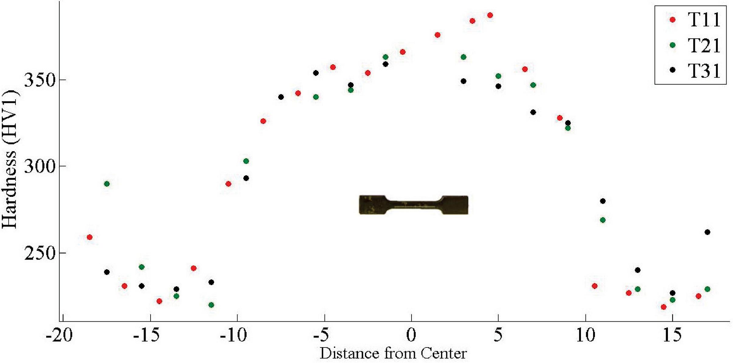
Figure 9 Variation in Vickers micro hardness across the sample heights.
2.2 Hardness and Microstructure
The micro-hardness profile across a tensile sample is shown in Figure 9, revealing variations in different orientations. The hardness slightly increased, near to the center of samples, with average values 301 HV, 294 HV and 293 HV for T11, T21 and for T31, respectively. Compared to what was reported in [21], the fracture location was observed at the higher hardness zones.
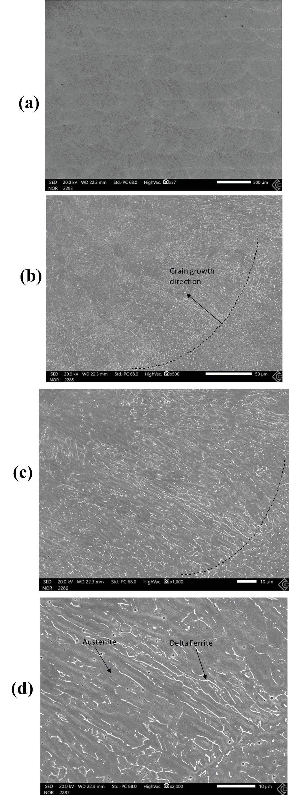
Figure 10 Micrographs of the additive manufactured stainless steels for T31 specimen (a) melt pools overview; (b–d) high magnifications of the microstructure that reveals the grain growth direction and existence of delta ferrites in an austenite matrix.
Figure 10 shows the solidified microstructure in the cross section of the stainless steel fabricated at the building direction for T31. Due to the high delivered energy by the laser beam, a high-temperature gradient between the molten pool and the previously deposited zone is generated, resulting in a directional growth of the dendrites perpendicular to the molten pool border that initiates at the edges and propagates towards the center of the molten pool, as it can be seen in Figure 10(b, c). The presence of residual -ferrite phase could reinforce the austenite base and that could be linked to the higher recorded tensile strength for this sample, while the ductility is comparably lower than the other samples, similar to the observations in [19, 22].
The difference in macro-hardness between the two sections is due to the anisotropy of the dendritic microstructure of the stainless steel. Furthermore, grain coarsening was observed after solidification under low cooling rate, where the alloys solidified within the primary austenite area and also the ferrite phase formed by an eutectic solidification from the remaining melting material between the austenitic dendrites which can be seen in Figure 10(d).
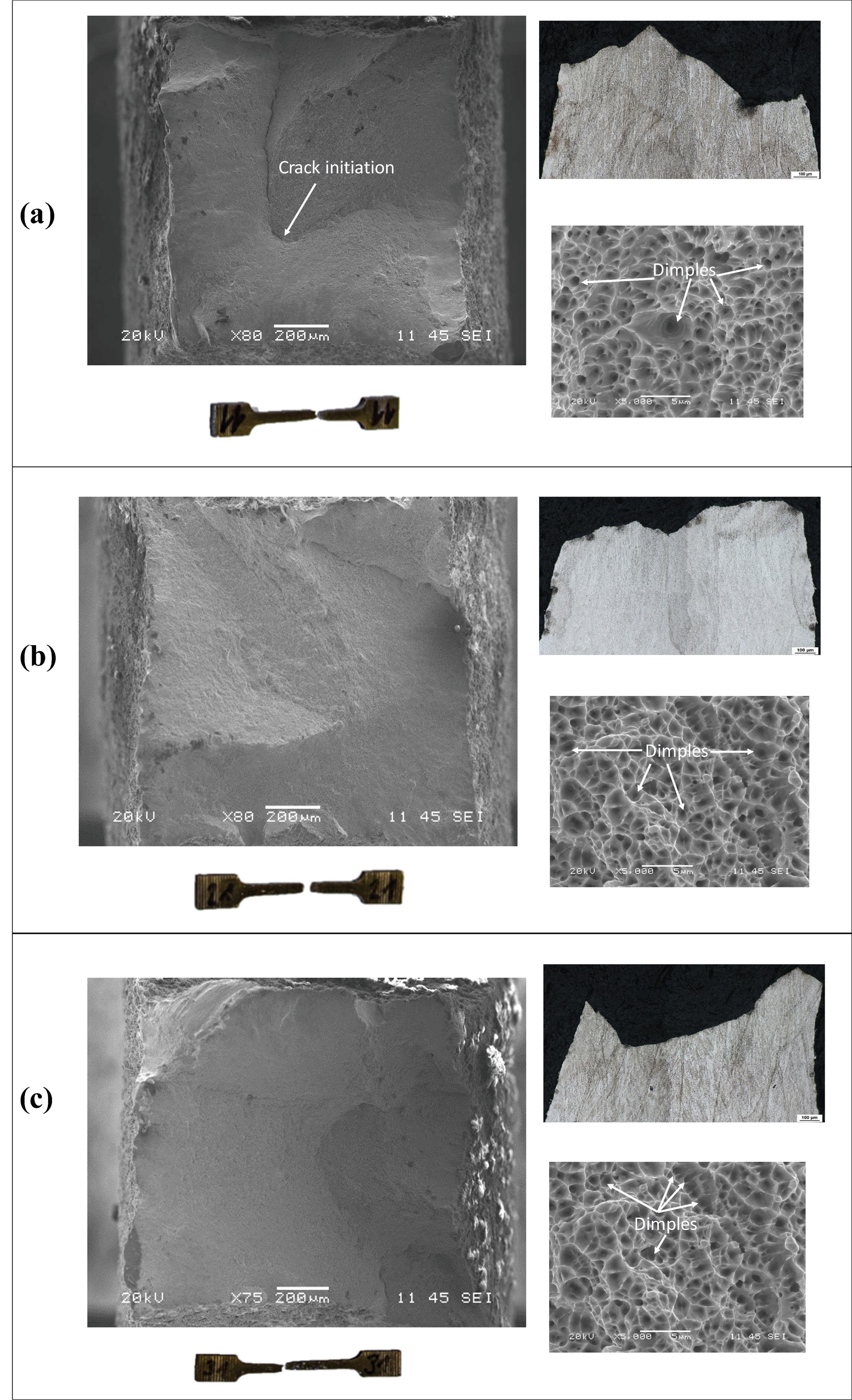
Figure 11 Fracture surface and morphology of deformed specimens (a) T11, (b) T21 and (c) T31.
2.3 Fracture Morphology
The fracture surface and morphology of the tensile samples that were machined closer to surface of the cube are shown in Figure 11, where it is visible, in the microstructure SEM images, the crack initiation spots and the dimple population. Microscopic images were captured, stitched and analyzed using a NIKON ECLIPSE MA200 in SW NIS-elements AR. It is clear that the additive manufactured stainless steels at both building directions show combinations of transcrystalline ductile fracture in all samples.
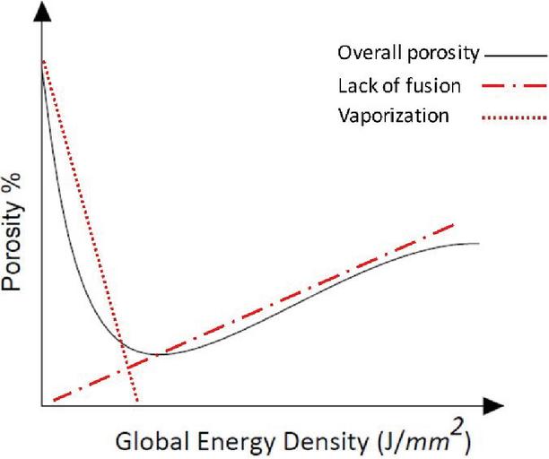
Figure 12 Relation between porosity and global energy density in DED process.
2.4 Porosity Evaluation
Micro-void defects or porosities have been found rather important in additive manufacturing processes, which could adversely affect the mechanical properties of AM-fabricated components. Spherical porosities (interlayer porosities) may appear in the keyhole mode [30] due to high power density, which could leave voids in the form of entrapped vapor within the deposited layers. Moreover, gas pores could be left during powder atomization process or the entrapment of the shielding gas in the molten pool, resulting in microscopic spherical voids in the fabricated layers. Another known cause of porosities in additively manufactured components may be attributed to the lack of fusion due to insufficient power delivery in order to penetrate the molten pool to the previously-deposited layer [11, 31]. The global energy density (GED) is referred to as a useful measure that establishes a link between the interlayer and intralayer porosities in DED processes. This parameter is quantified through a combination of several process parameters. Figure 12 schematically represents the link between the GED and porosity in DED manufacturing processes [32].
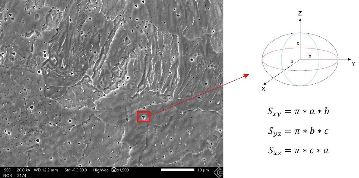
Figure 13 Microstructure of the fabricated component containing porosities; approximated ellipsoid pore shape with projected area and dimensions and Numerical framework.
Regarding the micromechanical observations, the test specimens were hot mounted in resin under heat and high pressure and polished for microscopic porosity analysis. Microscopic images were captured, stitched, and analyzed using a NIKON ECLIPSE MA200 in SW NIS-elements AR. Using this method, the microstructural porosity content is illustrated in Figure 13, where an approximated ellipsoid-shaped pores with dimensions and are assumed for utilization in the numerical procedure hereafter.
3 Numerical Analysis
3.1 Defect Analysis Using Generalized Mixture Rule (GMR) Approach
To establish relationships between porosity and resulting mechanical behavior in each tensile specimen, a generalized mixture rule (GMR) analysis was used. This utilization of this methodology was stressed out in [12, 33] served to provide a unified and rigorous mathematical framework that can describe physical properties of composites and multiphase materials such as void volume fraction and microstructural characteristics. Taking the porous media as a special case of two-phase composite structure, where null property pores are scattered within the solid component, the GMR is given by:
| (1) |
where is a specific mechanical property of the composite, and are respectively the volume fraction and mechanical property of the th material phase, where the composite consists of phases and , and is a fractal parameter that could represent geometrical features, distribution and orientation of pores [12]. The relation between mechanical properties of non-porous material and porous material is written as:
| (2) |
where is the porosity volume fraction and and are the strengths of the nonporous and porous materials, respectively. Equation (2) can be rewritten as:
| (3) |
in which the density of the composite phase and is the density of the solid bulk phase. In DED processes, the amount of the porosity is less than 10% and hence, using the Taylor expansion, according to [10]. Equation (3) can be simplified as:
| (4) |
The shape of the melt pool is illustrated in Figure 14, where is the laser diameter and is the overlap track. The size of the melt pool in the three directions can be calculated based on the following equations [12]:
| (5) | ||
| (6) | ||
| (7) |
where , and are the mass powder flow, the density of the powder and the deposition layer thickness, respectively.
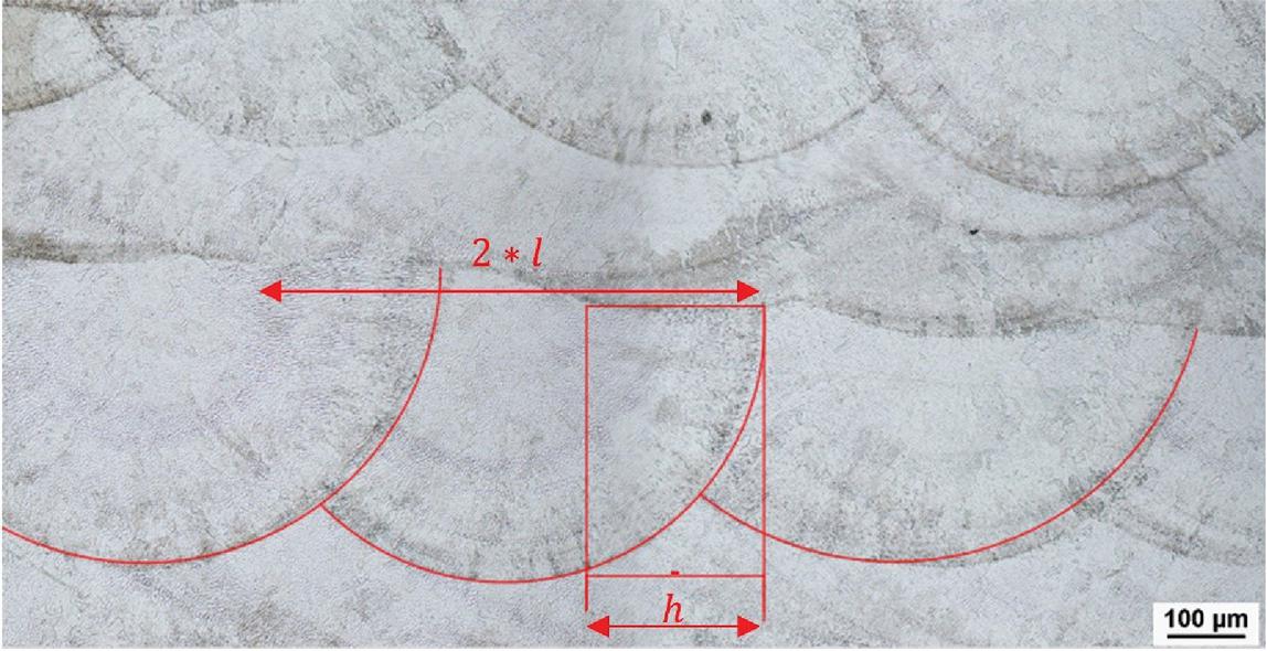
Figure 14 Melt pool dimensions schematic.
3.2 Calculation of Thermal Strains
To consider the process parameters, the thermal distortions which cause the lack of fusion and porosity is observed in this study. The Buckingham theorem is applied to AM process to make a relation between parameters as in Equations (8)–(10) [34, 35]. The thermal strains derived from different thermal gradients in every direction, , are calculated based on the following set of equations:
| (8) | ||
| (9) | ||
| (10) |
where is volumetric thermal expansion coefficient, is temperature gradient, is the volume of the molten pool and , and are thermal conductivity, specific heat and, density of the powder. The coefficients of , and represent the absorption value, laser power (W) and speed of the laser beam (mm/s). In the thermal strain equation expressed in Equation (8), the second moment of inertia of the pores, , with , and as the principal axes, as follows [12]:
| (11) |
where and represent the number the pores along , and axes, where is the width of the cubic component divided by the overlap tracking distance in the direction. The mathematical relation between thermal strains in Equation (8) and the size of pores in each direction that was visualized in Figure 16 can be given by curve fitting in the following expression [12]:
| (12) |
To determine the bulk porosity value of volume fraction in Equation (4), one can write [12]:
| (13) |
The -factor parameter in each direction can be associated with via the following relation [12]:
| (14) |
Where in the scope of the present research found to be the sum of in Equation (12).
3.3 Image Analysis
The ImageJ open source software [25, 36] is used as an additional tool for 2D image processing of the porosity in the components. As depicted in Figure 15, the porosity area (in percentage) in the components are quantified in the software by applying a threshold into greyscale micrographs covering an area of 41548 m to produce a binary image. Using this approach, the pores are distinguished from the bulk material with the sum of pore areas presented as a percentage of the total examined area. The image analysis evaluation reports an average of 0.67% porosity content for the samples [37, 38].
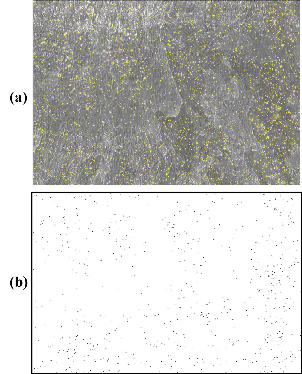
Figure 15 Representation of porosity content using ImageJ software.
3.4 Ductile Fracture Analysis
The sequence of ductile material degradation is characterized by nucleation, growth and coalescence of the micro-voids and micro-cavities. In the scope of present DED manufactured steel products, the pressure-dependent plasticity, thermodynamically-consistent ductile damage framework based on the Rousselier criterion is utilized [28, 29]. The flow potential associated with this model takes into account the effect of hydrostatic stress while the accumulation of damage is modelled through a single scalar field, namely the void volume fraction, which physically signifies the evolution of the porosities in the material bulk.
The Rousselier material model is established based on the decomposition of the free Helmholtz potential into the elastic , plastic and damage components as follows:
| (15) |
Where is the elastic strain and and are the internal variables, respectively describing the hardening variable and the void volume fraction. The Rousselier damage criterion uses the following flow potential based on the isotropic hardening and isotropy of damage:
| (16) |
where is the material hardening function, is the equivalent stress based on deviatory stress component , is the mean stress and and are the Rousselier model parameters affecting the material softening. The nucleation of the voids in this context is considered by employing an initial value of void volume fraction, , appears in the relative density, , indicative of the density of the damaged material to its reference state (intact material). The use of the relative density in the present ductile fracture framework is necessary as the hypothesis of incompressibility is no longer holds. Thus, the initial porosity value plays an important role in the construction of the present model while representing the nucleating voids, in which no damage will be generated if this parameter set to zero.
In light with the recent methodology proposed by the present authors in [27], the above ductile damage model is implemented within the finite element framework using ABAQUS software and by user coding in UMAT interface, while solely the local damage model is employed by neglecting the phase field crack coupling presented therein.
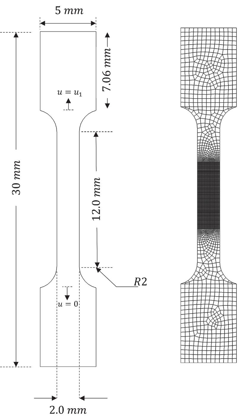
Figure 16 Geometry and mesh discretization of the tensile test samples.
Table 4 Material data used in the numerical simulation of tensile test samples
| Parameter | Symbol | Value | Unit | |
| Young’s modulus | 192.0 | GPa | ||
| Poisson’s ratio | 0.33 | |||
| Initial yield | MPa | |||
| Strength coefficient | 1078 | MPa | ||
| Hardening exponent | 0.81 | |||
| Model parameter | 302.2 | MPa | ||
| T11 | Model parameter | 2.0 | ||
| Initial porosity | 0.00025, 0.0005, 0.001 | |||
| Initial yield | MPa | |||
| Strength coefficient | 1036 | MPa | ||
| Hardening exponent | 0.76 | |||
| T31 | Model parameter | 309.5 | MPa | |
| Model parameter | 2.0 | |||
| Initial porosity | 0.00025, 0.0005, 0.0009 |
4 Results and Discussions
Based on the numerical framework presented in Section 3, the value of initial porosity is firstly identified by inverse finite element using the ductile fracture model that was described in Section 3.3. Furthermore, in a novel effort, a correlation between the presented GMR approach, ductile damage concept and image analysis is established: the calculated values from the GMR approach are validated via relevant comparisons with the obtained values of initial void volume fraction from ImageJ software and the calibrated ones using the FE framework, which in turn identified using the experimental data.
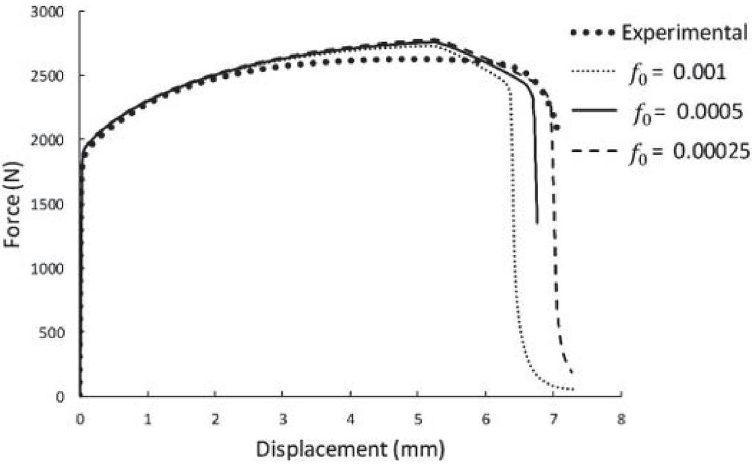
Figure 17 Variation of the global force-displacement graphs with the initial porosity for T11.
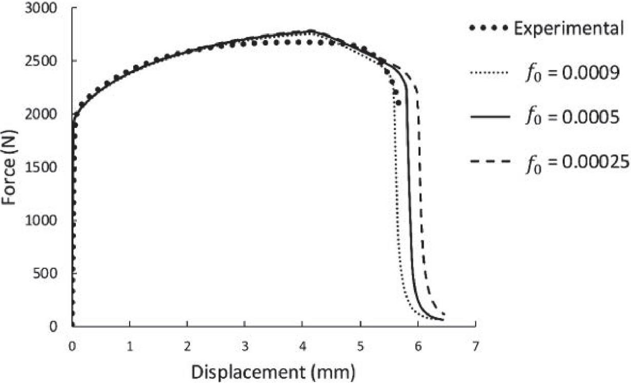
Figure 18 Variation of the global force-displacement graphs with the initial porosity for T31.
The sample geometry, boundary conditions and finite element mesh discretization are shown in Figure 16. The quadrilateral four-node, plane stress elements formulated with reduced integration method is used throughout the simulations. The set of material data utilized for the numerical simulation of samples T11 and T31 based on the Rousselier damage criterion are given in Table 4. As for the plastic hardening, Ludwik’s law is considered. By assuming the gauge length of 11 mm for the samples, the variation of the force-displacement is compared with the experimental data for T11 and T31 samples in Figures 17 and 18, respectively. Clearly, a faster growth rate of the voids can be observed by setting the initial void volume fraction to a higher value, which is also addressed in [39], whereby lowest displacement at fracture is obtained for . Following these results, the values of and are in the closest agreement with the experimental test data for T11 and T31 specimens, respectively.
These values are compared with the values obtained from the GMR approach in Table 5, in which a very good correlation can be found. Furthermore, the values determined using ImageJ analysis reveals a close agreement compared to the calculations based on the GMR approach. The above results confirm the validity of the employed GMR approach, as a rather phenomenological and purely mathematical tool, using finite element framework in the scope of the micromechanical damage model, which in turn was calibrated against the experimental measurements.
Table 5 Initial porosity values obtained from FEM and image J software compared with GMR approach
| Bulk Porosity Volume | |||
| Samples | Rousselier Model | Porosity Calculation | Fraction by ImageJ |
| T11 | 0.00025 | 0.0002676 | 0.00268 |
| T31 | 0.0009 | 0.0009027 | 0.0097 |
5 Conclusion
This study aims to primarily reveal the effect of the different deposition orientations on the mechanical properties and microstructural features in a DED-fabricated 316L component. By conducting numerical and experimental analyses, the remarkable conclusions in the paper include:
1. Stress-strain curves show obvious dependence of the material properties on the orientation of printing, as well as the distance of the coupons from the component cube surface.
2. The T11-T15 that were built normal to the loading direction were found to possess weaker metallurgical bonding between layers accounted for the relatively lower limits in yielding and ultimate tensile strength.
3. The presence of delta ferrite may cause increased hardness in comparison with the single-phase austenitic stainless steels, due to the solid solution hardening of Ni and Mo of the ferrite phase, and the internal strain hardening that occurs between the austenite and ferrite, caused by the different coefficients of thermal expansion.
4. Morphology studies show that when loading direction is parallel to the dendritic grains, for the building direction of T11-T15, could increase the fracture elongation since the ductility of the dendrites along the growth orientation was higher.
5. The porosity analyses conducted using image analysis making use of ImageJ software and FE framework in the scope of Rousselier pressure-dependent plasticity model, whereby the initial porosity values identified by comparing against the experimental data.
6. As an alternative approach and assuming the fabricated component as a special case of multiphase composites, the GMR framework was utilized to calculate the initial void volume fraction values from T11 and T31 samples and in a novel effort, a correlation between this approach and micromechanical damage theory was established through definition of initial porosity. Interestingly, these values were found to be in a close agreement with the identified values from image analysis and FE framework, which approves the soundness of the employed numerical frameworks.
7. In future studies, the further use of the GMR approach may be investigated to characterize the geometrical features and distribution of the pores in the manufactured components.
Acknowledgement
Authors gratefully acknowledge the funding of Projects ADDing (POCI-01-0145-FEDER-030490), co-financed by Fundo Europeu de Desenvolvimento Regional (FEDER) through Programa Operacional Competitividade e Internacionalização (COMPETE 2020) and national funds through Fundação para a Ciência e a Tecnologia (FCT), Portugal, and of Project Pre-Application Research of Functionally Graduated Materials by Additive Technologies No.: EF17_048/0007350, funded by the MEYSCzech Republic.
References
[1] Bandyopadhyay A, Bose S, Das S. 3D printing of biomaterials. MRS Bulletin 2015;40:108–14. https://doi.org/10.1557/mrs.2015.3.
[2] Tofail SAM, Koumoulos EP, Bandyopadhyay A, Bose S, O’Donoghue L, Charitidis C. Additive manufacturing: scientific and technological challenges, market uptake and opportunities. Materials Today 2018;21:22–37. https://doi.org/10.1016/j.mattod.2017.07.001.
[3] DebRoy T, Wei HL, Zuback JS, Mukherjee T, Elmer JW, Milewski JO, et al. Additive manufacturing of metallic components – Process, structure and properties. Progress in Materials Science 2018;92:112–224. https://doi.org/10.1016/j.pmatsci.2017.10.001.
[4] Mirkoohi E, Seivers DE, Garmestani H, Liang SY. Heat source modeling in selective laser melting. Materials 2019;12:1–18. https://doi.org/10.3390/ma12132052.
[5] ASTM International. ASTM International Technical Committee F42 on Additive Manufacturing Technologies 2013:19428.
[6] Mazumder J, Schifferer A, Choi J. Direct materials deposition: designed macro and microstructure. Materials Research Society Symposium – Proceedings 1999;542:51–63. https://doi.org/10.1557/proc-542-51.
[7] Hofmeister W, Griffith M, Ensz M, Smugeresky J. Solidification in direct metal deposition by LENS processing. Jom 2001;53:30–4. https://doi.org/10.1007/s11837-001-0066-z.
[8] Gasser A, Backes G, Kelbassa I, Weisheit A, Wissenbach K. Laser Additive Manufacturing: Laser Metal Deposition (LMD) and Selective Laser Melting (SLM) in Turbo-Engine Applications. Laser Technik Journal 2010;7:58–63. https://doi.org/10.1002/latj.201090029.
[9] Liu R, Wang Z, Sparks T, Liou F, Newkirk J. Aerospace applications of laser additive manufacturing. Elsevier Ltd; 2017. https://doi.org/10.1016/B978-0-08-100433-3.00013-0.
[10] Rashid A. Additive Manufacturing Technologies. CIRP Encyclopedia of Production Engineering 2019:39–46. https://doi.org/10.1007/978-3-662-53120-4\_16866.
[11] Sames WJ, List FA, Pannala S, Dehoff RR, Babu SS. The metallurgy and processing science of metal additive manufacturing. International Materials Reviews 2016;61:315–60. https://doi.org/10.1080/09506608.2015.1116649.
[12] Wolff S, Lee T, Faierson E, Ehmann K, Cao J. Anisotropic properties of directed energy deposition (DED)-processed Ti–6Al–4V. Journal of Manufacturing Processes 2016;24:397–405. https://doi.org/10.1016/j.jmapro.2016.06.020.
[13] Muller P, Mognol P, Hascoet JY. Modeling and control of a direct laser powder deposition process for Functionally Graded Materials (FGM) parts manufacturing. Journal of Materials Processing Technology 2013;213:685–92. https://doi.org/10.1016/j.jmatprotec.2012.11.020.
[14] Antony K, Arivazhagan N, Senthilkumaran K. Numerical and experimental investigations on laser melting of stainless steel 316L metal powders. Journal of Manufacturing Processes 2014;16:345–55. https://doi.org/10.1016/j.jmapro.2014.04.001.
[15] Zhang K, Wang S, Liu W, Shang X. Characterization of stainless steel parts by Laser Metal Deposition Shaping. Materials and Design 2014;55:104–19. https://doi.org/10.1016/j.matdes.2013.09.006.
[16] Li J, Deng D, Hou X, Wang X, Ma G, Wu D, et al. Microstructure and performance optimisation of stainless steel formed by laser additive manufacturing. Materials Science and Technology (United Kingdom) 2016;32:1223–30. https://doi.org/10.1080/02670836.2015.1114774.
[17] Kobryn PA, Semiatin SL. Mechanical Properties of Laser-Deposited Ti-6Al-4V P.A. Kobryn and S.L. Semiatin Air Force Research Laboratory, AFRL/MLLMP, Wright-Patterson Air Force Base, OH 45433-7817 2013:179–86.
[18] Ahmadi A, Mirzaeifar R, Moghaddam NS, Turabi AS, Karaca HE, Elahinia M. Effect of manufacturing parameters on mechanical properties of 316L stainless steel parts fabricated by selective laser melting: A computational framework. Materials and Design 2016;112:328–38. https://doi.org/10.1016/j.matdes.2016.09.043.
[19] Guo P, Zou B, Huang C, Gao H. Study on microstructure, mechanical properties and machinability of efficiently additive manufactured AISI 316L stainless steel by high-power direct laser deposition. Journal of Materials Processing Technology 2017;240:12–22. https://doi.org/10.1016/j.jmatprotec.2016.09.005.
[20] Suryawanshi J, Prashanth KG, Ramamurty U. Mechanical behavior of selective laser melted 316L stainless steel. Materials Science and Engineering A 2017;696:113–21. https://doi.org/https://doi.org/10.1016/j.msea.2017.04.058.
[21] N. Iqbal, E. Jimenez-Melero, U. Ankalkhope and JL. Microstructure and Mechanical Properties of 316L Stainless Steel Fabricated Using Selective Laser Melting. MRS Advances 2019;4:2431–9. https://doi.org/https://doi.org/10.1557/adv.2019.251.
[22] Saboori A, Aversa A, Bosio F, Bassini E, Librera E, De Chirico M, et al. An investigation on the effect of powder recycling on the microstructure and mechanical properties of AISI 316L produced by Directed Energy Deposition. Materials Science and Engineering A 2019;766:138360. https://doi.org/10.1016/j.msea.2019.138360.
[23] Bosio F, Saboori A, Lacagnina A, Librera E, de Chirico M, Biamino S, et al. Directed energy deposition of 316L steel: Effect of type of powders and gas related parameters. Euro PM 2018 Congress and Exhibition 2020.
[24] Saboori A, Toushekhah M, Aversa A, Lai M, Lombardi M, Biamino S, et al. Critical Features in the Microstructural Analysis of AISI 316L Produced By Metal Additive Manufacturing. Metallography, Microstructure, and Analysis 2020;9:92–6. https://doi.org/10.1007/s13632-019-00604-6.
[25] Rueden CT, Schindelin J, Hiner MC, DeZonia BE, Walter AE, Arena ET, et al. ImageJ2: ImageJ for the next generation of scientific image data. BMC Bioinformatics 2017;18:1–26. https://doi.org/10.1186/s12859-017-1934-z.
[26] Tu H, Schmauder S, Li Y. 3D optical measurement and numerical simulation of the fracture behavior of Al6061 laser welded joints. Engineering Fracture Mechanics 2019;206:501–8. https://doi.org/10.1016/j.engfracmech.2018.12.005.
[27] Azinpour E, Darabi R, Cesar de Sa J, Santos A, Hodek J, Dzugan J. Fracture analysis in directed energy deposition (DED) manufactured 316L stainless steel using a phase-field approach. Finite Elements in Analysis and Design 2020;177:103417. https://doi.org/10.1016/j.finel.2020.103417.
[28] Rousselier G. Dissipation in porous metal plasticity and ductile fracture. Journal of the Mechanics and Physics of Solids 2001;49:1727–46. https://doi.org/10.1016/S0022-5096(01)00013-8.
[29] Rousselier G. Ductile fracture models and their potential in local approach of fracture. Nuclear Engineering and Design 1987;105:97–111. https://doi.org/10.1016/0029-5493(87)90234-2.
[30] King WE, Barth HD, Castillo VM, Gallegos GF, Gibbs JW, Hahn DE, et al. Observation of keyhole-mode laser melting in laser powder-bed fusion additive manufacturing. Journal of Materials Processing Technology 2014;214:2915–25. https://doi.org/10.1016/j.jmatprotec.2014.06.005.
[31] Darvish K, Chen ZW, Pasang T. Reducing lack of fusion during selective laser melting of CoCrMo alloy: Effect of laser power on geometrical features of tracks. Materials and Design 2016;112:357–66. https://doi.org/10.1016/j.matdes.2016.09.086.
[32] Wolff SJ, Lin S, Faierson EJ, Liu WK, Wagner GJ, Cao J. A framework to link localized cooling and properties of directed energy deposition (DED)-processed Ti-6Al-4V. Acta Materialia 2017;132:106–17. https://doi.org/10.1016/j.actamat.2017.04.027.
[33] Ji S, Gu Q, Xia B. Porosity dependence of mechanical properties of solid materials. Journal of Materials Science 2006;41:1757–68. https://doi.org/10.1007/s10853-006-2871-9.
[34] Mukherjee T, Zuback JS, De A, DebRoy T. Printability of alloys for additive manufacturing. Scientific Reports 2016;6:1–8. https://doi.org/10.1038/srep19717.
[35] R. Byron Bird Warren E. Stewart Edwin N. Lightfoo, Bird RB, Stewart WE, Lightfoot EN. Transport Phenomena, Revised 2nd Edition. John Wiley & Sons, Inc 2006:780. https://doi.org/10.1002/aic.690070245.
[36] Abr moff MD, Magalh es PJ, Ram SJ. Image processing with imageJ. Biophotonics International 2004;11:36–41. https://doi.org/10.1201/9781420005615.ax4.
[37] Del Guercio G, Galati M, Saboori A, Fino P, Iuliano L. Microstructure and Mechanical Performance of Ti–6Al–4V Lattice Structures Manufactured via Electron Beam Melting (EBM): A Review. Acta Metallurgica Sinica (English Letters) 2020;33:183–203. https://doi.org/10.1007/s40195-020-00998-1.
[38] Izadi M, Farzaneh A, Gibson I, Rolfe B. The Effect of Process Parameters and Mechanical Properties of Direct Energy Deposited Stainless Steel 316. Solid Freeform Fabrication 2017: Proceedings of the 28th Annual International Solid Freeform Fabrication Symposium – An Additive Manufacturing Conference 2017:1058–67.
[39] Gao X, Wang T, Kim J. On ductile fracture initiation toughness: Effects of void volume fraction, void shape and void distribution. International Journal of Solids and Structures 2005;42:5097–117. https://doi.org/10.1016/j.ijsolstr.2005.02.028.
Biographies
Roya Darabi is a Ph.D. student at the faculty of mechanical engineering of University of Porto since September 2019. She received her master degree in manufacturing engineering from Arak University of technology in 2015 and her bachelor degree in mechanical engineering from Iran University of science and technology (IUST), Tehran, in 2012. After achieving her master degree, she has been member of the Iran’s National Elites Foundation since 2016. She attended Machine Sazi Arak (M.S.A), the Middle East leading oilfield services provider and affiliated by IDRO Iran, as high-pressure oil and gas equipment and refinery industries designer between 2012 and 2018. Then she joined the advanced manufacturing technology group (UTAF) at INEGI in September 2018.
Erfan Azinpour is a post graduate researcher at the Faculty of Engineering of University of Porto. After his Ph.D. graduation in March of 2020 which was partly conducted under the fellowship position at Institute of Science and Innovation in Mechanical and Industrial Engineering (INEGI) since July 2016, he continued his research at the faculty in the field of mechanical engineering to this date. The research areas are revolved around the development of numerical methods and strategies in fracture and damage mechanics, primarily in brittle and ductile material context, and assessment of reliability and performance of such methods in reproducing the structural failures in real life events and in the scale of industrial applications.
Jose Cesar de Sa, is a Full Professor at the Faculty of Engineering, University of Porto (FEUP) Portugal. He graduated in Civil Engineering at FEUP in 1976 and has a Ph.D. in Civil Engineering at the University of Swansea, U.K., in 1986. He is currently the President of APMTAC, the Portuguese Association of Theoretical, Applied and Computational Mechanics and Member of the Managing Board of ECCOMAS-European Community on Computational Methods in Applied Sciences.
Margarida Machado hold a MSc and PhD degree in Biomedical Engineering from University of Minho (Guimarães, Portugal). During her doctoral studies, Margarida was a visiting scholar of Technical University of Lisbon (Portugal) and University of Florida (Gainesville, USA). Her PhD work in the scope of Computational Biomechanics had been distinguished internationally twice, firstly by EUROMECH (2009) and later by ASME (2011). Since 2013, Margarida Machado is working at INEGI (Institute of Mechanical Engineering and Industrial Management) in Porto (Portugal) as a senior research, where she starts developing a career in research management. From 2016 and 2020, she devoted some work in the field of Additive Manufacturing by means of the co-supervision of a PhD Thesis, the participation in some related scientific projects and the coordination/management of several innovation projects and/or technological platforms/networks (such as Vanguard). She is now representing INEGI in two Knowledge Innovation Communities (KICs) of European Institute of Technology (EIT), namely EIT-Manufacturing and EIT-Raw Materials, and coordinating/supporting the development and fundraising of strategic integrated projects/proposals, covering the four main knowledge vectors of INEGI: (1) Advanced Manufacturing Technologies and Processes; (2) Smart Materials and Structural Solutions; (3) Product and System Development; (4) Energy and Environment.
Ana Rosanete Reis is assistant Professor at the Faculty of Engineering of the University of Porto, and author and co-author of several articles presented at international congresses and scientific journals. PhD in Materials Engineering from the University of Ghent (Belgium). Director of INEGI’s Advanced Manufacturing Technologies since 2008, specializes in manufacturing process namely Sheet metal Forming and casting. Is responsible for several research projects in monitoring and control of advanced manufacturing processes. Has collaborated in numerous projects with the industry, namely in the field of metalworking and industrial equipment.
Josef Hodek graduated from West Bohemian University in Pilsen, Czech Republic; Ph.D. degree in Electrical engineering in 2001. Josef worked as an R&D engineer for Haimer GmbH, Germany, and as an induction heating consultant. Josef joined COMTES FHT in 2010 as a FEM researcher. His main interests are FEM models of the metalworking processes as additive manufacturing process and induction heating.
Jan Dzugan graduated from West Bohemian University in Pilsen, Czech Republic in 1995 where he also did his Ph.D in the field of Materials science in 1999. Already during his Ph.D studies he was employed at SKODA Research institute in Pilsen where he was dealing with mechanical testing. He worked 4 years at nuclear research institute Helmholtz Dresden-Rossendorf, Germany, where he was dealing with facture mechanics based service life assessment of nuclear power plants. Subsequently, he was working in the field of residual service life prolongation of Shinkansen wheel sets at Fracture Research Institute of Tohoku University in Japan. From 2006 he joined COMTES FHT in Pilsen, Czech Republic, where he established mechanical testing laboratory and later become R&D Director. Prof. Dzugan is author or co-author of over 200 scientific papers. He has been involved in over 30 publically funded projects. He is lecturing at West Bohemian University in Pilsen. He is supervisor or Bc., MSc. and Ph.D. students. His main scientific interest are: mechanical testing and additive manufacturing. He is member of many international technical organizations, e.g. ASTM, where he is leader of two groups dealing with miniature specimens standardization in general testing and for additive manufacturing processes.
European Journal of Computational Mechanics, Vol. 29_2-3, 223–254.
doi: 10.13052/ejcm2642-2085.29233
© 2021 River Publishers