Study of Fingering Dynamics of Two Immiscible Fluids in a Homogeneous Porous Medium with Considering Wettability Effects Using a Pore-Scale Multicomponent Lattice Boltzmann Model
Eslam Ezzatneshan* and Reza Goharimehr
Faculty of New Technologies and Aerospace Engineering, Shahid Beheshti University, Tehran, Iran
E-mail: e_ezzatneshan@sbu.ac.ir
Corresponding Author
Received 18 April 2021; Accepted 23 September 2021; Publication 26 October 2021
Abstract
In the present study, a pore-scale multicomponent lattice Boltzmann method (LBM) is employed for the investigation of the immiscible-phase fluid displacement in a homogeneous porous medium. The viscous fingering and the stable displacement regimes of the invading fluid in the medium are quantified which is beneficial for predicting flow patterns in pore-scale structures, where an experimental study is extremely difficult. Herein, the Shan-Chen (S-C) model is incorporated with an appropriate collision model for computing the interparticle interaction between the immiscible fluids and the interfacial dynamics. Firstly, the computational technique is validated by a comparison of the present results obtained for different benchmark flow problems with those reported in the literature. Then, the penetration of an invading fluid into the porous medium is studied at different flow conditions. The effect of the capillary number (), dynamic viscosity ratio (), and the surface wettability defined by the contact angle () are investigated on the flow regimes and characteristics. The obtained results show that for , the viscous fingering regime appears by driving the invading fluid through the pore structures due to the viscous force and capillary force. However, by increasing the dynamic viscosity ratio and the capillary number, the invading fluid penetrates even in smaller pores and the stable displacement regime occurs. By the increment of the capillary number, the pressure difference between the two sides of the porous medium increases, so that the pressure drop p along with the domain at is more than that of computed for . The present study shows that the value of wetting fluid saturation at is larger than its value computed with that is due to the more tendency of the hydrophilic medium to absorb the wetting fluid at . Also, it is found that the magnitude of computed for both the contact angles is decreased by the increment of the viscosity ratio from to . The present study demonstrates that the S-C LBM is an efficient and accurate computational method to quantitatively estimate the flow characteristics and interfacial dynamics through the porous medium.
Keywords: Porous media, immiscible fluids, fingering regimes, lattice Boltzmann method.
1 Introduction
Studying fluid transport through porous media is crucial for the determination of flow characteristics and patterns in many industrial applications, such as the core part of fuel cells, filters, microfluidics, and oil recovery from reservoirs. However, investigating the interfacial dynamics of multicomponent multiphase flows in complex pore-scale geometry is a most challenging problem [1]. The experimental setup for this type of fluid flows is expensive and time-consuming. Also, the traditional macroscopic computational methods based on the Navier-Stokes (N-S) equations need efficient meshing algorithms and massive computational resources for the simulation of multiphase flows in porous geometries [2]. Therefore, in recent decades, researchers have shown a great interest in mesoscopic techniques, such as the lattice Boltzmann method (LBM) [3, 4]. The remarkable versatility of LBM makes this method widely used for the simulation of fluid flows in applications involving interfacial dynamics in porous geometry. The kinetic nature of the LBM allows to model of the phase separation, interparticle interactions, and interfacial phenomena in multiphase flows [5–7]. Also, in contrast with the N-S based flow solvers, multiphase models based on the LBM do not need any additional algorithms for tracking or capturing the interfacial dynamics in pore-scale complex geometries that make them more efficient computational methods for multiphase flows.
Several models based on the LBM are employed for the simulation of multiphase flows [8–12]. Among these models, the pseudopotential Shan-Chen (S-C) model [9, 10] is most famous for modeling two immiscible fluids transport through a heterogeneous porous medium due to its capability for simulation of multicomponent multiphase flows and simplicity in implementation with appropriate accuracy and performance [13]. The S-C LBM, however, needs to employ a combination of an appropriate forcing scheme and a collision operator to accurately predict the flow properties in porous media and preserve the numerical stability in the interfacial region, particularly for two-phase flows at high-density ratios [14]. The multi-relaxation-time (MRT) collision operator [15, 16] is an efficient technique that can sophistically reduce numerical instabilities at the liquid-gas interface and allows the LBM to achieve high density and viscosity ratios. Kuzmin et al. [17] have investigated the advantages of dealing with the MRT collision operator in the study of capillary effects and the formation of the droplets. Yu and Fan [18] have shown that using the MRT-LBM leads to a considerable reduction in the spurious currents in the interfacial region of two-phase flows. Recently, the MRT S-C LBM is also implemented for studying various flow problems, e.g. the simulation of two-phase flow through porous media [19, 20]. The unphysical dependency of the magnitude of the density ratio to the value of the viscosity ratio is also a drawback of the S-C LBM that can be eliminated by incorporating an appropriate forcing scheme, such as the exact difference method (EDM) [21, 22].
By applying these improvements, the S-C LBM can be used for studying the fluid flow characteristics in porous geometries. Pan et al. [23] have shown that the unphysical dependency of the relative permeability of a porous medium on the viscosity of the fluid is significantly reduced by incorporating the MRT collision operator in the LBM-based simulations. Huang et al. [24] performed a numerical experiment by employing the color gradient model and the MRT collision operator to simulate immiscible binary fluids in a porous geometry. Their findings show that the MRT collision operator can dramatically increase the numerical stability of the model. Gao et al. [25] have also demonstrated the capability of the S-C LBM for predicting the two-component fluid dynamics in pore-scale geometry. Recently, Xu and Liu [26] have implemented a color-gradient MRT-LBM to study the fluid flow characteristics such as the relative permeability in realistic Berea sandstone. Ju et al. [27] also have employed a color-gradient MRT-LBM for studying the effect of different density ratios and porous structures on the fluid distribution characteristics in a two-dimensional domain.
In all the aforementioned works based on the S-C LBM, the dependency of the density and viscosity ratios is not eliminated in the simulation of multiphase flows through porous media. This unphysical dependency can seriously impact the accuracy of the numerical results, particularly for the two-phase flow simulations at high-density ratios [28]. In the present paper, the implementation of a two-component S-C LBM by using the MRT collision operator is considered to ensure the stability of the numerical solutions presented. Also, the EDM forcing scheme is employed to eliminate the dependency between the density and viscosity ratios that brings the accuracy of the numerical results closer to the physical flow structures expected. The capability and performance of the present computational technique based on the multicomponent LBM are examined by validation of different multicomponent fluid flow problems with considering the wettability effects. Then, the characteristics and structure of multicomponent fluid flow through a porous medium are studied at different flow conditions and the obtained results are discussed from the physical point of view.
The rest of the paper is organized as follows: A brief overview of the numerical scheme applied based on the S-C LBM is presented in Section 2. Section 3 deals with the results obtained based on the present study. The validation of the computational technique and the discussions made based on the resolved flow patterns are provided in Section 3. Finally, some conclusions are summarized in Section 4.
2 Numerical Method
The governing equations of the S-C LBM [9, 10] implemented for the simulation of binary fluids dynamics in a two-dimensional (2D) computational domain are presented in this section. Herein, the MRT collision operator and EDM forcing scheme are used to improve the stability and accuracy of the numerical method employed. The governing equation of the standard single relaxation time (SRT) LBM with EDM forcing scheme is given as [28]:
| (1) |
where is the particle distribution function which demonstrates the distribution of particles with the velocity in position x at time . The lattice speed is the ratio of the lattice space to the time step and is the relaxation time for each component that is related to the kinematic viscosity. The superscript defines each component and the subscript indicates the discrete velocity directions. According to the 2D lattice structure D2Q9 employed in the present work, the set of discrete velocities is defined as:
| (2) |
The right-hand side of Equation (1) represents the SRT collision operator which leads the system to the local Maxwellian equilibrium on the time scale . The is equilibrium particle distribution function for component , which is defined as:
| (3) |
The speed of sound for the LBM in D2Q9 framework is equal to [29], and is the weighting coefficient, where , and . The macroscopic flow properties, including the density and velocity of the component -th, can be obtained using and , respectively. The equilibrium local velocity in Equation (3) is defined as:
| (4) |
The term in the EDM forcing scheme is also used to impose the interaction force between the components in the numerical solution by
| (5) |
where the total interaction force is a combination of the fluid-fluid cohesion force , the fluid-solid adhesion force , and the external body force [30]:
| (6) |
The is given as [31]:
| (7) |
where is the cohesive force coefficient which indicates the attractiveness (repulsiveness) of the interaction force between particles of component and . It should be noted that by adjusting the , various surface tension between the components can be achieved [30, 31]. Similarly, the adhesive force between particles of each component and the solid surface is defined as [31]:
| (8) |
The indicator is used to turn the adhesion force on for the solid nodes by , and turn it off on the fluid nodes by in the numerical solutions performed. The mean-field potential function defines the relevance between the interaction strength and the mass of the particles. In the S-C model, depends on the local density as [10]:
| (9) |
In the represented formulation, the is also calculated by Equation (9), where instead of solid wall density, the adhesion parameter determines the wettability of the surface. It is shown that the adhesion parameter for the wetting component should be negative but having the same absolute value for the non-wetting component [30–33].
For the incorporation of the MRT collision operator in the LBM presented in Equation (1), the right-hand side of the equation is rewritten as:
| (10) |
Herein, and are the distribution function and the equilibrium distribution function in moment space, respectively. The transformation matrix and the relaxation matrix can be defined as follows [40]:
| (11) | ||
| (12) |
where the values of , and should be nonzero in order to maintain the influence of the trapezoidal integration in Equation (10) [15]. In the present work, these parameters are set to be , , and .
3 Results and Discussions
In this section, the results obtained based on the present numerical algorithm are presented for the simulation of the two immiscible fluids dynamics through a porous medium with various wetting conditions. At first, a validation study is performed to demonstrate the accuracy and performance of the computational model implemented based on the S-C LBM. Herein, three well-known benchmark multicomponent fluid flow systems are considered; (I) the phase separation phenomenon is studied to demonstrate the stability and robustness of the present solution methodology for the simulation of such a complex flow problem, (II) the equilibrium state of a droplet placed on a flat surface is modeled to validate the intrinsic contact angle computed based on the S-C LBM by considering different wetting conditions, and (III) the capillary intrusion of a liquid into a pore channel is investigated to verify the Washburn’s law. The latter test case is used to evaluate the capability of the numerical model for the prediction of interfacial dynamics in the penetration process of the liquid phase into pores of a medium. After ensuring the accuracy and efficiency of the present algorithm, it is employed to study the liquid mobility and imbibition into the porous medium by considering different wetting conditions, and the results obtained are discussed from the physical point of view. It should be noted that all flow parameters in the present study are in the lattice unit [34].
3.1 Model Validation
The phase separation phenomenon can be occurred in a multicomponent fluid flow system when the interparticle interaction force drives a fluid drops to coalescence and separate from another one. The parameter is responsible for controlling the interaction force between the components in the S-C LBM. By changing the magnitude of , the capability of the present numerical scheme based on the S-C LBM is demonstrated for simulation of the phase separation phenomenon in a 2D square domain with periodic boundaries. The flow-field is discretized with lattice nodes and the simulation is initialized by a random density distribution. Herein, two immiscible fluids are considered in the system, where and are the main and dissolved densities of fluid 1 and fluid 2 respectively. Accordingly, the initial density in the flowfield is computed by . The present simulation is performed for and the parameter can be varied from zero until , where the numerical instabilities occurred.
Figure 1 demonstrates the sequence of the phase separation presented by the density field for two dynamic viscosity ratios of , and at . With beginning the simulation, the coalescence phenomenon occurs and the two fluids start to separate in the form of small droplets and ligaments. The small droplets coalescence and form a larger region filled with each fluid as the time evolves. The results obtained by applying the S-C LBM show that the phase separation is slow for the system with the low viscosity ratio . As shown at the given time in Figure 1, the coalescence phenomenon has generated big slugs in the two-phase flowfield at the higher viscosity ratio and . However, at the same time for the mixture with , the small droplets are still adhering to each other and form ligaments. This flow treatment can be due to the smooth dynamics of the interfacial region of heavy drops through the lighter fluid when the viscosity ratio is high. In contrast, when two fluids have similar viscosity, the dynamics of the small droplets of one fluid suspended in another fluid are slow that postpones the coalescence process. It should be noted that the simulation of the multicomponent system at the very high dynamic viscosity ratio is presented to show that the S-C LBM method by employing the MRT collision operator is numerically stable for investigation of complex multicomponent fluid flows.
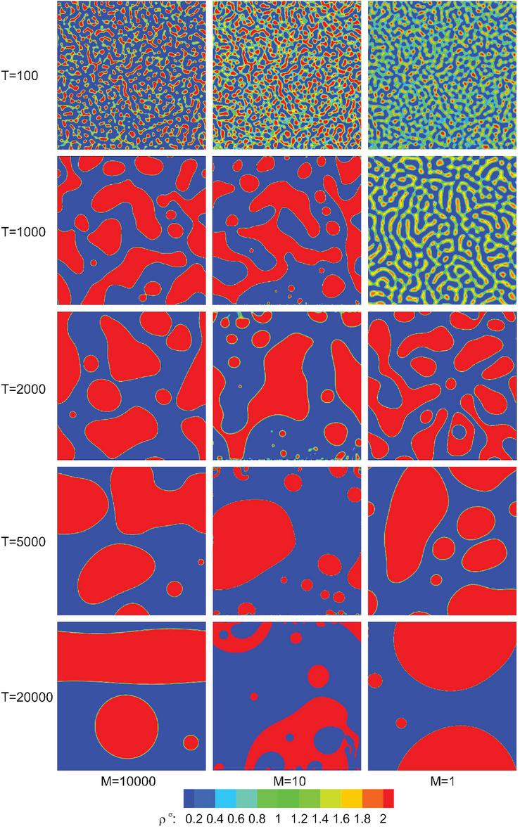
Figure 1 Computed density field of phase separation in a multicomponent system at different dynamic viscosity ratios. The coalescence process started quickly for higher viscosity ratios.
The occurrence of the phase separation phenomenon depends on the magnitude of [35]. Figure 2 illustrates the obtained results for the variation of the density of fluid 1 and the smaller dissolved density of fluid 2 by changing the magnitude of . The parameters presented in this figure are scaled according to the initial density . As can be seen in Figure 2, the scaled density value in the flow domain remains constant for that indicates the phase separation does not occur in this condition. Consequently, the surface tension computed based on the present simulation is zero due to the lack of the interfacial region in the flow domain. At , a weak interaction force appears between the components, so that it hardly preserves the shape of the initialized small droplets. By increasing of , the intense interaction force leads the small droplets to coalescence in the shape of ligaments and the phase separation occurs. By formation of an interface between two fluids, the value of surface tension increases that confirms the existence of a two-phase flow system. The present study shows that by increasing , the magnitude of the scaled density of the system reaches to the constant value of 1 that verifies the accuracy of the present method based on the findings in the literature [35, 36]. It should be noted that increment of the interaction force by increasing of causes the formation of droplets with higher surface tension and sharper interface which both of them impact the numerical stability of the solution.

Figure 2 The phase separation phenomenon occurs by increment of that controls interaction force between different components. With the appearance of interfacial region due to phase separation, surface tension also increases.
For a 2D fluid droplet suspended in another fluid, the surface tension causes a pressure difference between the outside and inside of the droplet. The Laplace law [37] defines a linear relationship between and for a certain droplet radius as:
| (13) |
For evaluation of the accuracy of the present model for predicting the flow characteristics of the phase separation phenomenon studied, the surface tension of the obtained results for the large droplets after coalescence is verified by the Laplace law. Figure 3 compares the computed values for versus by setting various . The linear relation between these two parameters in this figure shows that the present numerical results based on S-C LBM satisfy the Laplace law. The slope of the line represents the value of the surface tension of the multicomponent system studied which is obtained , and for , 4 and respectively.
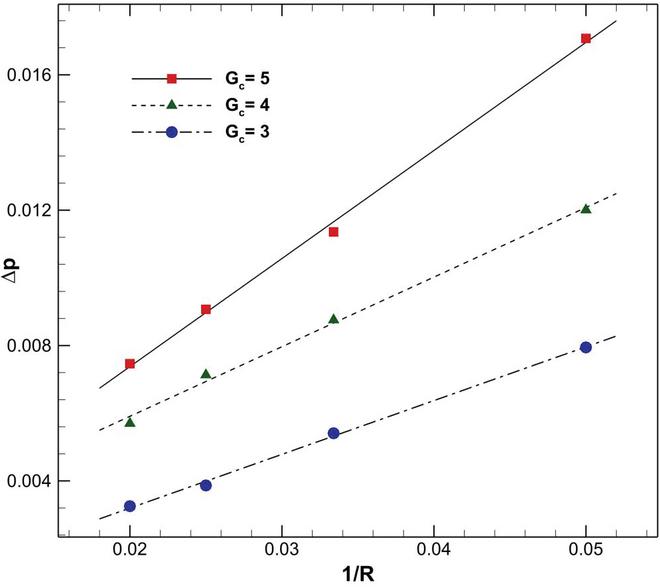
Figure 3 Satisfaction of Laplace law by present results obtained for phase separation phenomenon at different interaction forces imposed by .
The accuracy and capability of the present S-C LBM for imposing the wetting condition are investigated by the simulation of the equilibrium state of a droplet on a solid wall. Herein, a droplet with radius is initialized tangentially on the bottom wall of a rectangular computational domain with the grid size of . The density distribution is defined by a hyperbolic function to preserve the stability of the numerical solution at the beginning of iterations [13]. The adhesion parameter is incorporated to define the wettability of each component on the wall surface that is defined by the contact angle . For the wetting component, is set to be negative, but the same absolute magnitude should be set for the non-wetting component [33, 38, 39], . Figure 4 shows the equilibrium state of the droplet on the bottom wall at different wetting conditions. The spreading of the droplet on the surface by increasing the adhesion coefficient is obvious in this figure. The obtained results for the contact angle by using the present S-C LBM are also compared with those reported by Huang et al. [30] in Figure 4 which shows a good agreement.
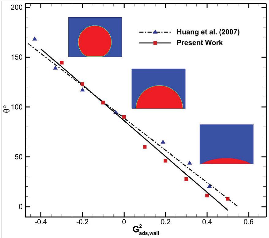
Figure 4 Comparison of contact angle obtained by present numerical method for equilibrium state of a droplet on a flat surface with that reported by Huang et al. [30] at different wetting conditions.
Washburn’s law [40] is also considered to validate the accuracy of the present numerical scheme for the predicting of the interface dynamics in the pore-scale due to the capillary effect. In this problem, the capillary intrusion of a fluid with surface tension into a single 2D channel with width and length is computed. The analytical solution of the 2D Washburn equation is defined as follows [41]:
| (14) |
where is the average transition time, is the initial position of the interface, and is the contact angle. Herein, a rectangular computational domain with the grid size of is provided for this problem with the periodic boundary condition in the -direction, and the wall boundary condition is imposed on the top and bottom sides. A channel with the length and width of and , respectively, are placed in the middle of the domain. Initially, the flowfield is filled with two immiscible fluids. The fluid with the dynamic viscosity of fills the left rectangular reservoir with the length of , and the fluid with the dynamic viscosity of fills the channel and space in the right end of the computational domain. In the present study, the dynamic viscosity ratio is set to be , the surface tension is , and the contact angle of the wetting fluid with the wall surface is . Figure 5(a) shows the computational domain after iterations, where the fluid with higher dynamic viscosity penetrates into the channel due to the capillary effect. Figure 5(b) demonstrates the comparison of the instantaneous interface position obtained based on the present numerical solution with that of the analytical solution obtained from Equation (14). The present results are in good agreement with the analytical solution that shows the capability and accuracy of the S-C LBM employed for the simulation of multicomponent fluid flow patterns and characteristics in pore-scale geometries.
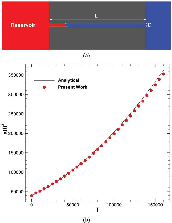
Figure 5 Results obtained based on present numerical scheme for Washburn’s problem at and . (a) Capillary intrusion of liquid phase into a pore channel at T 25000, and (b) instantaneous variation of interface position in comparison with the analytical solution.
3.2 Fingering Structure of Immiscible Fluids Flow Through Porous Media
The description of the immiscible displacement in a porous medium is provided in this section according to the simulation results obtained for fingering structures by the present S-C LBM. In addition to the dynamic viscosity ratio , the capillary number, , is the effective dimensionless number that is defined as [42]:
| (15) |
In this relation, and are the dynamic viscosity and velocity of the advancing non-wetting fluid, respectively, and is the fluid-fluid contact angle. For the investigation of two-component flow transport through a porous medium, a homogeneous porous geometry is generated by a distribution of randomly shaped obstacles in a domain with grid resolution. The geometry of the porous medium used in the present study and the boundary conditions of the flow domain is shown in Figure 6. The area of the obstacles is roughly equal to , the throat height is between and , and the pore space area will is about . The velocity inlet and pressure outlet boundary conditions are imposed in the left and right boundaries, respectively, and the top and bottom sides are considered periodic. The wetting fluid is defined by the higher density (red color) which invades the non-wetting fluid with lower density (blue color) in the flow domain. Such an invasion produces some fingering regimes (see a schematic view in Figure 7), that their origin can be the surface or geometrical characteristics of a porous medium in nature. Herein, the fingering regime occurs for the wetting fluid flow through the porous medium considered due to the random generation of the shape of obstacles and the wetting condition of the solid surfaces.
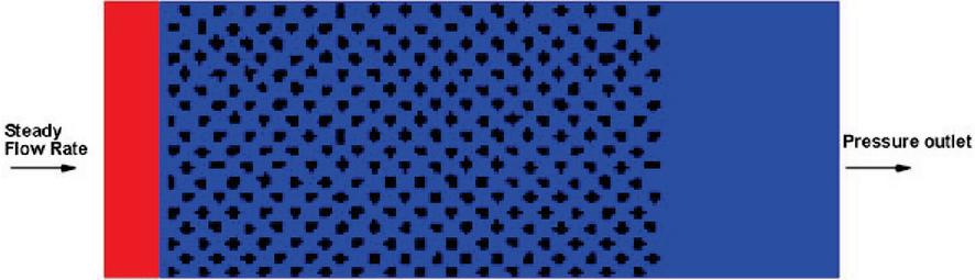
Figure 6 Geometry and boundary conditions of porous medium used in the present study.
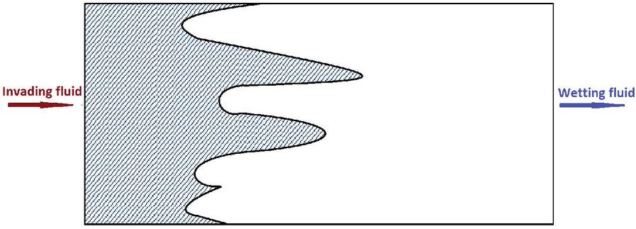
Figure 7 A schematic of fingering structures in a domain.
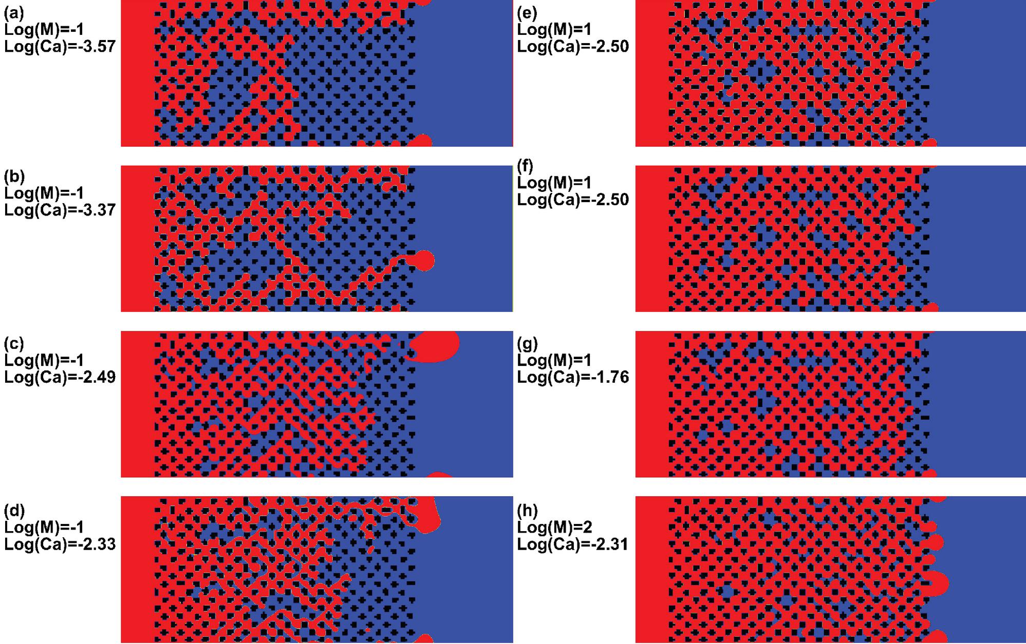
Figure 8 Two immiscible fluids flow patterns in the porous medium obtained by present simulations for different flow conditions with .
Figure 8 illustrates the two-component fluid flow patterns, simulated by the present numerical model at various viscosity ratios and capillary numbers, which are represented in a logarithmic scale at . All simulations are performed at , which leads to . As it can be seen for (), some fingers move toward the downstream of the domain by a driving force produced by the viscous force of the invading fluid and capillary forces. This regime is known as viscous fingering [42] which is distinguished by increasing the capillary number. When the effect of the capillary force becomes dominant, the invaded fluid (wetting fluid) can penetrate more pores, rather than moving to downstream and as a result, the saturation of the invading fluid decreases (Figure 8, (a)–(d)). By increasing the dynamic viscosity ratio, (), the present solution results in Figure 8, (e)–(g), show that the invading fluid occupies more pores in the media. For higher capillary numbers with , the fingers stretch all around the domain in any arbitrary directions and the invading fluid penetrates even in smaller pores. In this case, the moving interface of the invading fluid is flattened that is known as the stable displacement regime [42]. It should be noted that the detached drop of the invading fluid observed in Figure 8(c) can be explained by the fluid flow through the medium the non-wetting nature of the invading fluid. The present numerical solution demonstrates that the invading fluid tends to leak out of the porous medium after reaching the right side of the medium. The leaking red fluid then forms a cap in the leak site. At this point, the surface tension tends to reshape the grew cap into a circle, while the non-wetting nature of the invading fluid makes a large contact angle between the cap and the obstacle that enhances the reshaping process. Therefore, the formed cap tends to become a droplet, which the fluid flow through the medium separates it from the leak site and pushes it downstream.
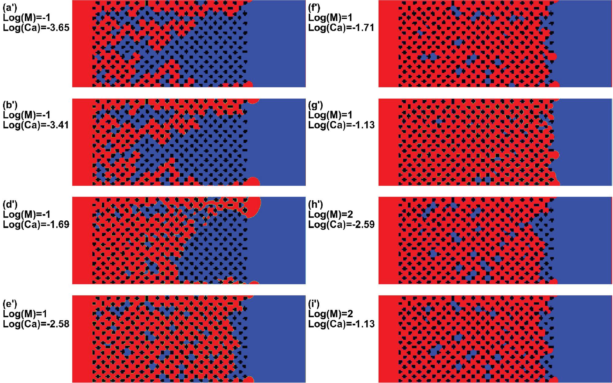
Figure 9 Two immiscible fluids flow patterns in the porous medium obtained by present simulations for different flow conditions with .
A similar study is carried out for the porous geometry when the contact angle of obstacles is set to be . For this case, the fingering patterns captured by employing the S-C LBM are presented in Figure 9. The comparison of fingering structures obtained with the hydrophilic wetting condition is considered for the solid surfaces at and shows homologous flow treatment through the porous medium. The fingering structure and the displacement pattern of the invading fluid obtained based on the present study in Figures 8 and 9 are categorized as the viscous fingering and stable displacement, depending on the capillary number and the viscosity ratio between two fluids. In Figure 10, the phase diagram is used to describe these flow structures by and in comparison with the schematics reported in the previous works [43, 44]. In this figure, the results obtained for and are presented by letters and , respectively, according to the labels of Figures 8 and 9. In the range of magnitudes set for and , the displacement patterns captured in the present study are compatible with those reported in the literature [43, 44] that shows the present numerical method is accurate enough for the simulation of immiscible flow structures through porous media.
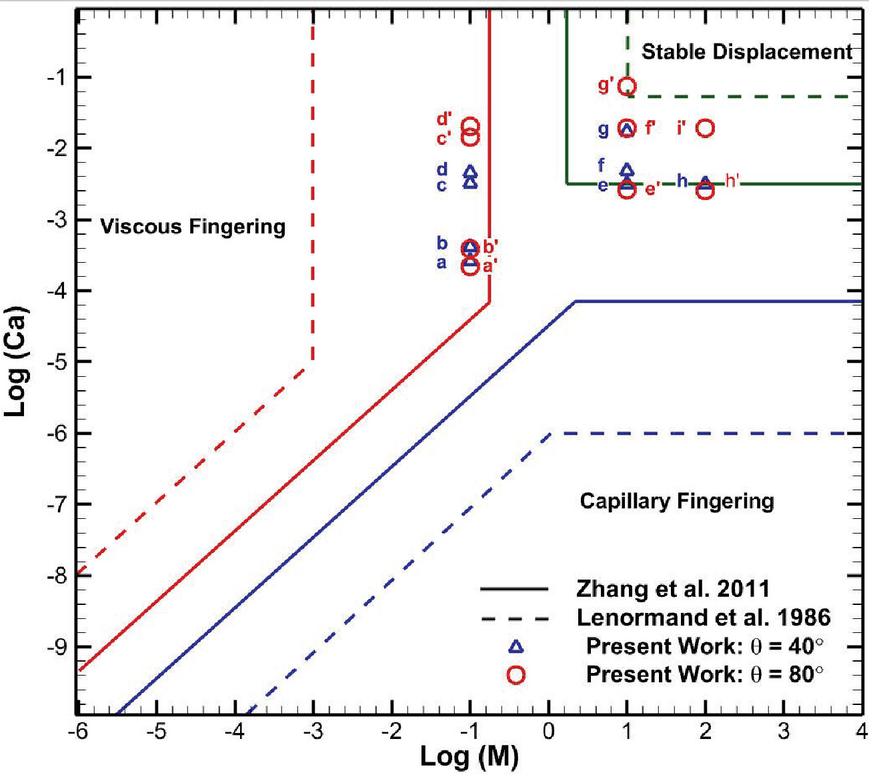
Figure 10 Results obtained for displacement pattern of invading fluid in porous medium by present S-C LBM in comparison with the schematic of phase diagram presented by Zhang et al. [43] and Lenormand et al. [42].

Figure 11 Instantaneous displacement pattern of two immiscible fluids flow through porous medium obtained by present simulations for flow condition and at .
Figure 11 demonstrates the present results for instantaneous two immiscible fluids flow displacement at different times for and at . The invading fluid flow regime has the characteristics of both the stable displacement and the viscous fingering pattern since the fingers are thicker and occupy the neighboring pores. However, in some parts of the domain, the interface of the invading fluid cannot penetrate into the space between the irregular pore-scale geometry. This behavior can be explained by the relation of the threshold pressure :
| (16) |
where is the pore throat diameter. The threshold pressure defines that the invading fluid does not penetrate into a pore area unless the capillary pressure of the fluid exceeds the throat threshold pressure. For a system where the non-wetting fluid contact angle lower than , the throat threshold pressure is positive and resists against the fluid penetration. In the present study shown in Figure 11, the invading fluid has a contact angle . Therefore, the non-wetting fluid only penetrates the pores that their throats are wide enough (larger pore throat diameter ) to reduce the threshold pressure. As a result, the direction of the flow displacement in the porous medium is irregular. In other words, the invading fluid pursues the paths that have the minimum resistance pressure, and this leads to the fingers that are distributed all over the domain.
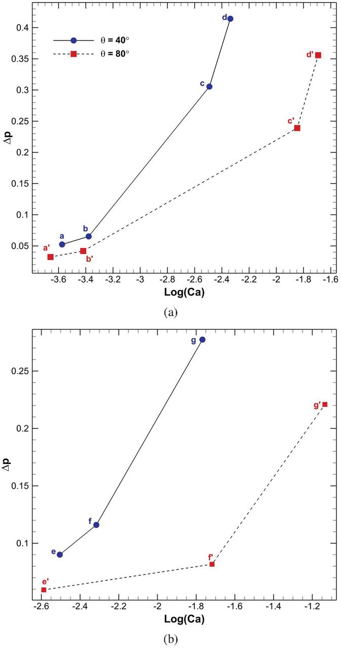
Figure 12 Comparison of pressure difference at the breakthrough moment for flow condition (a) , and (b) with various capillary numbers.
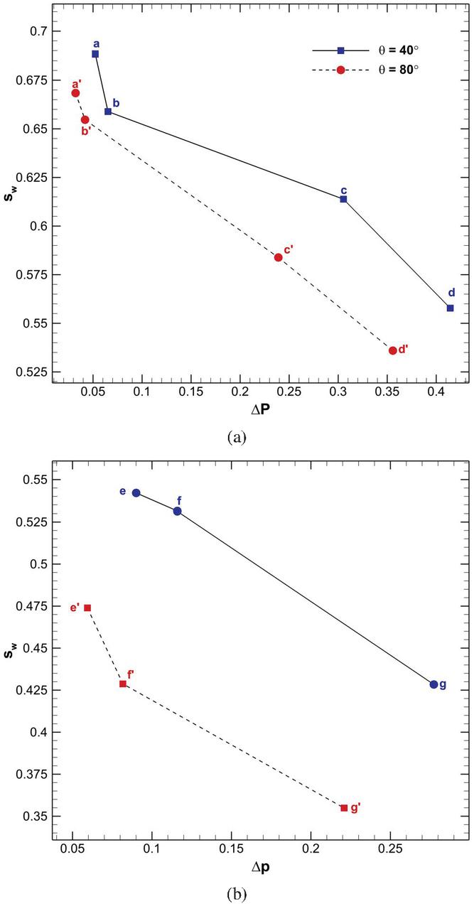
Figure 13 Comparison of wetting fluid saturation versus pressure difference at the breakthrough moment for flow condition (a) , and (b) .
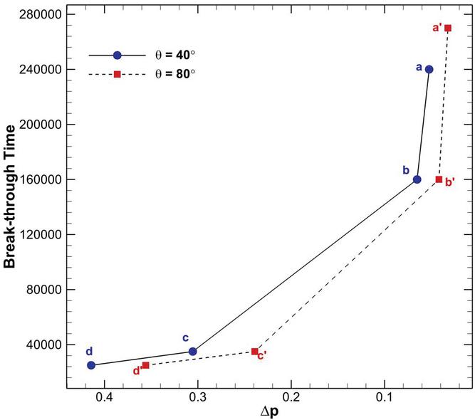
Figure 14 Comparison of breakthrough time versus pressure difference obtained based on present solution at two contact angles considered for porous medium.
The effects of the contact angle, capillary number, and viscosity ratio are studied on the flow characteristics, particularly on the pressure difference between downstream and upstream of the porous medium, , and the wetting fluid saturation, . These properties are computed based on the present solutions when the first finger of the invading fluid touches the outer side of the porous medium for each case, which is called breakthrough [42]. Figure 12 compares the pressure drop versus the capillary number at two contact angles of and for and . This figure shows that by the increment of the capillary number, the pressure difference between the two sides of the porous medium increases. The pressure drop along the porous medium at is more than that of computed for at both the viscosity ratios considered. Also, it is obvious that the difference between the values of obtained for these two contact angles increases at higher capillary numbers. The reason for this flow treatment can be explained by the threshold pressure of the pore throat that resists against the invading fluid when the obstacles of the medium are more hydrophilic. The comparison of the variation of versus capillary number between the results presented in Figure 12(a) and 12(b) demonstrates that the fluid displacement in the stable regime at produces a larger pressure difference in comparison with the viscous fingering regime at . It can be concluded that the main reason for filling the most part of the pore domain with the invading fluid at the stable displacement regime is due to this higher pressure difference between the upstream and downstream of the medium that overcomes the throat threshold pressure.
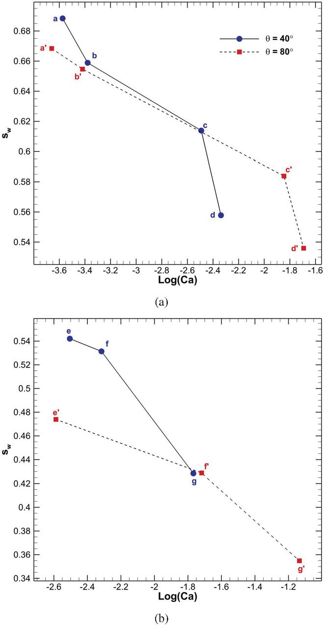
Figure 15 Comparison of wetting fluid saturation at the breakthrough moment for flow condition (a) , and (b) with various capillary numbers.
The pressure difference variation is also related to the wetting fluid saturation in the porous medium. Figure 13 demonstrates the variation of computed based on the present solution for two flow conditions with and . It can be seen that for a given contact angle, a lower saturation of the wetting fluid causes a higher pressure difference. Indeed, the low saturation value indicates that the medium is not filled with the wetting fluid due to the resistance of the pore throat against the penetration of the invading fluid that results in the high-pressure difference. Also, the value of at is larger than its value computed with that is due to the more tendency of the hydrophilic medium to absorb the wetting fluid at . The results presented in Figure 13(b) show that the magnitude of computed for both the contact angles is decreased by the increment of the viscosity ratio from to . This computed result for confirms that the invading fluid penetrates into more pore-scale spaces of the medium at the stable displacement regime.
The present study also shows that the breakthrough time is affected by the pressure difference magnitude along with the porous medium. Figure 14 demonstrates the solution time at the breakthrough condition as a function of the pressure difference for the cases studied in the previous figures. This figure indicates that the breakthrough time increases with the increment of the pressure difference for both the contact angles of and . The value of breakthrough time computed for the lower contact angle, , is higher than that obtained for . Indeed, the intense hydrophilic property of the medium at slows down the penetration of the fingers of the invading fluid into the pores. It should be noted that the lower pressure difference obtained for (see Figure 12) allows the invading fluid to gently occupy the pore domain before reaching the downstream of the medium. In contrast, as seen in Figures 8 and 9, there are more remained patches of the wetting fluid in the porous medium when the contact angle is set to be . Therefore, at this flow condition, the invading fluid can quickly find its way to the downstream in the fingering form rather than distributing over the medium.
Finally, the variation of the wetting fluid saturation is presented as a function of the capillary number in Figure 15 for the flow conditions with and . This figure illustrates that decreases by increasing the capillary number for both the contact angles considered. As the capillary number increases, the viscous force becomes dominant in the domain and pushes the invading fluid through the porous medium. Therefore, the invading fluid pressure overcomes the throat threshold pressure in the most part of the medium and penetrates in larger space of pores that causes significant decrement of the wetting fluid saturation. Also, the wetting fluid saturation for each case with is higher than the corresponding value with that is related to the higher hydrophilic tendency of the medium at lower contact angles.
4 Conclusion
This study is performed to investigate the displacement pattern of two immiscible fluids in a homogeneous porous medium using the numerical computation based on the S-C LBM. Herein, the MRT collision operator with EDM forcing scheme are employed to provide an efficient and numerically stable technique for the simulation of fluid flows through the complex pore-scale geometry. The numerical method is validated by considering different benchmark multicomponent fluid flow problems. The agreement of the present results with the available data in the literature shows the ability and accuracy of the S-C LBM employed for the simulation of interfacial dynamics in contact with the solid surface. Then, the simulation results for the fingering dynamics of the immiscible fluids in the porous medium are presented. This study deals with the viscous fingering and stable displacement regimes. These flow structures are quantified by considering the effect of the capillary number (), dynamic viscosity ratio (), and the contact angle (). The obtained results show that for , the viscous fingering regime appears by driving the invading fluid through the pore structures due to the viscous force and capillary force. However, by increasing the dynamic viscosity ratio and the capillary number, the invading fluid penetrates even in smaller pores and the stable displacement regime occurs. By the increment of the capillary number, the pressure difference between the two sides of the porous medium increases, so that the pressure drop along the domain at is more than that of computed for . The present study shows that the value of wetting fluid saturation at is larger than its value computed with that is due to the more tendency of the hydrophilic medium to absorb the wetting fluid at . Also, it is find that the magnitude of computed for both the contact angles is decreased by the increment of the viscosity ratio from to . The present study demonstrates that the S-C LBM is an efficient and accurate computational method to quantitatively estimate the flow characteristics and interfacial dynamics through the porous medium.
Acknowledgment
The authors would like to thank Shahid Beheshti University for the support of this research.
References
[1] Keehm, Y. Computational rock physics: Transport properties in porous media and applications. 2003.
[2] Yang, J., Multi-scale simulation of multiphase multi-component flow in porous media using the Lattice Boltzmann Method, in Chemical Engineering. 2013, Imperia College London: Imperial College London.
[3] Ezzatabadipour, M. and H. Zahedi, Simulation of a fluid flow and investigation of a permeability-porosity relationship in porous media with random circular obstacles using the curved boundary lattice Boltzmann method. The European Physical Journal Plus, 2018. 133(11).
[4] Ezzatneshan, E. and R. Goharimehr, Study of spontaneous mobility and imbibition of a liquid droplet in contact with fibrous porous media considering wettability effects. Physics of Fluids, 2020. 32(11): p. 113303.
[5] Aidun, C.K. and J.R. Clausen, Lattice-Boltzmann Method for Complex Flows. Annual Review of Fluid Mechanics, 2010. 42(1): pp. 439–472.
[6] Ridha Djebali, M.E.G., Habib Sammouda, Investigation of a side wall heated cavity by using lattice Boltzmann method. European Journal of Computational Mechanics, 2009. 18(2).
[7] Ezzatneshan, E., Implementation of a curved wall- and an absorbing open-boundary condition for the D3Q19 lattice Boltzmann method for simulation of incompressible fluid flows. Scientia Iranica, 2018. 26(4): pp. 2329–2341.
[8] Gunstensen, A.K., et al., Lattice Boltzmann model of immiscible fluids. Physical Review A, 1991. 43(8): pp. 4320–4327.
[9] Shan, X. and H. Chen, Lattice Boltzmann model for simulating flows with multiple phases and components. Physical Review E, 1993. 47(3): pp. 1815–1819.
[10] Shan, X. and H. Chen, Simulation of nonideal gases and liquid-gas phase transitions by the lattice Boltzmann equation. Physical Review E, 1994. 49(4): pp. 2941–2948.
[11] Swift, M.R., W.R. Osborn, and J.M. Yeomans, Lattice Boltzmann simulation of nonideal fluids. Physical Review Letters, 1995. 75(5): pp. 830–833.
[12] He, X., S. Chen, and R. Zhang, A Lattice Boltzmann Scheme for Incompressible Multiphase Flow and Its Application in Simulation of Rayleigh-Taylor Instability. Journal of Computational Physics, 1999. 152(2): pp. 642–663.
[13] Ezzatneshan, E., Study of surface wettability effect on cavitation inception by implementation of the lattice Boltzmann method. Physics of Fluids, 2017. 29(11).
[14] Chen, S. and G.D. Doolen, Lattice Boltzmann Method for Fluid Flows. Annual Review of Fluid Mechanics, 2002. 30(1): pp. 329–364.
[15] McCracken, M.E. and J. Abraham, Multiple-relaxation-time lattice-Boltzmann model for multiphase flow. Phys Rev E Stat Nonlin Soft Matter Phys, 2005. 71(3 Pt 2B): p. 036701.
[16] Ezzatneshan, E., Comparative study of the lattice Boltzmann collision models for simulation of incompressible fluid flows. Mathematics and Computers in Simulation, 2019. 156: pp. 158–177.
[17] Kuzmin, A., A.A. Mohamad, and S. Succi, Multi-Relaxation Time Lattice Boltzmann Model for Multiphase Flows. International Journal of Modern Physics C, 2008. 19(06): pp. 875–902.
[18] Yu, Z. and L.S. Fan, Multirelaxation-time interaction-potential-based lattice Boltzmann model for two-phase flow. Phys Rev E Stat Nonlin Soft Matter Phys, 2010. 82(4 Pt 2): p. 046708.
[19] Zhang, D., K. Papadikis, and S. Gu, Advances in Water Resources A lattice Boltzmann study on the impact of the geometrical properties of porous media on the steady state relative permeabilities on two-phase immiscible flows. Advances in Water Resources, 2016. 95: pp. 61–79.
[20] Bakhshian, S., S.A. Hosseini, and N. Shokri, Pore-scale characteristics of multiphase flow in heterogeneous porous media using the lattice Boltzmann method. Sci Rep, 2019. 9(1): p. 3377.
[21] Kupershtokh, A.L., D.A. Medvedev, and D.I. Karpov, On equations of state in a lattice Boltzmann method. Computers & Mathematics with Applications, 2009. 58(5): pp. 965–974.
[22] Ezzatneshan, E. and R. Goharimehr, A Pseudopotential Lattice Boltzmann Method for Simulation of Two-Phase Flow Transport in Porous Medium at High-Density and High–Viscosity Ratios. Geofluids, 2021. 2021: pp. 1–18.
[23] Pan, C., L.-S. Luo, and C.T. Miller, An evaluation of lattice Boltzmann schemes for porous medium flow simulation. Computers \& Fluids, 2006. 35(8-9): pp. 898–909.
[24] Huang, H., J.J. Huang, and X.Y. Lu, Study of immiscible displacements in porous media using a color-gradient-based multiphase lattice Boltzmann method. Computers and Fluids, 2014. 93: pp. 164–172.
[25] Gao, C., R.-N. Xu, and P.-X. Jiang, Pore-scale numerical investigations of fluid flow in porous media using lattice Boltzmann method. International Journal of Numerical Methods for Heat \& Fluid Flow, 2015. 25(8): pp. 1957–1977.
[26] Xu, M. and H. Liu, Prediction of immiscible two-phase flow properties in a two-dimensional Berea sandstone using the pore-scale lattice Boltzmann simulation. Eur Phys J E Soft Matter, 2018. 41(10): p. 124.
[27] Ju, Y., et al., Effects of pore characteristics on water-oil two-phase displacement in non-homogeneous pore structures: A pore-scale lattice Boltzmann model considering various fluid density ratios. International Journal of Engineering Science, 2020. 154: p. 103343.
[28] Kupershtokh, A.L., D.A. Medvedev, and D.I. Karpov, On equations of state in a lattice Boltzmann method. Computers and Mathematics with Applications, 2009. 58: pp. 965–974.
[29] Luo, L.-S., Theory of the lattice Boltzmann method: Lattice Boltzmann models for nonideal gases. Physical Review E, 2000. 62(4): pp. 4982–4996.
[30] Huang, H., et al., Proposed approximation for contact angles in Shan-and-Chen-type multicomponent multiphase lattice Boltzmann models. Physical Review E, 2007. 76(6): p. 066701.
[31] Martys, N.S. and H. Chen, Simulation of multicomponent fluids in complex three-dimensional geometries by the lattice Boltzmann method. Physical Review E, 1996. 53(1): pp. 743–750.
[32] Kang, Q., D. Zhang, and S. Chen, Displacement of a two-dimensional immiscible droplet in a channel. Physics of Fluids, 2002. 14(9): pp. 3203–3214.
[33] Pan, C., M. Hilpert, and C.T. Miller, Lattice-Boltzmann simulation of two-phase flow in porous media. Water Resources Research, 2004. 40(1): pp. 1–14.
[34] Baakeem, S.S., S.A. Bawazeer, and A.A. Mohamad, A Novel Approach of Unit Conversion in the Lattice Boltzmann Method. Applied Sciences, 2021. 11(14): p. 6386.
[35] Huang, H., et al., Proposed approximation for contact angles in Shan-and-Chen-type multicomponent multiphase lattice Boltzmann models. Phys Rev E Stat Nonlin Soft Matter Phys, 2007. 76(6 Pt 2): p. 066701.
[36] Schaap, M.G., et al., Comparison of pressure-saturation characteristics derived from computed tomography and lattice Boltzmann simulations. Water Resources Research, 2007. 43(12).
[37] Weil, K.G., J. S. Rowlinson and B. Widom: Molecular Theory of Capillarity, Clarendon Press, Oxford 1982. 327 Seiten, Preis: \pounds 30,-. Berichte der Bunsengesellschaft f \u r physikalische Chemie, 1984. 88(6): pp. 586–586.
[38] Liu, H., et al., Multiphase lattice Boltzmann simulations for porous media applications. Computational Geosciences, 2015. 20(4): pp. 777–805.
[39] Zhang, B., et al., Beyond Cassie equation: local structure of heterogeneous surfaces determines the contact angles of microdroplets. Sci Rep, 2014. 4(1): p. 5822.
[40] Washburn, E.W., The Dynamics of Capillary Flow. Physical Review, 1921. 17(3): pp. 273–283.
[41] Chibbaro, S., Capillary filling with pseudo-potential binary Lattice-Boltzmann model. Eur Phys J E Soft Matter, 2008. 27(1): pp. 99–106.
[42] Lenormand, R., E. Touboul, and C. Zarcone, Numerical models and experiments on immiscible displacements in porous media. Journal of Fluid Mechanics, 2006. 189(1988): pp. 165–187.
[43] Zhang, C., et al., Influence of Viscous and Capillary Forces on Immiscible Fluid Displacement: Pore-Scale Experimental Study in a Water-Wet Micromodel Demonstrating Viscous and Capillary Fingering. Energy & Fuels, 2011. 25(8): pp. 3493–3505.
[44] Liu, H., Y. Zhang, and A.J. Valocchi, Lattice Boltzmann simulation of immiscible fluid displacement in porous media: Homogeneous versus heterogeneous pore network. Physics of Fluids, 2015. 27(5): p. 052103.
Biographies

Eslam Ezzatneshan is assistant professor of Aerospace Engineering in the Department of New Technologies and Aerospace Engineering at the Shahid Beheshti University. He received PhD’s degree from the Sharif University of Technology, and did his post-doctoral research at the Chalmers University of Technology. Dr. Ezzatneshan’s areas of expertise include multiphase flows (cavitation phenomena in isothermal and cryogenic fluids, bubbles and droplets dynamics, flow transport through porous media) and computational aerodynamics and hydrodynamics. Dr. Ezzatneshan leads a multidisciplinary research group in the Multiphase Flows Laboratory (MPFL) which has collaborations with experimentalists and industry to have truly interdisciplinary research and training in modern science and engineering.

Reza Goharimehr received bachelor’s degree in Mechanical Engineering from IAUN in 2015 and his master’s degree in Aerospace Engineering from Shahid Beheshti University in 2019. Since 2017, Reza has started to pursue his research with a specific focus on multiphase flows and the development of numerical solvers for simulation flow transport through complex geometries.
European Journal of Computational Mechanics, Vol. 30_4-6,, 275–304.
doi: 10.13052/ejcm2642-2085.30461
© 2021 River Publishers