Understanding Cohesive Law Parameters in Ductile Fracture Initiation and Propagation
Mariana R. R. Seabra* and José M. A. César de Sá
University of Porto, Portugal
E-mail: marianas@fe.up.pt
Corresponding Author
Received 24 May 2021; Accepted 26 May 2021; Publication 20 July 2021
Abstract
Continuum Damage Mechanics is successfully employed to describe the behaviour of metallic materials up to the onset of fracture. Nevertheless, on its own, it is not able to accurately trace discrete crack paths. In this contribution, Continuous Damage Mechanics is combined with the XFEM and a Cohesive Law to allow the full simulation of a ductile fracture process. In particular, the Cohesive Law assures an energetically consistent transition from damage to crack for critical damage values lower than one. Moreover, a novel interpretation is given to the parameters of the cohesive law. A fitting method derived directly from the damage model is proposed for these parameters, avoiding additional experimental characterization.
Keywords: Ductile fracture, XFEM, cohesive law.
1 Introduction
Ductile fracture is the main failure mechanism in metals and therefore a critical scientific and industrial concern. Although much has been achieved in the field, many open questions remain due to the complexity of the phenomenon. In particular, simulating transition from continuous damage to discrete fracture is still a challenging issue.
Ductile failure is characterized by localized plastic flow and by formation and growth micro-voids within the material, which eventually coalesce to form micro-cracks and subsequent macro-cracks [1]. As a result, in general, ductile fracture modelling requires a three step approach, namely, a description of the material behaviour prior to crack formation, a criterion for the onset of cracking and an adequate methodology to trace crack growth. Regarding the first step, two large families of models evolved, namely, Micro-Mechanical models and Continuous Damage Models (CDM).
Micro-Mechanical models aim bringing a realistic description of the ductile fracture process in terms of void nucleation, growth and coalescence. They were primarily developed by Gurson [2] and submitted to further extensions. In particular, Tvergaard and Needleman proposed a better representation of void growth and coalescence, which became known as Gurson-Tvergaard-Needleman (GTN) model [3]. Nevertheless, GTN models remain phenomenological and the experimental characterization of its parameters is not straightforward.
On the other hand, CDM are developed on a thermodynamically consistent framework, where material degradation is evaluated through the introduction of a damage variable. This damage concept was introduced by Kachanov [4] and Rabotnov [5] and incorporated in later theories as an internal variablle. Thus, micro-mechanical phenomena are dealt with in an averaging way. Important contributions for the full establishment of CDM are due to Lemaitre [6, 7, 8] and Chaboche [9, 10], in which damage and plasticity are strongly coupled. CDM has the advantage of being consistent with fundamental physical principles.
Both GTN and CDM have been extensively employed and compared and good reviews are available in the literature, such as [1, 11, 12]. Nevertheless, even in a numerical context, both approaches are unable to represent surface decohesion and propagation of cracks in a structure. In order to overcome this limitation, GTN and CDM have been combined with different methodologies such as remeshing [13, 14, 15, 16, 17, 18, 19], element deletion technique [20, 21], smeared crack model [22] or the eXtended Finite Element Method (XFEM) [23, 24]. This last option has been developed by the authors of this paper in the context of CDM in reference [23], in which crack initiation and propagation are governed by the evolution of the continuous damage variable. One of the main advantages of the proposed approach is the possibility of crack growth independently from the finite element mesh, in a path not necessarily known a priori. Furthermore, the model was also able to handle several fracture locations in a single problem. In brief, in CDM, the damage variable, is considered 0 for a virgin material and 1 for a fully damaged material. Therefore, in the developed model crack was initiated when a certain critical damage, , was achieved.
In theory, to ensure thermodynamical consistency in the model in use, the transition from damage to fracture should occur when the material is fully degraded, that is, for . At this point the damage energy release would be equivalent to the energy necessary to create a crack surface [25]. However, setting the damage value to 1 leads to a singularity in the continuum equations, with its natural numerical consequences. Thus, following previous experimental work, critical damage is usually located between 0.2 and 0.5, leaving and energy loss gap which should be fulfilled.
One possible solution to this problem is to add a cohesive law to the original model. Previously, it was considered that once a crack is introduced, the newly formed surfaces no longer interact, that is, the cracks were considered traction-free. A cohesive law is a traction-displacement relation, which models the interaction between the two surfaces of a crack [26, 27, 28, 29, 30]. From the micro-mechanical point view, it may be interpreted as material which is not fully damaged and, consequently some connection between the two crack surfaces remains.
In terms of macro-modelling, the transition from damage to fracture for critical damage values lower than one could be compensated by the cohesive law. This concept has been previously applied by Cazes et all. [31, 32], in a formulation that does not require a pre-defined shape for a cohesive law but in which the location of the crack must be known in advance. As additional disadvantage, the model was only fully developed for 1D cases. In this work, a shape for the cohesive law is assumed but its parameters are fitted following energetic considerations, which constitutes one of the main novelties of this approach. Here, the parameters which define the cohesive law are not regarded as characteristic material parameters, but rather numerical parameters, which are numerically fit to approximate an energetically consistent transition from damage to fracture. Our approach is conceptually related to the equivalent crack concept developed by Mazars and Pijaudier-Cabot [25]. Nevertheless, contrary to these authors, we propose a global energetic balance, rather than a local energy balance in the vicinity of the crack tip. Furthermore, our approach does not require the use of quantities derived from Linear Elastic Fracture Mechanics (LEFM), such as the characteristic fracture energy. As a result, the present model incorporates CDM, XFEM and a cohesive law, whose parameters are numerically fit directly from the damage model. Consequently, additional tedious experimental work that would be necessary to characterize the cohesive law is avoided.
A model incorporating a cohesive law through XFEM in the GTN model has been proposed in the literature [33]. Nonetheless, to the knowledge of the authors is the first time that such a model is developed in the context of CDM. Moreover, an interpretation of the parameters of the proposed cohesive law is also presented in the context of CDM, rather than in the traditional LEFM context.
In this way, in Section 2 the theoretical bases of the proposed methodology are set. As this work is an extension of a previous publication, basic CDM principles and XFEM implementation are summarized, while attention is devoted to Cohesive law formulation. In Section 3 the main achievements of the proposed methodology are illustrated through some numerical examples. Finally, in Section 4 the main conclusions of this paper are outlined.
2 Methods
2.1 Continuous Damage Model
The present work is an extension of a previously published model. Hence, the employed material model and the basic XFEM implementation are only briefly described. Interested readers should consult reference [23] for more details. Thus, following the CDM framework proposed by Lemaître, [8], the free energy, , for an isothermal process, is assumed to be a function of a set of internal variables [34] as:
| (1) |
where is the Cauchy-Green tensor, calculated from the deformation gradient, , as
| (2) |
is the covariant plastic metric, is the isotropic hardening variable and is the damage variable. In turn, assuming multiplicative decomposition of the Cauchy-Green tensor [35, 36, 37], the mixed variant elastic strain measure may be obtained as:
| (3) |
The spatial configuration of the elastic left Cauchy-Green tensor, which is useful to define the plastic flow, follows as:
| (4) |
Finally, from the free energy it is possible to derive the variables associated to plastic flow, isotropic hardening and damage:
| (5) | |
| (6) | |
| (7) |
In the above equations, represents the Kirchhoff stress tensor, represents the thermodynamic forces conjugated with isotropic hardening, stands for damage energy release rate and for mass density. The Green-Lagrange strain tensor, , and the second Piola-Kirchhoff stress, , which are required in the equilibrium equation terms, are defined as
| (8) | |
| (9) |
where represents the identity tensor.
Additionally, a complementary energy dissipation potential, , must be defined, as ductile damage occurs simultaneously with large plastic strains. It is specially convenient to consider both effects in a decoupled way defining as:
| (10) |
where and are the energy potentials associated with plasticity and damage, respectively. As a result, the evolution equations of the constitutive model may be derived once these potentials are defined. For the plastic part, assuming the strain equivalence principle [8], the von Mises yield function may be adopted:
| (11) |
where is the uni-axial yield stress. For the damage dissipation potential the following function, based on the work of Lemaitre [8], is considered:
| (12) |
where and are scalar material parameters associated with damage evolution. Finally, making use of the normality rule it is possible to determine the evolution equations:
| (13) | |
| (14) | |
| (15) |
where represents the spatial velocity Lie derivative and is the plastic multiplier.
The presented model has been proven to successfully describe the behaviour of ductile metals, at least until the onset of cracking [12]. Nevertheless, when implemented on a finite element framework it suffers from pathological mesh dependence [38]. Hence, it has been regularized using a non-local integral formulation, whose details are described in reference [23]. Moreover, in the aforementioned work, to accurately capture crack growth path, a discrete traction-free crack was introduced once the damage variable reached a critical value. In this work, traction-free cracks are replaced by cohesive cracks, following the formulation described on next subsection.
2.2 General Cohesive Law Formulation
In a domain containing a cohesive crack, the stress field must be related not only to external loading but also to cohesive tractions, which are active in the cohesive zone. An additional condition for the cohesive interface must be satisfied together with the equilibrium equation, as described in the following paragraph.
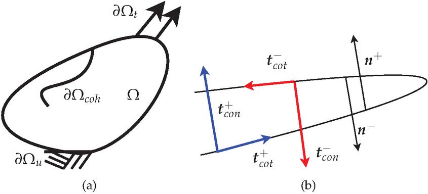
Figure 1 (a) Body containing a cohesive crack. (b) Detail of the cohesive crack.
Considering a body containing a cohesive crack, represented in Figure 1, the equilibrium equation for the static case is given by:
| (16) |
and the applied tractions, , must satisfy
| (17) |
In the cohesive zone, considering normal and tangential interactions as represented in Figure 1(b), the cohesive tractions, and , are given by:
| (18) |
and
| (19) |
where and are the normal vectors to the crack surfaces, as illustrated in Figure 1(b). The cohesive tractions are considered to be a function of the crack opening, , defined as:
| (20) |
Equation 20 may be split in a normal component and a tangential component as follows:
| (21) |
where is a vector perpendicular to and, consequently:
| (22) |
Finally, due to the additional condition introduced by the cohesive zone interface, the weak form of the equilibrium equation is given by:
| (23) |
for an admissible virtual displacement . At this point, a constitutive law for the cohesive zone should be formally defined. Shape and parameters of such cohesive law are often related to the micro-mechanical mechanisms underlying the so-called fracture process zone, that is, in the region where fracture is likely to happen. Particle-matrix decohesion, void growth and coalescence or solute segregation are examples of such mechanisms, which subsequently give rise to macro-crack propagation.
In general, when the cohesive zone model is used to describe the complete fracture process, the effect of micro-mechanical processes prior to material separation is described by an increasing traction across the interface. The maximum traction, , triggers the initiation of material separation and consequently, the traction decreases and eventually vanishes allowing a complete decohesion [28, 39, 29, 30, 40]. To accommodate those physical features, cohesive traction-crack opening relation may be mathematically expressed by a bilinear or a polynomial/exponential type law as represented in Figure 2 [29, 30, 40].
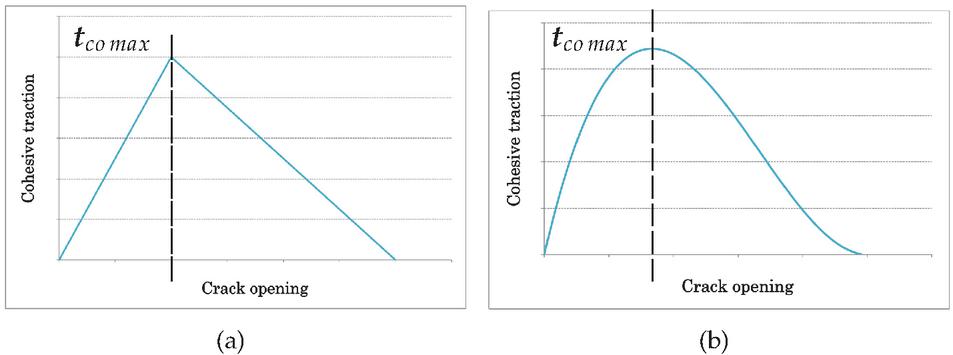
Figure 2 (a) Bilinear cohesive law. (b) Polynomial cohesive law.
In the case of macroscopically homogeneous materials, which is the often the case with ductile metals, the shape of the cohesive law is regarded to be of secondary importance [41]. Additionally, in terms of a numerical simulation, the effect of linear or exponential laws in the global material response is qualitatively similar.
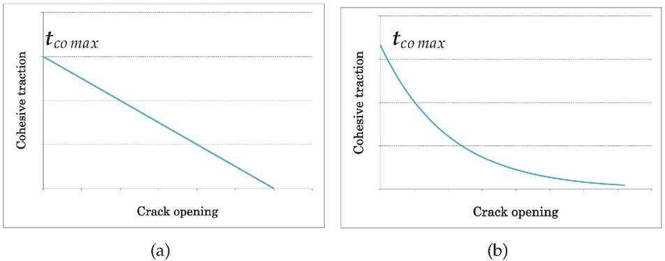
Figure 3 (a) Linear cohesive law. (b) Exponential cohesive law.
When the onset of fracture is triggered with some additional criterion, like in this work, where macro-cracks are initiated when damage reaches a critical value, the first part of the cohesive law vanishes. The cohesive law is only used to model the interaction of the two surfaces of a crack until full material separation. Considering in particular ductile metals, linear type and exponential type of cohesive laws (Figure 3) are the mostly used [28, 39, 30, 40, 41]. In both types of laws, the maximum cohesive traction occurs at the crack tip and its influence decreases away from it. The main difference is that, in the linear case, there is a certain crack opening threshold from which the cohesive law stops acting, while in the exponential case the cohesive law is permanently active (although, after a certain crack opening value its influence is negligible). Hence, in this work an exponential type of law is adopted and may expressed in the general form:
| (24) |
and therefore is characterised by two parameters, the maximum cohesive tension, , discussed in the previous paragraphs and the shape factor, . Therefore, normal and tangential components of the cohesive tension are considered as follows:
| (25) |
where and represent the maximum cohesive tension and and are shape factors of the cohesive law for the normal and tangential components, respectively. Alternatively, an exponential cohesive law may be characterized by the maximum cohesive traction and the associated energy, , which corresponds to the area under the cohesive traction-crack opening curve. However both descriptions are equivalent.
2.3 Characterization of the Cohesive Law Parameters
Traditionally the parameters of the cohesive law are considered to be characteristic of a certain material and are often related to the fracture energy, , defined as the amount of energy dissipated in the creation of an unit traction-free crack. Here we proposed a novel approach, in which the parameters of the cohesive law are not considered characteristic material parameters, but rather numerical parameters derivable from the damage model. The proposed methodology is conceptually related to previous achievements in the literature, however materializes in a new way, avoiding the use of parameters stemming from LEFM, which may not be adequate in a context of generalized plastic deformation. In the following paragraphs, the relation with these previous developments is described.
A straighforward way of characterizing a cohesive law was presented by Alfaiate et al. [42]. In this work, the normal cohesive tension is given by the following expression:
| (26) |
where is the initial tensile strength of the undamaged material. As these parameters, especially are obtained through LEFM considerations, they may not be adequate for ductile fracture. In fact, even the extensions of LEFM to include plastic effects, such as the J-Integral, fail in describing the fracture process in materials which deform substantially in the plastic regime.
Another interesting approach may be found in the work of Tvergaard and Hutchinson [28], who studied ductile fracture using a Gurson-type model. There, it was proposed that the energy necessary to create a macro-crack, , is a function the energy required to grow and coalesce the voids in the material, , that is
| (27) |
with
| (28) |
In equation 28 is the yield strength and is the average void fraction. The authors also observed that the intensive plastic strain in the vicinity of the crack tip accelerates the nucleation of additional voids, which consequently has the potential of significantly lowering the relative crack resistance. The explicit form of the function is simultaneously dependent on the plastic strain and on the void fraction, resulting in a traction-separation law equally dependent on these phenomena. Establishing a comparison between the Gurson and the Lemaitre model, it follows that, in the later, the parameters of the cohesive law should somehow be related to the damage variable, as well as to plastic strain. Drawing from these two approaches, a first estimate for the maximum cohesive traction , may be given by:
| (29) |
where is the maximum yield traction (a property characteristic of the material) and therefore the cohesive law is related to plastic straining and damage. In terms of the shape factor, , as it influences the shape of the cohesive law, its value should ensure that the effects of the cohesive zone are noticeable in the final response of the component. In Figure 4, the general influence of the parameters in the cohesive tension-crack opening curve is depicted.
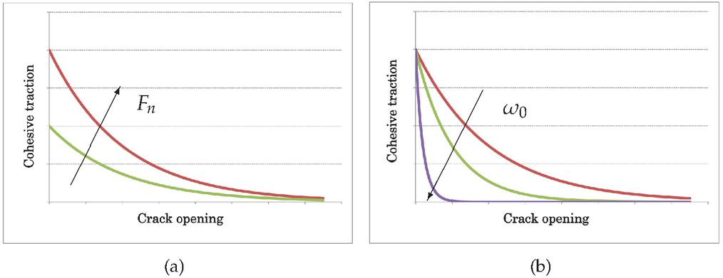
Figure 4 Changes in the cohesive response in function of (a) (b) .
Nevertheless, as the cohesive law is inserted with the objective of making the transition from damage to fracture energetically consistent, this first approximation should be optimized through an energy equivalence. Different forms of such equivalence have been proposed in the literature.
Early crack propagation models, based on LEFM concepts assumed that there is a certain amount of dissipated energy, which is material-specific and is responsible for a certain crack extension. Fracture was triggered by a single parameter such as Griffith fracture energy or stress intensity factor. Even extensions of this theories to include crack tip plasticity still rely on a single parameter and consider that the total amount of dissipated energy in a deformation process is used to propagate cracks [43, 30].
In materials which exhibit substantial deformations prior to crack growth at least two energy consuming processes should be considered, one related to plastic deformation and another related to progressive material degradation, that is, related to damage. In this context, Mazars and Pijaudier-Cabot [25] developed the equivalent crack concept, in which the damage energy release rate is equivalent to the crack surface energy, as follows:
| (30) |
In Equation 30 is the overall volume of the structure, is the damage energy release rate (as defined in 2), is the damage variable, is the fracture energy, and is the area of the crack. One of the main limitations of this approach is that requires the value of the fracture energy, which is a parameter derived from the LEFM and its applicability in a ductile fracture context may be questionable.
Keeping the concept of the above approaches, it is possible to avoid the incorporation of additional material properties by considering a global energy balance in the whole structure, rather than a local energy balance associated to the fracture energy. In terms of a finite element implementation, a local balance may be ambiguous in terms of the elements which should contribute for the energy balance. That is, should all the elements which reached critical damage in a certain region be considered for such an energy balance, or only the elements which contain the crack. In addition, the direct energy transfer from the damaged volume to the crack surface admits that the micro-mechanical damage processes in that volume stops evolving and that all the energy stored in the micro-structure is transmitted to the dominant macro-crack, which is not necessarily true.
Thus, contrary to the previous solutions, and departing from a global evaluation of the strain energy, as follows:
| (31) |
a function, , is constructed for traction-free cracks, in order to approximate the value of . Then, departing from a certain value of , a cohesive law will be added in order to meet the condition:
| (32) |
In practice, for a given domain, several numerical simulations are performed, considering different critical damage values, that is, and so forth. In this way, it is possible to construct a function relating the strain energy and the critical damage. Next, by interpolation, which may be of different types, such as polynomial or exponential, the value of the strain energy corresponding to is determined. Finally, a lower value of critical damage is selected, and the parameters of the cohesive law are fit in order to meet the same value of strain energy. This process is clarified throughout the numerical examples displayed on Section 3. The presence of the cohesive law actually compensates for a transition from damage to fracture for critical damage values lower than one. Before moving to the numerical examples, this section devoted to methods is finalized by given a brief note on the XFEM implementation.
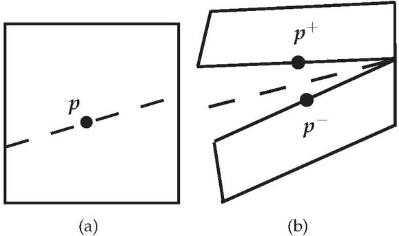
Figure 5 (a) Point on the crack surface. (b) Images of point .
2.4 Brief Note on the XFEM Implementation
In a problem where cracks are modelled with the XFEM, the implementation of a cohesive law is straightforward [44]. A point , located exactly on the crack, may be considered to have two images when the crack opens: on one crack surface and on the other, as illustrated in Figure 5. For cracks represented through the XFEM, the difference between and lays in the value of the Heaviside function , that is:
| (33) |
Consequently, the crack opening at point is given by:
| (34) |
or by
| (35) |
for located in a split or a tip element, respectively. A slipt element is an element totally crossed by a crack, whereas a tip element is only partially crossed by a crack. Consequently, and are the additional degrees of freedom associated with split and tip elements, respectively. Besides the Heaviside function, tip elements require an additional function, , employed precisely to model the terminus of the crack, and defined in terms of element local coordinates, ,as follows:
| (36) |
In terms of numerical integration, two Gauss points per crack segment, per element are employed, as schematically illustrated in Figure 6.
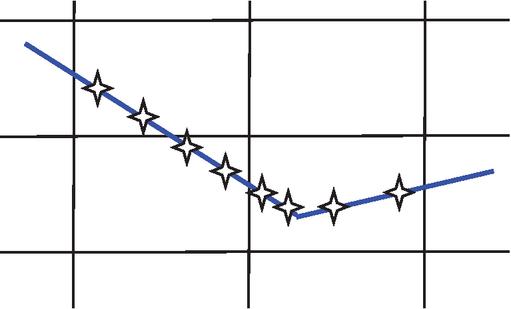
Figure 6 Gauss points used in the integration of a cohesive law.
Having defined the main components of the proposed ductile fracture model, numerical results are displayed in next section.
3 Results
In this section the methodology developed in the previous section is illustrated through some numerical examples. Firstly, it is intended to investigate the influence of the presence of a cohesive law in crack initiation and propagation. Thus, in the first example, a first guess for the cohesive law parameters is employed and results are compared with the model containing a traction-free crack presented in reference [23]. Afterwards, in a second set of numerical examples, the full scheme developed to fit the cohesive law parameters is illustrated. It should be noticed that the finite element formulation is prepared to deal simultaneously with a normal and a tangential cohesive laws. However, as in the problems addressed, the influence of the normal cohesive law is dominant, the tangential part is neglected.
3.1 Transition from Damage to Fracture in a Plain Strain Specimen
This first example addresses transition from damage to fracture in a plain strain specimen. A first estimate for the parameters of the cohesive law is employed, as described in the previous section:
| (37) |
where is chosen in such a way , which corresponds to . In terms of , as it influences the shape of the cohesive law, its value should ensure that the effects of the cohesive zone are noticeable in the final response of the component.
The plane strain specimen is illustrated in Figure 7, which was previously analysed in the context of traction-free cracks. In the same figure it is represented the finite element mesh employed, which has a 2205 elements. Material properties are summarized in Table 1.
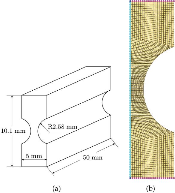
Figure 7 (a) Plane strain specimen (b) FEM mesh.
Table 1 Material properties of the cracked plate
| Property | Value |
| Elastic modulus | |
| Poisson’s ratio | |
| Damage exponent | |
| Damage denominator | |
| Hardening function | |
| Critical damage | |
| Non-local length |
In the first analysis critical damage has the value of . The reaction force-applied displacement curve of a traction-free crack is compared with the one containing a cohesive crack, considering and . Results are displayed in Figure 8.
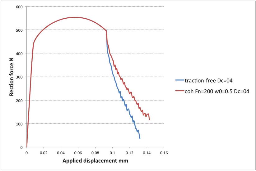
Figure 8 Reaction force-applied displacement curves.
The cohesive law ensures a smoother transition from damage to fracture and a smoother crack propagation, as a result the strain energy under the reaction force-applied displacement curve increases. Comparing the results with the case of a traction-free crack where , it can be observed in Figure 9 that the curve corresponding to may be approached by the curve enhanced by the cohesive law. This fact suggests that the curve corresponding to the traction free crack could be approached by setting the cohesive parameters to the right values.
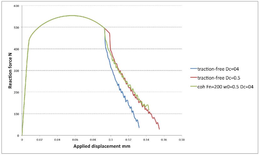
Figure 9 Reaction force-applied displacement curves and respective influence of the cohesive law.
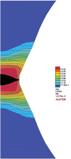
Figure 10 Final crack opening in the plain strain specimen and respective damage contours.
To finalize this example, the final crack opening is illustrated in Figure 10 and crack evolution is illustrated in Figure 11 where, however, the effect of the cohesive law is not so significant. The crack growth speed is still higher for combined with the cohesive law than for . Depending on the particular application, it may be more important to have an accurate prediction of the load level/applied displacement at which the failure of the component happens or an accurate prediction of the crack length evolution. The important conclusion is that simulations with high critical damage may be approached by simulations with lower critical damage, combined with a cohesive law.
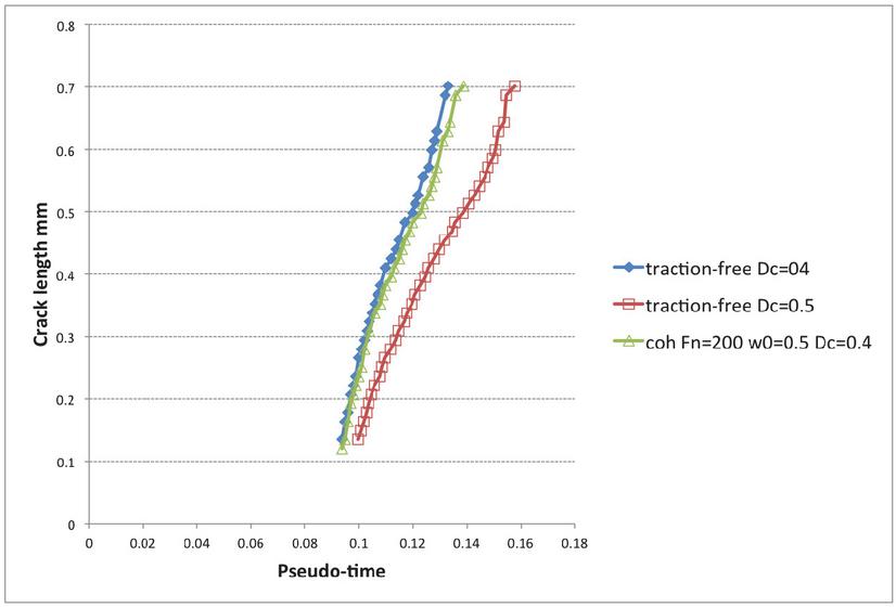
Figure 11 Influence of the cohesive law in the evolution of the crack length.
3.2 Calibration of the Parameters of the Cohesive Law: Plain Strain Problem
Now the previous example is extended to illustrate the full approach towards an energetically consistent transition from damage to fracture. Firstly, the values of the strain energy involved in each one of the cases presented in the previous example, namely traction-free crack with , traction-free crack with and cohesive crack with are computed and displayed in Table 2.
Table 2 Strain energy for
| Case | Strain Energy – J |
| traction-free | 101.4 |
| cohesive | 121.7 |
| traction-free | 121.8 |
In terms of energy balance, the introduction of a cohesive law is indeed equivalent to a rise in the critical damage value. To emphasise this fact, the influence of the cohesive law for and are illustrated in Figure 12. The respective values of the strain energy may be found in Table 3. Choosing the values and , the curve corresponding to a traction-free case with is very well approximated. In terms of energy balance, the choice and also produces good results, but the crack propagation phase is over-smoothed, suggesting that approximations using lower values of the strain energy are preferable to approximations using higher values of the strain energy.
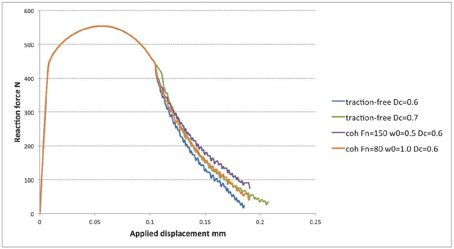
Figure 12 Reaction force-applied displacement curves and respective influence of the cohesive law.
Table 3 Strain energy for
| Case | Strain Energy – J |
| traction-free | 132.4 |
| traction-free | 139.6 |
| cohesive , , | 136.4 |
| cohesive , , | 140.1 |
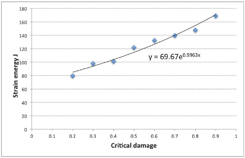
Figure 13 Strain energy as a function of the critical damage. Correlation factor: .
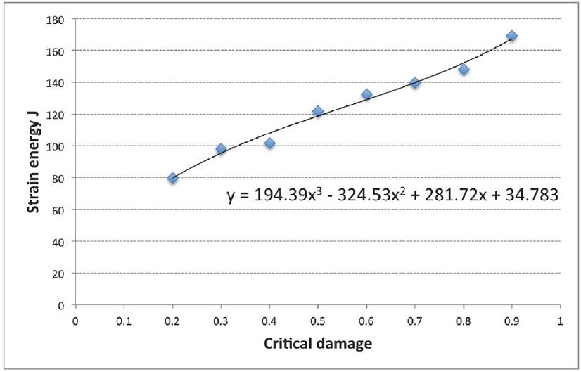
Figure 14 Strain energy as a function of the critical damage. Correlation factor: .
To achieve the energetically consistent transition from damage to fracture, one must determine the strain energy for . In Figures 13 and 14 the strain energy as a function of the critical damage value is represented, together with two alternative fittings: an exponential function of the type and a polynomial function as . The coefficients defining each function were determined using the least-squares method. Using the exponential function the strains energy value is , while using the polynomial function . The proximity of the two values suggests that the real value of should be of this order of magnitude. Therefore, departing from a critical damage value of , a cohesive law was added in order to meet .
The best fit is obtained setting the parameters of the cohesive law to and . The strain energy obtained is , which is quite close to the expected value. In Figure 15 it is possible to observe the difference between the traction-free and the cohesive reaction force-applied displacement curves.
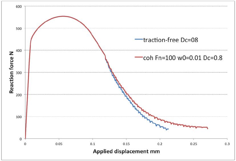
Figure 15 Reaction force-applied displacement curves and respective influence of the cohesive law.
3.3 Calibration of the Parameters of the Cohesive Law: Axisymmetric Problem
The proposed methodology for energetically consistent transition from damage to fracture is now analysed for an axisymmetric example. The specimen is represented in Figure 16, along with the corresponding finite element mesh, with 2883 elements. The material properties are summarized in Table 4. The final crack opening is depicted in Figure 17.
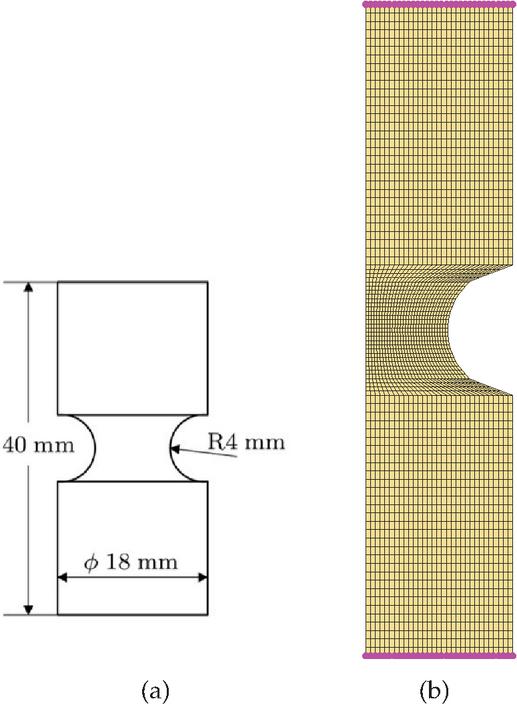
Figure 16 (a) Plane strain specimen (b) FEM mesh.
Table 4 Material properties of the axisymmetric notched specimen
| Property | Value |
| Elastic modulus | |
| Poisson’s ratio | |
| Damage exponent | |
| Damage denominator | |
| Hardening function | |
| Non-local length |
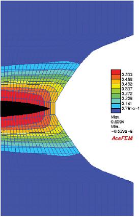
Figure 17 Final crack opening in the axisymmetric strain specimen and respective damage contours.
In this example, the strain energy is also expressed as a function of critical damage, however, observing the distribution pattern, a logarithmic fitting seams more adequate than the exponential fitting used in the previous example. Therefore, a fitting considering a logarithmic function of the type and a fitting considering a polynomial function as are respectively displayed in Figures 18 and 19 . Accordingly it follows that or . Once more the two values are relatively close and an attempt to reach is depicted in Figure 20.
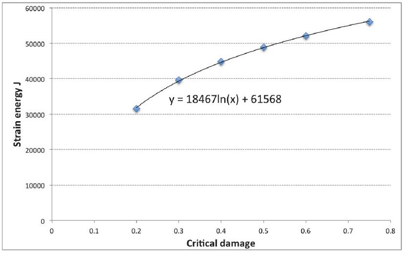
Figure 18 Strain energy as a function of the critical damage. Correlation factor: .
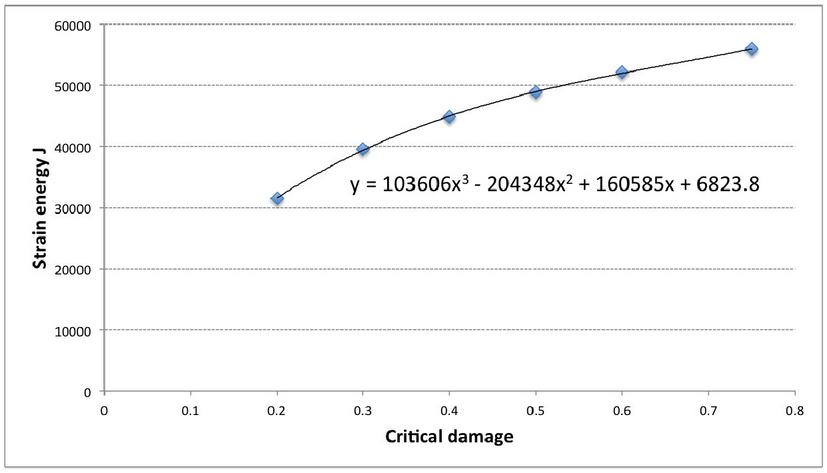
Figure 19 Strain energy as a function of the critical damage. Correlation factor: .
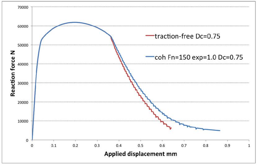
Figure 20 Reaction force-applied displacement curves and respective influence of the cohesive law.
Choosing the parameters of the cohesive law as and , the strain energy obtained is , which is an encouraging result, showing that the proposed methodology is suitable for both plane strain and axisymmetric problems.
4 Discussion
A methodology to describe ductile failure processes has been presented. It incorporates a continuum approach suitable to describe the overall material behaviour with a discontinuous approach which allows a good representation of surface decohesion and tracing of crack paths. In particular, three methodologies have been incorporated, namely, CDM, XFEM and a Cohesive law. A cohesive law may be viewed as the interaction between the two surfaces of a crack and may be used to model material which is not fully degraded. Therefore, an energetically consistent transition from damage to fracture, corresponding to may be approximated by a simulation in which is enhanced by such law. Thus, constructing a function, , relating the strain energy with the critical damage value, it was possible to estimate the strain energy associated with . Subsequently, considering , the parameters of a cohesive were adjusted in order to meet . In this way, a novel interpretation to the cohesive law parameters is outlined. Instead of regarding them as characteristic material properties, they become numerical parameters derived from CDM, in particular associated with critical damage, that is the onset of damage in which a macrocrack evolves in a structure. This feature has the advantage of avoiding specific experimental work to characterize the cohesive law.
The proposed approach exhibit a good performance as illustrated in some numerical examples. However, it assumes that the strain energy associated to follows the same trend of the strain energy for and the target value is determined using approximation techniques, which have a certain error associated. As a result, there are still open questions related to the determination of the cohesive parameters, especially because one single energetic equivalence is used to fit two parameters. In the future, the proposed methodology may be improved by determining the sensitivity of the full model to the cohesive law parameters. We recall that the proposed ductile fracture model features geometrical and material non-linearities, includes a non-local formulation and a discontinuous formulation, and therefore the calculation of the associated sensitivities is not a simple task. Nonetheless, the model is conceptually successful.
Further experimental work is also being prepared. The proposed methodology is independent of the geometry and does not require previous knowledge of the expected crack paths, being suitable for simulating virtually any type of specimen.
Acknowledgments
Authors gratefully acknowledge the funding of Project NORTE-01-0145-FEDER-032419 – msCORE-Multiscale methodology with model order reduction for advanced materials and processes, cofinanced by Programa Operacional Regional do Norte (NORTE2020), through Fundo Europeu de Desenvolvimento Regional (FEDER) and by Fundação para a Ciência e Tecnologia through its component of the state budget.
References
[1] Jacques Besson. Continuum models of ductile fracture: a review. International Journal of Damage Mechanics, 19(1):3–52, 2010.
[2] Arthur L Gurson. Continuum theory of ductile rupture by void nucleation and growth: Part i?yield criteria and flow rules for porous ductile media. 1977.
[3] Viggo Tvergaard and Alan Needleman. Analysis of the cup-cone fracture in a round tensile bar. Acta metallurgica, 32(1):157–169, 1984.
[4] L. M. Kachanov. Time of the rupture process under creep condition. Izv. Akad. Nauk. SSSR Otd. Tekhn. Nauk., 8:26–31, 1958.
[5] Y. N. Rabotnov. On the equation of state of creep. Proceedings of the Institution of Mechanical Engineers, Conference Proceedings, 178(1):2–117–2–122, 1963.
[6] J. Lemaitre. A continuous damage mechanics model for ductile fracture. J. Eng. Mater. Technol., 107(1):83–89, 1985.
[7] J. Lemaitre. Coupled elasto-plasticity and damage constitutive equations. Compt. Meth. App. Mech. Engng., 51(1-3):31–49, 1985.
[8] J. Lemaitre. A course on damage mechanics. Springer, New York, 1996.
[9] J. Chaboche. Continuum damage mechanics - a tool to describe phenomena before crack initiation. Nuclear Engineering and Design, 64(2):233–247, 1981.
[10] J. Lemaitre and J. L. Chaboche. Mechanics of Solid Materials. Cambridge University Press, Cambridge, 1990.
[11] Cihan Tekoğlu, JW Hutchinson, and Thomas Pardoen. On localization and void coalescence as a precursor to ductile fracture. Philosophical Transactions of the Royal Society A: Mathematical, Physical and Engineering Sciences, 373(2038):20140121, 2015.
[12] Nima Allahverdizadeh, Andrea Gilioli, Andrea Manes, and Marco Giglio. An experimental and numerical study for the damage characterization of a ti–6al–4v titanium alloy. International Journal of Mechanical Sciences, 93:32–47, 2015.
[13] M. Vaz and D. R. J. Owen. Aspects of ductile fracture and adaptive mesh refinement in damaged elasto-plastic materials. Int. J. Num. Meth. Engng., 50(1):29–54, 2001.
[14] J. Mediavilla, R.H.J. Peerlings, and M.G.D. Geers. A robust and consistent remeshing-transfer operator for ductile fracture simulations. Comput. Struct., 84(8-9):604–623, 2006.
[15] J Mediavilla, RHJ Peerlings, and MGD Geers. A robust and consistent remeshing-transfer operator for ductile fracture simulations. Computers & structures, 84(8-9):604–623, 2006.
[16] P. Areias, N. Van Goethem, and E. Pires. A damage model for ductile crack initiation and propagation. Comput.Mech., 47:641–656, 2011.
[17] K. Saanouni. On the numerical prediction of the ductile fracture in metal forming. Engng Fract. Mech., 75(11):3545–3559, 2008.
[18] T. Belytschko, W. K. Liu, and B. Moran. Nonlinear Finite Elements for Continua and Structures. Wiley, Chichester, 2000.
[19] P.O. Bouchard, F. Bay, Y. Chastel, and I. Tovena. Crack propagation modelling using an advanced remeshing technique. Comput. Meth. Appl. Mech. Engrg, 189(3):723–742, 2000.
[20] J-H Song, H. Wang, and T. Belytschko. A comparative study on finite element methods for dynamic fracture. Comput Mech, 42(2):239–250, 2008.
[21] S.R. Beissel, G.R. Johnson, and C.H. Popelar. An element-failure algorithm for dynamic crack propagation in general directions. Engng Fract. Mech., 61(3-4):407–425, 1998.
[22] M. Jirásek and T. Zimmermann. Analysis of rotating crack model. J. Engng. Mech., ASCE, 124:842–851, 1998.
[23] Mariana RR Seabra, Primož Šuštarič, Jose MA Cesar de Sa, and Tomaž Rodič. Damage driven crack initiation and propagation in ductile metals using xfem. Computational mechanics, 52(1):161–179, 2013.
[24] N Vajragupta, V Uthaisangsuk, B Schmaling, S Münstermann, A Hartmaier, and W Bleck. A micromechanical damage simulation of dual phase steels using xfem. Computational Materials Science, 54:271–279, 2012.
[25] J. Mazars and G. Pijaudier-Cabot. From damage to fracture mechanics and conversely: A combined approach. Int. J. Solid Struct., 33(20-22):3327–3342, 1996.
[26] G.I. Barenblatt. The mathematical theory of equilibrium cracks in brittle fracture. volume 7 of Advances in Applied Mechanics, pages 55–129. Elsevier, 1962.
[27] D. S. Dugdale. Yielding of steel sheets containing slits. J. Mech. Physics Solids, 8(2):100–104, 1960.
[28] V. Tvergaard and J.W. Hutchinson. Effect of strain-dependent cohesive zone model on predictions of crack growth resistance. Int. J. Solids Struct., 33(20-22):3297–3308, 1996.
[29] N. Chandra, H. Li, C. Shet, and H. Ghonem. Some issues in the application of cohesive zone models for metal-ceramic interfaces. Int. J. Solids Struct., 39(10):2827–2855, 2002.
[30] H. Li and N. Chandra. Analysis of crack growth and crack-tip plasticity in ductile materials using cohesive zone models. Int. J. Plasticity, 19(6):849–882, 2003.
[31] F. Cazes, M. Coret, A. Combescure, and A. Gravouil. A thermodynamic method for the construction of a cohesive law from a non local damage model. Int. J. Solids Struct., 46:1476–1490, 2009.
[32] F. Cazes, A. Simatos, M. Coret, and A. Combescure. A cohesive zone model which is energetically equivalent to a gradient-enhanced coupled damage-plasticity model. Eur. J. Mech. A/Solids, 29:976–989, 2010.
[33] Huan Li, Lei Li, Jiangkun Fan, and Zhufeng Yue. Verification of a cohesive model-based extended finite element method for ductile crack propagation. Fatigue & Fracture of Engineering Materials & Structures, 44(3):762–775, 2021.
[34] P. Areias, J. Cesar de Sa, and C. Conceição António. A gradient model for finite strain elastoplasticity coupled with damage. Finite Elem. Anal. Des., 39(13):1191–1235, 2003.
[35] B. Moran, M. Ortiz, and F. Shih. Formulation of implicit finite element methods for multiplicative finite deformation plasticity. Int. J. Num. Meth. Engng., 29:438–514, 1990.
[36] J.C. Simo, R.L. Taylor, and K.S. Pister. Variational and projection methods for for volume constraint in finite deformation elasto-plasticity. Compt. Meth. App. Mech. Engng., 51:177–208, 1985.
[37] C. Miehe. A constitutive frame of elastoplasticity at large strains based on the notion of a plastic metric. Int. J. Solid Struct., 35(30):3859–3897, 1998.
[38] R. de Borst and E. Giessen. Material Instabilities in Solids. Wiley, New York, 1998.
[39] A. S. Gullerud, X. Gao, R. H. Dodds Jr, and R. Haj-Ali. Simulation of ductile crack growth using computational cells: numerical aspects. Engng. Fract. Mech., 66(1):65–92, 2000.
[40] K.L. Nielsen and J.W. Hutchinson. Cohesive traction-separation laws for tearing of ductile metal plates. Int. J. Impact Engng, 48(0):15–23, 2012.
[41] C.R. Chen, O. Kolednik, J. Heerens, and F.D. Fischer. Three-dimensional modeling of ductile crack growth: Cohesive zone parameters and crack tip triaxiality. Engng. Fract. Mech., 72(13):2072–2094, 2005.
[42] J. Alfaiate, G. Wells, and .J. Sluys. On the use of embedded discontinuity elements with crack path continuity for mode-I and mixed-mode fracture. Engng, Fract. Mech., 69(6):661–686, 2002.
[43] G. C. Sih. Mechanics of Fracture Initiation and Propagation. Kluwer Academic Publishers, Dordrecht, 1991.
[44] N. Moës and T. Belytschko. Extended finite element method for cohesive crack growth. Engng. Fract. Mech., 69(7):813–833, 2002.
Biographies

Mariana R. R. Seabra holds a research and teaching position at the Faculty of Engineering, University of Porto. Her research career has been devoted to numerical methods, in particular the Finite Element Method applied to ductile damage, fracture and fatigue problems.

José M. A. César de Sá is Full Professor at the Faculty of Engineering, University of Porto. His vast career includes several influential publications, mainly but not exclusively, in the field of computational mechanics. He also has been an active participant in relevant scientific associations of the sector such as ECCOMAS or APMTAC.
European Journal of Computational Mechanics, Vol. 30_1, 51–80.
doi: 10.13052/ejcm1779-7179.3012
© 2021 River Publishers