Dynamic Finite Element Analysis of Flexible Double Wishbone Suspension Systems with Different Damping Mechanisms
Alaa A. Abdelrahman*, Ayman E. Nabawy, Soliman S. Alieldin and Ayman M. M. Abdelhaleem
Mechanical Design and Production Dept., Faculty of Engineering, Zagazig University, Zagazig, Egypt
Email: alaaabouahmed@gmail.com
* Corresponding Author
Received 28 June 2019; Accepted 05 February 2020; Publication 09 March 2020
Abstract
Suspension systems in running vehicles keep the occupants comfortable and isolated from road noise, disturbances, and vibrations and consequently prevent the vehicle from damage and wearing. To attain comfortable and vibration isolation conditions, both material flexibility and damping should be considered in the considered suspension model. This paper presents an incremental finite element model to study and analyze the dynamic behavior of double wishbone suspension systems considering both material flexibility and damping effects. The flexibility of the suspension links are modeled with plane frame element based on Timoshenko beam hypothesis (TBH). On the other hand, the flexibility of joints connecting the suspension links together and with the vehicle chassis is modeled with the revolute joint element. To incorporate the damping effect, viscoelastic, viscous and proportional damping are considered. An incremental viscoelastic constitutive relations, suitable for finite element implementation, are developed. The developed finite element equations of motion are solved using the Newmark technique. The developed procedure is verified by comparing the obtained results with that obtained by the developed analytical solution and an excellent agreement is found. The applicability and effectiveness of the developed procedure are demonstrated by conducting parametric studies to show the effects of the road irregularities profiles, the vehicle speed, and the material damping on the transverse deflection and the resultant stresses of suspension system. Results obtained are supportive in the mechanical design, manufacturing processes of such type of structural systems.
Keywords: Viscoelastic, incremental finite element, double wishbone suspension, links flexibility, revolute joint, road irregularities, Timoshenko beam hypothesis (TBH).
1 Introduction
Through the study and analysis of automotive engineering it is most important to study how disturbances from the engine are led into the coupe. Also, one of the most important interest to investigate how disturbances from the roadway propagate through tire, and wheel suspension into the framing and car body. These disturbances may cause undesired noise levels and vibrations, Jonsson [1]. The main objectives of the vehicle suspension systems are listed as follows: Carrying the vehicles and its weight. Maintaining the correct alignment of the wheels. Controlling the travel direction of the vehicles. Finally, minimizing the chock forces effect. Selection of a certain type of suspension system in automotive industry depends on important criteria such as costs, space requirements, kinematic properties, and compliance attributes Rill [2].
Suspension system in its simplest form may be thought of as a set of flexible links connected to each other and to the vehicle chassis through ball joints to allow the wheel to move relative to the body in addition to some elastic element to support loads while allowing that motion, Kamal and Rahman [3]. One of the most important parts in the vehicle suspension systems is the lower control arm which is called as A-type control arm by which the wheel trace is controlled and the load exerting on the wheel by the road is transmitted to other parts of the car, Zhao et al. [4]. In addition, the lower control arm is considered as the most critically loaded member as the load is transferred from the upper arm to the lower control arm causing impact load due to the road irregularities (road bumps), Patil et al. [5]. To avoid failure of the lower control arm, it is essential to focus on the stress analysis study of lower wishbone arm to improve and modify the existing design, these stresses are caused by the dynamic forces which are caused by the dynamic deflections, Dehkordi [6].
Due to the difficulties associated with the boundary conditions and geometrical and/ or material nonlinearities, it is difficult to obtain an analytical closed form solution for such type of problems, the Finite Element Method (FEM) is one of the most effective numerical techniques which can give better conception of the dynamical behavior of this kind of analysis for these systems.
Many considerable research efforts have been dedicated to the design and analysis of the suspension systems.
Based on interval analysis, the kinematic analysis of the mechanisms involved in suspension of vehicles is performed using some exact computational methods, Papegay et al. [7]. Based on gradient determination using exact differentiation, a multi-objective dimensional synthesis technique is used to present the kinematic analysis of double wishbone suspension systems in vehicles, Sancibrian et al. [8]. Using Rodrigue’s parameters and computation of Gröbner basis, the double wishbone and the MacPherson, Reddy et al. [9] developed a complete spatial model for independent suspension systems to investigate the kinematics analysis of these systems. The variable-geometry suspension systems have been synthesized and analyzed in nonlinear manner using the nonlinear polynomial Sum-of-Squares (SOS) programming method Németh and Gáspár [10]. Using variable length arms in an adaptive manner to improve the handling characteristics of a vehicle, camber and toe angles of a double wishbone suspension system are controlled, Kavitha et al. [11]. Based on the point joint coordinate formulation, the dynamic analysis of the double wishbone motor vehicle suspension system is discussed, Attia [12]. Girder and Hos-sack suspension systems, which have the common double wishbone design have been accommodated by modifying the front end geometry based on an existing mathematical model of high-fidelity motorcycle, Ramírez et al. [13].
Many research articles discussed the dynamic behavior of the critically loaded suspension lower control arm. FEM-based suspension arm model and the modal frequencies are established to determine the loads affecting an arm operating in a complete geometric model of a car suspension, Burdzik, and Łazarz [14]. Using the FEM, the fatigue life, von Misses stress, factor of safety and stability of the suspension system are analyzed. Moreover, the weight and size of the suspension system which affect the fuel economy can be reduced, Ijagbemi et al. [15]. By incorporating the frame flexibility and the contacts of the wheel ground, suspension, unsprung mass, and compliance parameters are incorporated to investigate the dynamic behavior using a linear quarter car model, Kanchwala and Chatterjee [16].
To illustrate, the different performance of elastic and composite lower control arms, a comparative study of composite lower wishbone arm and steel lower wishbone arm is performed to investigate the stress-strain analysis using the FEM, Ramesh et al. [17]. The upper control arm has been optimized using Kriging model and the response surface model (RSM) in which the design objective is the control arm weight and the constraint objective is the maximum allowable von Mises stress, Song et al. [18]. Traditional static load optimization techniques and multi-body dynamics are combined using equivalent static load to perform the dynamic optimization of the lower control arm, Zhao et al. [4]. The lower arm of the vehicle suspension system was found to be the most important design variable to achieve noise reduction using sensitivity analysis performed by the FEM determining sensitive design factors, these factors are obtained also from the experimental vehicle tests which compared with those obtained from a robust and efficient sequential approximate optimization method, Kim et al. [19]. Baranowski et al. [20] developed numerical and experimental models for investigating the dynamic response of vehicle tyres under impulse loading conditions. Considering the nonlinear suspension components behaviors, Sayyaadi and Shokouhi [21] developed complete four axle rail vehicle model for investigating vehicle dynamics.
Many research articles present the dynamic behavior of beams based on Timoshenko theory, all Timoshenko beam forced and natural boundary conditions are satisfied using the finite element model, Thomas and Abbas [22]. Analytical expressions for the terms of the coupled bending-torsional dynamic stiffness matrix are derived for a Timoshenko beam with a uniform axial load in an exact sense, Williams [23]. The rail vertical vibration reac-ceptances are calculated by developing a double Timoshenko beam model using both continuously and discretely supported models, Thompson [24]. A cracked Timoshenko beam is presented using a new spectral finite element for the modal and elastic wave propagation analysis, Krawczuk et al. [25]. The dynamic response of the Timoshenko cantilever beam is evaluated with a homogeneous non-prismatic pulse loaded using the Lagrange-d’Alembert principle, Navadeh et al. [26].
According to the best of authors’ knowledge, there is no attempts to develop a finite element model capable of studying and analyzing the dynamic behavior of vehicle suspension systems considering both joint and links flexibilities as well as the internal material damping effects. Thus, the present article aims to fill this gap. Based on Timoshenko beam theory, the plane frame element is adopted to model the flexibility of links while the revolute joint element is used for joint flexibility. The internal viscoelastic as well as the external viscous damping models are considered to investigate the damped response. The developed numerical model is validated and checked by comparing the obtained results with the developed analytical solution and good agreement is obtained.
2 Damping Mechanisms
In spite of large amount of research articles that addressed damping mechanisms in solids and structures, understanding of damping mechanisms is quite basic compared to the other aspects of modelling. This because, in contrast to stiffness and inertia forces, the state variables relevant in determining the damping force are not generally clear, Inman [27]. The most common damping mechanisms in solids and structures are the viscous and the viscoelastic damping mechanisms. In viscously damped systems the damping force is proportional to velocity. The proportionality constant is the damping coefficient. Identifying the material viscous damping coefficient is a major problem. One of the most common idealization to identify the viscous damping coefficient is the Rayleigh or proportional damping model. In this model the viscous damping coefficient is presented by a linear combination of the mass and stiffness of the system, Nakamura [28].
| (1a) |
where [C], [M], [K] are the damping, mass and stiffness matrices; respectively. While α and β are the mass and stiffness matrices multipliers contestants; respectively. These constants are obtained through modal analysis. The damping ratio for the nth mode of such a system is, Cook [29], Chopra [30]:
| (1b) |
Equation (1b) can be expressed for the two modes i and j as
| (1c) |
Assuming constant damping factor, ξ for two modes, i and j, the mass and stiffness multipliers can be expressed as
| (1d) |
Thus proportional damping systems preserve the simplicity of the real normal modes as in undamped systems.
Considering the viscoelastic damping mechanism, according to the superposition principle, the linear viscoelastic constitutive relations can be represented by the convolution integral, Lakes and Lakes [31], Shames [32]
| (2) |
where σij(x,t) and εkl(x, t) are stress and strain tensors; respectively, Rijkl(t − s) is the relaxation modulus, and s is a time variable which defines the time at which the excitation input is applied. The relaxation modulus depends on the viscoelastic mechanical model used to simulate the viscoelastic constitutive response. The viscoelastic behavior is characterized by displacement creep under constant load and stress relaxation under constant prescribed displacement. Modeling the viscoelastic constitutive response using simple Kelvin Voigt or Maxwell mechanical models leads to inaccurate investigation of the real viscoelastic material response. The Maxwell model is good in predicting the stress relaxation response while it can poorly predict the creep response. On the other hand, Kelvin-Voigt is efficient in predicting the creep response while it is not effective for investigating the stress relaxation response. To overcome the drawbacks associated with the simple viscoelastic mechanical models, generalized viscoelastic mechanical models are used. Theses generalized models are generally constructed by using chains of either Maxwell models in parallel combinations or kelvin-Voigt elements in series combination. Throughout this study, the generalized Wiechert model, shown in Figure 1 is used to simulate the linear viscoelastic constitutive response, Abdelrahman and Mahmoud [33]. According to the generalized Wiechert model, the relaxation modulus can be repressed by
| (3) |
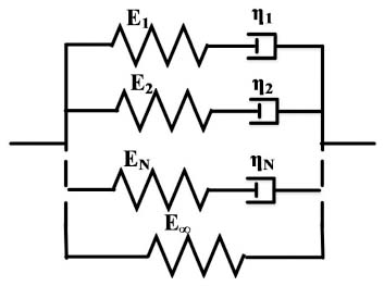
Figure 1 Wiechert viscoelastic material model.
where Eijkl∞ and Eijkln are the fully relaxed and transient modulus of the viscoelastic material, ρn is the material relaxation time and N is the number of Maxwell chains in the generalized Wiechert model. These constants are determined experimentally through either creep or relaxation tests.
3 Mathematical Formulation of Viscoelastically Damped Suspension System
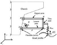
Consider the quarter car model with a planar double wishbone suspension model as shown in Figure 2. According to the proposed planar suspension model, both lower and upper control arms are made of deformable materials (flexible). Moreover, flexible bushings or revolute joints used to connect these arms with vehicle chassis and wheel spindle are modeled by spring elements. On the other hand, suspension strut is modeled by a combination of translational spring and dashpot while tire is simulated by translational spring. To investigate the material damping effect on the dynamic behavior of the system, both viscous and viscoelastic damping models are considered for flexible suspension links, Bahrampour et al. [34]. The tire motion over the road bump, y(t) provides a vertical input which excites the body of the vehicle. Based on the displacement fit conditions and kinematic relations of Timoshenko beam theory (TBT), Reddy [35, 36], Applying the Hamilton’s principle, the dynamic equations of motion of viscoelastically damped systems can be written as, Martin [37] and Hilton [38].
| (4) |
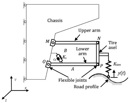
Figure 2 Quarter-car model of a double wishbone suspension.
where t1 and t2 are two arbitrary times, δU and δT are the variations of the strain energy and kinetic energy, respectively which can be expressed as
| (5) |
δWd and δWE are variations of the work done by damping and external forces, respectively.
| (6) |
| (7) |
where, σxx(x, t), τxy(x, t) and , are the elastic and viscous components of normal and shear stress; respectively. Based on the hereditary integral, Findley et al. [39], Vallala et al. [40], both elastic and viscous components of normal and shear stress can be expressed according to the Wiechert viscoelastic mechanical model as, Abdelrahman and Mahmoud [33]
| (8) |
| (9) |
Substituting from Equations (5–9) and evaluating the variations in Equation (4), the dynamic equation of motion for viscoelastically damped Timoshenko beams can be expressed as
| (10) |
| (11) |
| (12) |
4 Numerical Evaluation of the Viscoelastic Constitutive Equations
To develop a computational finite element model capable of investigating the dynamic response of viscoelastically damped suspension system, the hereditary integral should be expressed in an incremental recursive form suitable for the finite element implementation, Yi and Hilton [41]. According to Wiechert viscoelastic model, the normal and shear stress components for linear isotropic materials can be expressed as
| (13) |
| (14) |
Equations (13, 14) can be written as
| (15) |
| (16) |
Applying the trapezoidal rule, Equations (15, 16) can be numerically evaluated and the viscoelastic constitutive relations an incrementally expressed as
| (17) |
where and are the normal and shear stress components at the current time instant, t which can be expressed as
| (18) |
| (19) |
while and are the normal and shear stress history components which can be expressed as
| (20) |
| (21) |
with hnσ(x, t) and hnτ(x, t) are given by
| (22) |
| (23) |
More details for the numerical evaluation of the convolution integrals in the viscoelastic constitutive form is presented in Appendix A.
5 Finite Element Model
To derive the incremental finite element equations of motion, the double wishbone suspension links are divided into finite elements. Both two nodded and three nodded isoparametric Timoshenko beam elements are considered, Capsoni et al. [42]. On the other hand, the revolute joint element developed in ANSYS Kohnke [43] is adopted to model the joint flexibility of the suspension system. Based on TBT, the dynamic finite element equations of motion is established by applying the virtual work principle, taking into account d’Alembert’s principle and considering viscoelastic damping forces as
| (24) |
where Px, Pz, and m refer to the distributed normal, shear and bending moment while ρ is the mass density. Equation (24) can be rewritten as
| (25) |
The displacement, strain displacement relation and the constitutive relations for linear viscoelastic materials can be expressed in matrix form as, Oñate [44]
| (26a) |
| (26b) |
| (26c) |
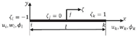
where εx, κx, γxy are the normal strain, the curvature and the shear strain components; respectively, Ne is the element shape function matrix and Be is the strain displacement relation matrix for the three noded Timoshenko beam (TB) element, shown in Figure 3.
| (27a) |
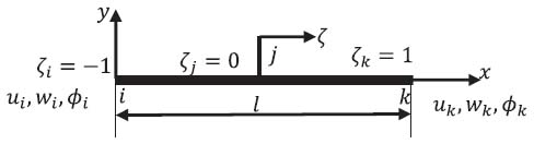
Figure 3 Three noded isoparametric TB element.
| (27b) |
where A, ks, ν and I are the beam element cross sectional area, the TB shear correction factor, Poisson’s ratio, and the beam second moment of area; respectively. Substituting Equations (26), (27) into Equation (25), the dynamic finite element equation of motion for viscoelastic system can be written in global coordinates as
| (28) |
By the same way, the dynamic finite element equation of motion for viscously damped TBT can be written in global coordinates as
| (29) |
where , , , R and are the element mass, stiffness, and viscous damping, transformation matrices and the force vector due to viscoelastic material history; respectively.
| (30) |
Considering the revolute joint element, COMBIN7 as expressed in ANSYS, the dynamic equation of motion can be expressed in matrix form as
| (31) |
where kx and ky are dependent on the geometry and material characteristics of the revolute joint while kt is dependent on the generated frictional torque during the relative motion between the two mating surfaces. While cv is the viscous damping coefficient of the revolute joint which depends on the type and the extent of the contact area between the two mating surfaces in the joint. Finally, m and I are the total mass and mass moment of inertia of the revolute joint; respectively.
6 Validation of the Developed Model
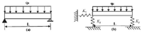
Within this section the capability of the developed model to analyze the dynamic behavior of elastic and/or viscoelastic structures under different excitation patterns is verified. Consider a simply supported beam under uniformly distributed load with intensity of q0, as shown in Figure 4. To check the validity of the developed model for joint flexibility, both hinged and roller supports can be represented by flexible translational springs, as shown in Figure 4(b). Froio and Rizzi [45] and Da Costa Azevêdo [46]. Higher values of these spring stiffness leads to fully rigid support consequently the same response should be detected for both rigid and flexible supports with higher stiffness values. Moreover, both EBBT and TBT are considered during the verification procedure. The parameters used for numerical analysis are listed as follows: The load intensity q0 = 100 N/m. The beam has a length of L = 4 m, width b = 0.2 m, and height, h = 0.4 m. The modulus of elasticity of elastic material, mass density, shear correction factor, and Poisson’s ratio are taken to be E = 9.8 × 10⁷ Pa, ρ = 500 kg/m3, ks = 5/6, and v = 0.3, respectively. The viscoelastic material parameters for a single repeated model are, the fully relaxed modulus, E8 = 1.96 × 10⁷ Pa, the transient modulus E1 = 7.84 × 10⁷ Pa, and the material relaxation time ρv = 2.24 s while the instantaneous creep compliance D0 = 1.2041 × 10⁻⁸ Pa−1, the transient creep compliance D1 = 4.0816 × 10⁻⁸ Pa−1, and the viscoelastic retardation time τ = 11.2 s. Beams are discretized into beam elements. The elastodynamic and viscoelastodynamic transient responses are detected by applying the Newmark’s numerical integration technique.
The analytical quasi-static viscoelastic solution based on the elastic viscoelastic correspondence principle can be expressed for both TBT and EBBT as, Vallala et al. [40]
| (32) |
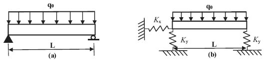
Figure 4 Geometry of the simply-supported and elastically supported beams.
where D(t) is the viscoelastic creep compliance function which can be defined as
| (33) |
with D0 is the equivalent elastic compliance of the viscoelastic material and Dn is the transient component of the viscoelastic material. On the other hand, the semi analytical elastodynamic solution for both TBT and EBBT can be written as, Abdelrahman et al. [47]
| (34) |
where
| (35) |
Moreover the semi analytical viscoelastodynamic deflection can be obtained using the mixed Galerkin’s Laplace techniques for EBBT as, Abdelrahman et al. [47]; Martin [37]
| (36) |
where
| (37) |
where
| (38) |
| (39) |
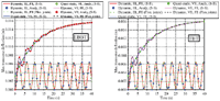
The maximum transverse deflection is investigated for both numerical and analytical analyses over a time interval [0, 40] s for both EBBT and TBT. The dependency of the transverse deflection on time for both viscoelastic and elastic materials behavior for quasistatic and dynamic analyses for both simply supported rigid support (S-S) and restrained supported beam with large values of the spring stiffness (flex. support) are illustrated in Figure 5. It is noticed that an excellent agreement is obtained between both numerical and analytical solutions. Moreover, at very high values of the support spring stiffness, both S-S rigid support and flexible support analyses result in the same response for both elastic and viscoelastic behavior.
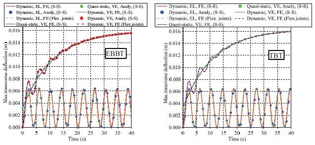
Figure 5 Variation of the maximum deflection with time for different materials behavior for both EBBT and TBT.
7 Computational Results
The applicability of the developed model to study and analyze the dynamic behavior of the double wishbone suspension system under trapezoidal road bump profile and at different values of travelling velocity is demonstrated in this section. Moreover, to study the material damping effect on the transient response, both undamped, proportional, and viscoelastic damped responses are investigated. The maximum transverse deflection and the resultant stresses at the critically loaded point on the lower control arm of the double wishbone suspension system are investigated. Exploiting the symmetry of the vehicle, only a quarter car model is simulated. The wheel center is subjected to the different excitations based on the road bump profile. The comprehensive quarter car model incorporating double wishbone linkage shown in Figure 2. is presented for the discussion including the tire and strut as flexible translational springs while the chassis and the tire axle are considered rigid compared to the lower and upper control arms. The model geometrical parameters and material characteristics used to obtain the computational results are summarized in Table 1.
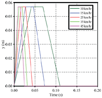
The road disturbance as the system excitation results in vertical vibrations in the whole system. Trapezoidal road disturbance profile is considered to investigate the effect of road irregularity (bump) profile on the dynamic response of the suspension systems. Variation of the trapezoidal road bump profile with time at different vehicle velocities is illustrated in Figure 6, Hassaan [46].
7.1 Effect of Vehicle Velocity on the Transient Response of the Lower Control Arm
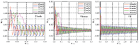
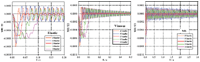
The vehicle velocity during passing over the road bump greatly affects the transient response of the vehicle suspension system. The transient response of the lower control arm is investigated for the different vehicle velocities; 10, 15, 25, 35, and 45 km/hr for different material behaviors. Variations of the maximum normalized transverse deflection (W/L) at the critically loaded point on the lower control arm with the normalized time (T/τ), (τ = ρv) at different travelling velocities for elastic, proportional viscously damped and viscoelastic damped behaviors are depicted in Figure 7. It is noticed that, the time needed to reach the peak value of the transient response and to drop to the minimum amplitude greatly affected by the vehicle velocity. It is also noticed that for the maximum transverse deflection, although the peak amplitude of vibration is detected at the maximum value of the vehicle velocity (v = 45 km/hr) the smallest amplitude is obtained at a vehicle velocity of 25 km/kr. Thus the smallest vibration amplitude is not obtained at the smallest value of the vehicle velocity. On contrary to the transient elastic response which proceeds with a constant amplitude for all vehicle velocities, the transient proportional viscously damped response is decaying rapidly due to the constant damping ratio while the viscoelastic transient response is continuously decaying gradually with time due to the algorithmic viscoelastic damping. The decaying rate and consequently the time required to reach the steady state oscillations for the viscoelastic transient response depends on the viscoelastic relaxation time.
Table 1 The physical properties of the suspension elastic model
| Parameter | Value |
|---|---|
| E (GPa), (Elastic suspension links) | 210 |
| E∞ (GPa), (VE suspension links) | 42 |
| E1 (GPa), (VE suspension links) | 168 |
| ρv (s), Relaxation time (VE suspension links) | 1.0 |
| E (GPa), (chassis and tire axle) | 1050 |
| ρ, kg/m3, (chassis and suspension links) | 7830 |
| Ks (N/mm), (Strut stiffness) | 340 |
| Ktire (N/mm), (Tire stiffness) | 235 |
| Kx (N/mm), (flex. Joint) | 17.544 × 10⁷ |
| Ky (N/mm), (flex. Joint) | 17.544 × 10⁷ |
| Kt (N/mm), (flex. Joint) | 19.737 × 10⁴ |
| A m2 | 6 × 10⁻⁴ |
| L (Lower and upper arm length) | 0.4 m |
| I m4 | 12 × 10−8 |
| Cv (N.s/m) | 4 × 10⁴ |
| ξ(—) | 75 × 10−4 |
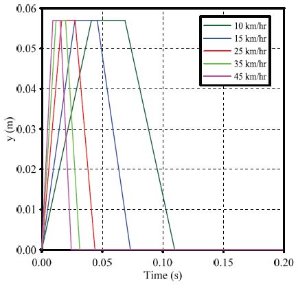
Figure 6 Variation of road profile with time at different vehicle velocities.
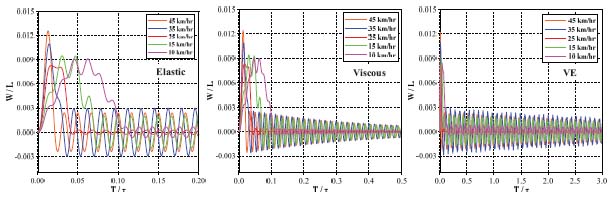
Figure 7 Variation of the maximum transverse deflection with time for different material behaviors at different vehicle velocities.
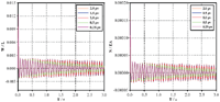
The dependency of the maximum normalized normal force (N/τ) on the normalized time (T/τ) for different material behaviors is illustrated in Figure 8. It is noticed that, as detected for the maximum normalized transverse deflection, the preferable transient response for trapezoidal road bump profile is detected at vehicle velocity of 25 km/hr. It is noticed that, higher and constant steady state oscillation amplitude is detected for the transient elastic response compared with both proportional viscously damped and viscoelastically damped response. Also, the proportional viscously damped response needs short time interval to decay to smaller oscillation amplitude due to the constant damping ratio. On the other hand, depending on the viscoelastic relaxation time, long time interval is needed for the viscoelastic transient response to reach the corresponding smaller oscillation amplitude.
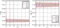
The maximum normalized shear force, (V/EA) versus the normalized time (T/τ) for elastic, proportional viscously damped, and viscoelastically damped responses is depicted in Figure 9. It is noticed that, smaller values of the instantaneous and steady state oscillation amplitudes of the maximum normalized shear force are detected compared with the obtained maximum normal force for all material behaviors. It is also noticed that preferable response is detected at vehicle velocity of 25 km/hr.
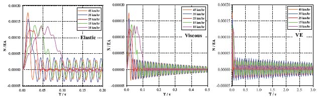
Figure 8 Variation of the maximum normal force with time for different material behaviors at different vehicle velocities.
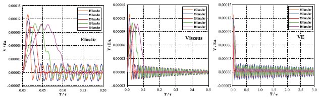
Figure 9 Variation of the maximum shear force with time for different material behaviors at different vehicle velocities.
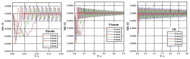
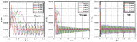
Figure 10 Variation of the maximum bending moment with time for different material behaviors at different vehicle velocities.
Variation of the maximum normalized bending moment with the normalized time for different material responses is depicted in Figure 10. It is noticed that, due to material damping, both proportional viscously and viscoelastically damped response possesses stress relaxation leading to decayed oscillation amplitudes compared with the corresponding transient elastic response. The decaying rate depends on the both the viscous damping ratio and the viscoelastic material relaxation time.
7.2 Effect of the Viscoelastic Relaxation Time on the Transient Response of the Lower Control Arm
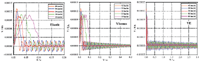
The relaxation time of the viscoelastic control arm greatly affects the decaying rate of the transient response of the double wishbone suspension system. The transient response of the lower control arm is investigated for different values of the relaxation time (ρv); 0.25 ρv, 0.5 ρv, ρv, 1.5 ρv, and 2 ρv. The dependency of the maximum normalized transverse deflection, the normal force, the shear force, and the bending moment on the normalized time at the critically loaded point of the viscoelastic lower control arm at different values of the relaxation time is illustrated in Figures 11 and 12, respectively. It is noticeable that the same instantaneous response is detected for all values of the relaxation time. On the other hand the decaying rate of the transient response oscillation amplitudes are increased with decreasing the viscoelastic relaxation time and consequently, the time required to reach the steady state amplitude is decreased with decreasing the relaxation time.
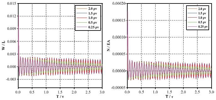
Figure 11 Variation of the maximum transverse deflection and the maximum normal force for different values of the relaxation time.
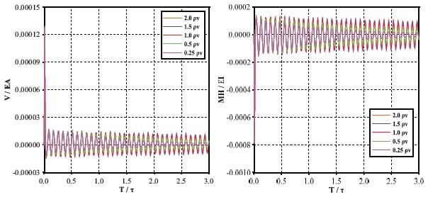
Figure 12 Variation of the shear force and the maximum bending moment at for different values of the relaxation time.
8 Conclusion
An incremental finite element model capable of investigating the dynamic behavior of double wishbone vehicle suspension system is proposed considering both links and joints flexibilities as well as the internal vis-coelastic material damping effects. Besides the internal viscoelastic damping proportional damping mechanisms is considered to show the effect of different damping techniques on the dynamic behavior of the double wishbone suspension systems. The TBT is adopted to model the control arm flexibility. On the other hand, the revolute joint element developed in ANSYS is adopted to model the flexibility of bushings. An incremental viscoelastic constitutive relation suitable for finite element procedure is developed. The proposed procedure is verified by comparing the obtained results with the available analytical forms and an excellent agreement is detected. Parametric studies are conducted to study the effects of the travelling velocity and the viscoelastic relaxation time on the transient response of the suspension lower control arm. The obtained results shows that
- The vehicle travelling velocity over the road bump affects both the instantaneous and the steady state response of the suspension system. Smaller oscillation amplitude of the transient response does not correspond to the smallest vehicle travelling velocity over the road bump. The most preferable travelling velocity over the road bump depends on the bump profile and the material characteristics.
- The transient elastic response possesses higher values of the steady state amplitudes compared with the corresponding proportional viscously and viscoelastically damped responses due to the absence of damping.
- The proportional viscously damped response exhibits rapidly decaying oscillation amplitudes for both the transverse deflection and the resultant stress due to the constant damping factor which is determined based on the real normal modal analysis of undamped system. Unfortunately, most real physical structures possess complex modes instead of real normal modes. Thus proportional viscous damping model does not simulate the actual behavior of the real physical materials.
- Depending on the viscoelastic relaxation time, the viscoelastically damped response produces slowly decaying oscillation amplitude compared with the proportional viscously damping mechanism. Thus longer time interval is needed to reach a steady state oscillation amplitudes.
- The viscoelastic relaxation time has a great effect on the transient response of the vehicle suspension lower control arm. Increasing the viscoelastic relaxation time results in decreasing the value of the steady state amplitude and the time required to reach it.
- The viscoelastic damping model is more suitable for modelling the damping mechanism in solids and structures. This is because, all the viscoelastic material damping parameters are determined experimentally through either creep or relaxation tests not on modal analysis bases. Thus simulating the actual behavior of real life solids and structures.
Appendix A
A Numerical Approximation for the Convolution Integral
| (A1) |
The first term in Equation (A1) can be simplified using the trapezoidal rule as
| (A2) |
Evaluating the integral in Equation (A2) yields;
| (A3) |
Simplifying Equation (A3) yields;
| (A4) |
Evaluating the integral and simplifying Equation (A4) yields
| (A5) |
The second integral in Equation (A1) can be simplified as
| (A6) |
Consequently, the viscoelastic constitutive relation can be expressed as
| (A7) |
References
[1] M. Jonsson, Simulation of dynamical behaviour of a front wheel suspension. Vehicle Syst Dyn, 20(5), (1991) 269–281.
[2] G. Rill, Road vehicle dynamics: fundamentals and modeling. Crc Press, 2011.
[3] M. Kamal and M. M. Rahman, Study on dynamic behaviour of wishbone suspension system. In IOP Conference Series: Materials Science and Engineering, 36(1), (2012), 012019, IOP Publishing.
[4] L. Zhao, S. Zheng, J. Feng and Q. Hong, Dynamic Structure Optimization Design of Lower Control Arm Based on ESL. Research J App Sci, Eng Tech, 4(22), (2012) 4871–4878.
[5] A. M. Patil, A. S. Todkar, R. S. Mithari and V. V. Patil, Experimental and Finite Element Analysis of Left Side Lower Wishbone Arm of Independent Suspension System. IOSR J Mech Civil Eng, 2013 (2013).
[6] H. D. Banitalebi, Vibration and force analysis of lower arm of suspension system, Doctoral dissertation, Université du Québec á Chicoutimi, 2014.
[7] Y. A. Papegay, J. P. Merlet and D. Daney, Exact kinematics analysis of Cars suspension mechanisms using symbolic computation and interval analysis. Mechanism and Machine Theory, 40(2005) 395–413.
[8] R. Sancibrian, P. Garcia, F. Viadero, A. Fernandez and A. De-Juan, Kinematic design of double-wishbone suspension systems using a multi-objective optimization approach. Vehicle System Dynamics: International Journal of Vehicle Mechanics and Mobility, 48(7), (2010) 793–813.
[9] K. V. Reddy, M. Kodati, K. Chatra and S. Bandyopadhyay, A comprehensive kinematic analysis of the double wishbone and MacPherson strut suspension systems. Mechanism and Machine Theory, 105 (2016) 441–470.
[10] B. Németh and P. Gáspár, Nonlinear analysis and control of a variable-geometry suspension system. Control Engineering Practice, 61 (2017) 279–291.
[11] C. Kavitha, S. A. Shankar, K. Karthika, B. Ashok and S. D. Ashok, Active camber and toe control strategy for the double wishbone suspension system. Journal of King Saud University-Engineering Sciences, (2018).
[12] A. H. Attia, Dynamic modelling of the double wishbone motor-vehicle suspension system. Eur J Mech A/Solids, 21 (2002) 167–174.
[13] C. M. Ramírez, M. Tomás-Rodríguez and S. A. Evangelou. Dynamic analysis of double wishbone front suspension systems on sport motorcycles. Nonlinear Dynamics, 91(4) (2018), 2347–2368.
[14] R. Burdzik and B. Łazarz, Analysis of properties of automotive vehicle suspension arm depending on different materials used in the MSC. Adams environment. Archives of Materials Science and Engineering, 58(2), (2012) 171–176.
[15] C. O. Ijagbemi, B. I. Oladapo, H. M. Campbell and C. O. Ijagbemi, Design and simulation of fatigue analysis for a vehicle suspension system (VSS) and its effect on global warming. Procedia Engineering, 159, (2016) 124–132.
[16] H. Kanchwala and A. Chatterjee. A generalized quarter car modelling approach with frame flexibility and other nonlocal effects. Sâdhanâ, 42(7), (2017), 1175–1192.
[17] U. A. Ramesh, D. Siddhartha, R. A. Sethu, N. Ramanan and V. Karthi, Modeling and analysis of lower wishbone for independent suspension system for commercial vehicles. Journal of Chemical and Pharmaceutical Sciences, 2 (2017), 166–168.
[18] X. G. Song, J. H. Jung, H. J. Son, J. H. Park, K. H. Lee and Y. C. Park, (2010). Metamodel-based optimization of a control arm considering strength and durability performance. Computers & Mathematics with Applications, 60(4), 976–980.
[19] Y. D. Kim, J. E. Jeong, J. S. Park, I. H. Yang, T. S. Park, P. B. Muhamad and J. E. Oh, Optimization of the lower arm of a vehicle suspension system for road noise reduction by sensitivity analysis. Mechanism and Machine Theory, 69(2013) 278–302.
[20] P. Baranowski, J. Malachowski and L. Mazurkiewicz, Numerical and experimental testing of vehicle tyre under impulse loading conditions. Int J Mech Sci, 106 (2016) 346–356.
[21] H. Sayyaadi and N. Shokouhi, A new model in rail–vehicles dynamics considering nonlinear suspension components behavior. International Journal of Mechanical Sciences, 51(3), (2009). 222–232.
[22] J. Thomas and B. A. H. Abbas. Finite element model for dynamic analysis of Timoshenko beam. Journal of Sound and Vibration 41, no. 3 (1975): 291–299.
[23] J. R. Banerjee and F. W. Williams. Coupled bending-torsional dynamic stiffness matrix of an axially loaded Timoshenko beam element. International Journal of Solids and Structures 31, no. 6 (1994): 749–762.
[24] T. X. Wu and D. J. Thompson. A double Timoshenko beam model for vertical vibration analysis of railway track at high frequencies. Journal of Sound and Vibration 224, no. 2 (1999): 329–348.
[25] M. Krawczuk, M. Palacz and W. Ostachowicz. The dynamic analysis of a cracked Timoshenko beam by the spectral element method. Journal of Sound and Vibration 264, no. 5 (2003): 1139–1153.
[26] N. Navadeh, R. W. Hewson and A. S. Fallah. Dynamics of transversally vibrating non-prismatic Timoshenko cantilever beams. Engineering Structures 166 (2018): 511–525.
[27] D. J. Inman, Engineering vibration. Pearson: Pearson Education; (4th ed.), (2014).
[28] N. Nakamura, Time history response analysis using extended Rayleigh damping model. Procedia Engineering, 199, 1472–1477, (2017).
[29] R. D. Cook, D. S. Malkus and M. E. Plesha, “Stress Stiffening and Buckling”, in Concepts and Applications of Finite Element Analysis, (John Wiley & Sons, New York), pp. 429–448 (1989).
[30] A. K. Chopra, “Damping in structures”, in Dynamics of Structures, (Prentice-Hall Inc., Upper Saddle River, New Jersey), pp. 409–429, (1995).
[31] R. Lakes and R. S. Lakes, Viscoelastic Materials. Cambridge university press, (2009).
[32] I. H. Shames, Elastic and Inelastic Stress Analysis. CRC Press, (1997).
[33] A. A. Abdel Rahman and F. F. Mahmoud, Analysis of nanocontact problems of layered viscoelastic solids with surface energy effects under different loading patterns. Acta Mech. 227(2), (2016) 527–548.
[34] M. Bahrampour, S. J. Hamzeh and S. Shojaee, New Insight into Vis-coelastic Finite Element Modeling of Time-Dependent Material Creep Problems Using Spherical Hankel Element Framework. International Journal of Applied Mechanics, 1850085, 2018.
[35] J. N. Reddy, Theory and analysis of elastic plates and shells. 2nd ed. Boca Raton, FL: CRC Press; 2007.
[36] J. N. Reddy, Microstructure-dependent couple stress theories of functionally graded beams. J Mech Phys Solids, 59(2018) 2382–99.
[37] O. Martin, A modified variational iteration method for the analysis of viscoelastic beams. Applied Mathematical Modelling, 40(17–18), (2016) 7988–7995.
[38] H. H. Hilton, Viscoelastic Timoshenko beam theory, Mech of Time-Depend Mat, 13(1), (2009) 1–10.
[39] W. N. Findley and F. A. Davis, Creep and relaxation of nonlinear viscoelastic materials. Courier Corporation, 2013.
[40] V. P. Vallala, G. S. Payette and J. N. Reddy, A spectral/hp nonlinear finite element analysis of higher-order beam theory with viscoelasticity. Int J Appl Mech, 4(1), 1250010, (2012).
[41] S. Yi and H. H. Hilton, Dynamic finite element analysis of viscoelastic composite plates in the time domain. International Journal for Numerical Methods in Engineering, 37(23), 4081–4096, (1994).
[42] A. Capsoni, G. M. Viganò and K. Bani-Hani, On damping effects in Timoshenko beams. Int J mech sci, 73 (2013) 27–39.
[43] P. Kohnke, ANSYS Theory Reference, Release 5.5 ANSYS. Inc., Canonsburg, (1997).
[44] E. Oñate, Structural analysis with the finite element method. Linear statics: volume 2: beams, plates and shells. Springer Science & Business Media (2013).
[45] D. Froio and E. Rizzi, Analytical solution for the elastic bending of beams lying on a variable Winkler support. Acta Mechanica, 227(4), (2016) 1157–1179.
[46] A. S. Da Costa Azevêdo, A. C. A. Vasconcelos and S. dos Santos Hoefel, Dynamic analysis of elastically supported Timoshenko beam. Revista Interdisciplinar de Pesquisa em Engenharia-RIPE, 2(34), (2016) 71–85.
[47] A. A. Abdelrahman, M. A. Eltaher, A. M. Kabeel, A. M. Abdraboh and A. A. Hendy, Free and forced analysis of perforated beams. Steel and Composite Structures, 31(5), (2019), 489–502.
[48] G. A. Hassaan, Car Dynamics Using Quarter Model and Passive Suspension, Part IV: Destructive Miniature Humps (Bumps). Global Journal of Advanced Research, 2(2), (2015) 451–463.
Biographies

Alaa A. Abdelrahman Associate Professor in mechanical design and production Engineering Department at Zagazig University, Faculty of Engineering since July 2019. His research focuses on Computational Mechanics of Deformable solids and structures.

Ayman E. Nabawy received his M.Sc. degree in Mechanical Engineering at the Zagazig University in 2019. He is currently a PhD student at the department of Mechanical Design and Production Engineering, faculty of Engineering at Zagazig University. His research focuses on Modeling and analysis of the dynamic behavior of deformed solids and structures.

Soliman S. Alieldin, Professor in mechanical design and production Engineering Department at Zagazig University, Faculty of Engineering. His research focuses on Theoretical, Experimental, and Computational Mechanics of materials and structures.

Ayman M. M. Abdelhaleem, Associate Professor in mechanical design and production Engineering Department at Zagazig University, Faculty of Engineering. His research focuses on Analysis, Design, control of motor vehicle systems.
European Journal of Computational Mechanics, Vol. 28-6, 573–604.
doi: 10.13052/ejcm2642-2085.2862
© 2020 River Publishers