Study on the Mechanical Properties of Hydraulic Tunnels With High Ground Temperature and the Temporal and Spatial Evolution of Plastic Zone
Haijuan Wang, Haibo Jiang* and Fengchun Yang
College of Water and Architectural Engineering, Shihezi University, Shihezi 832000, China
E-mail: klaud_123@163.com
Corresponding Author
Received 21 July 2021; Accepted 09 August 2021; Publication 07 September 2021
Abstract
In order to explore the temporal and spatial evolution of the mechanical characteristics of hydraulic tunnels with high ground temperature during construction, a numerical simulation study was performed on the construction process of the tunnel using finite element calculation software, and the results were compared with the field monitoring results. The results showed that the displacements of the top arch and waist arch of the tunnel increased with time, and the top arch of the tunnel entrance was greatly affected by the excavation. The plastic zone was larger in the top arch and the bottom arch of surrounding rock, and smaller in the waist arch. The plastic strain of the top arch and bottom arch of surrounding rock was smaller, while the plastic strain of the waist arch was larger. The parallel excavation and lining construction have less impact on the surrounding rock.
Keywords: High ground temperature, hydraulic tunnel, temporal and spatial evolution, force characteristics.
1 Introduction
With the country’s strong support for industrial construction, many tunnel projects have emerged. At the same time, the construction of tunnel projects has become increasingly difficult. During the construction of tunnel projects, the characteristics of rock mass and its evolution mechanism have always been a hot issue concerned by scholars. Gong Jianwu et al. [1] established a 3D finite element model based on a three-lane super-close road tunnel, studied the temporal and spatial mechanical characteristics of the tunnel construction process. Wang Yunfei [2] measured the mechanical parameters through the unconfined compression test of the coal, and used the particle flow software and the compiled Fish program to obtain the micromechanical parameters of the coal. Based on Yunnan Dianzhong Water Diversion Project, Si Jianqiang [3] analyzed the temporal and spatial effects of creep deformation of soft rock, and studied the reserved deformation of the lining of the tunnel excavation, the reasonable timing of the support system, and the force of the lining. Fan Chengyu [4] used FLAC3D to establish a three-dimensional model of the opening to analyze the stress and displacement changes of the surrounding rock under the four optimization schemes, and finally determined the optimal scheme. Yang Yongwei [5] established a three-dimensional numerical model of a new tunnel underneath an existing tunnel, and studied the deformation laws and mechanical change characteristics of the existing tunnel structure when the new tunnel with different thicknesses of surrounding rock approached and moved away from the existing tunnel. Yang Chunshan [6] took the shield tunnel of Guangzhou Xijiang Water Diversion Project as an engineering example, analyzed the bearing and interaction mechanism of multi-layer composite lining, established a fine calculation model of composite lining shield construction. However, compared with the construction problems of general tunnel project, as the depth of tunnel construction continues to increase, the tunnel construction at high ground temperature is obviously more challenging [7–9]. With the progress of construction, the excavation depth continuously increases. Due to the temperature difference, there is a continuous heat transfer process between the surrounding rock and the air affected. This transient heat transfer process makes the construction environment of high ground temperature hydraulic tunnels more complicated, and it has also been thoroughly studied by scholars in China and other countries. Duolei Kuai [10] studied the distribution law of three spontaneous combustion zones in goaf of fully mechanized mining face under high ground temperature, employed software Fluent to perform numerical simulations on the O2 concentration distribution in the goaf. Gao Ping [11] studied the thermal physical parameters of the rock and the coupled model of multi-field thermal effects to determine the temporal and spatial evolution of the temperature field, seepage field and stress field. Meng Yao [12] studied the characteristics and variation law of temperature field in hydraulic tunnel under different environmental conditions. Although the wind velocity had a significant effect on the temperature distribution of the surrounding rock, it did not change its symmetrical distribution characteristics. Zhang Yuan et al. [13, 14] reported that the temperature gradient and heat flux density at the wall of the underground cavern were the largest. As the distance from the wall increased, the temperature gradient and heat flux density gradually decreased. In addition, as the ventilation time extended, the range of temperature disturbance in the surrounding rock of the cavern gradually expanded, and it was a power function of the dimensionless time of unsteady heat conduction. Wang Yijiang [15] found that the wall temperature of underground caverns had a great relationship with the convective heat transfer coefficient. In order to study the whole process of progressive failure of marble at different temperatures, Guo Qinglu et al. [16] performed uniaxial compression tests on marble at 25C, 200C, 400C and 600C, and studied the acoustic emission characteristics, failure modes, range of initiation stress and damage stress, damage evolution law and stress-strain model of rock masses. In the construction of tunnel and other underground projects, the rock mass stress can be measured accurately by field monitoring, but due to the high cost and difficult drilling conditions, the field testing method can not be used in large numbers, and the measured stress samples are rare and it is difficult to express the variation law of rock mass mechanical properties [17–20]. Therefore, it is of great theoretical value to invert the stress field of rock mass in order to obtain the macro-distributed mechanical properties of rock mass [21–23].
Based on the above results, the evolution mechanism of the mechanical characteristics of tunnel engineering and the temporal and spatial evolution of the temperature field of high ground temperature tunnels has been studied maturely. However, the evolution of the mechanical characteristics during the excavation of high ground temperature tunnels has rarely been studied. In the high ground temperature tunnel project, the safe construction of the tunnel is an important prerequisite to ensure the stable operation of the tunnel. In order to explore the spatial and temporal evolution law of mechanical characteristics of hydraulic tunnel with high geothermal temperature during construction, and reveal the change law of displacement, stress and development of plastic zone of surrounding rock of tunnel, it is necessary to conduct in-depth research on the mechanical characteristics of the high ground temperature tunnel during the construction. In this paper, a hydraulic tunnel in Xinjiang was used as the research background, and the whole process of excavation of the high-temperature tunnel section of the project was numerically simulated. The temporal and spatial distribution of the mechanical characteristics of the surrounding rock lining of the high-temperature diversion tunnel was obtained. The results provide reference for related research on hydraulic tunnels with high ground temperature.
Temporal and Spatial Distribution of Mechanical Characteristics of Surrounding Rock With High Ground Temperature
1.1 Parameter Selection in Project Overview Model
1.1.1 Project overview
A water conservancy project in Xinjiang is a large (2) second-class project with comprehensive utilization benefits such as irrigation, power generation, flood control, and improvement of the ecological environment. This project is the only controlled reservoir on the Gaizi River with multi-year regulation performance. The proposed project is mainly composed of a barrage, diversion and spillway sand tunnels, open spillways, power diversion tunnels, power plants, tail water, etc. The power diversion tunnel is located on the left bank of the Gaizi River, and the inlet is about 240 m upstream of the VIII dam line. During the construction of the tunnel, serious rock bursts and high ground temperature occurred. According to the results of on-site monitoring, the maximum temperature in the borehole of the project reached more than 100C, which indicated that this was a typical diversion tunnel with high depth and high ground temperature.
Table 1 Mechanical and thermal parameters of surrounding rock
| Temperature | Elastic Modulus/ GPa | Thermal Conductivity/ W/(mC) | Linear Expansion Coefficient/ C*10 | Specific Heat Capacity/ J/KgC | Poisson’s Ratio | Internal Friction Angle/ | Cohesion/ MPa |
| 20 | 7.1 | 10 | 5.0 | 1060 | 0.35 | 42 | 1.1 |
| 35 | 7.0 | 9.4 | 5.6 | 1105 | 0.35 | 42 | 1.1 |
| 50 | 6.9 | 8.9 | 6.2 | 1150 | 0.35 | 42 | 1.1 |
| 65 | 6.8 | 8.4 | 6.9 | 1195 | 0.35 | 42 | 1.1 |
| 80 | 6.7 | 8.0 | 7.6 | 1240 | 0.35 | 42 | 1.1 |
| 95 | 6.5 | 7.6 | 8.3 | 1285 | 0.25 | 42 | 1.1 |
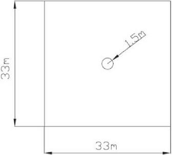
Figure 1 Model plan dimensions.
Model Parameter Selection
According to the geological characteristics of this project, the surrounding rock grade of the project was Class III, the tunnel excavation and standing time was 130 days, the construction excavation length was 50 m, the analysis step was 3 m, the buried depth of surrounding rock was 370 m, and the diameter of the tunnel was 3.0 m. Thus, the calculation range of the surrounding rock numerical simulation model was 33 m * 33 m. The size of the surrounding rock model is shown in Figure 1. The high ground temperature diversion tunnel model adopted the transient temperature-displacement coupling model, and used the direct coupling method to simulate the construction process of the high ground temperature rock mass. The temperature boundary conditions were determined based on the field monitoring results. Since the average temperature of the original rock was 80C, the temperature boundary condition of the surrounding rock was set to 80C. After excavation, the surrounding rock was ventilated at the temperature of about 25C. The forced convection heat transfer coefficient between the surrounding rock and the air was 30 W/(mC). The grid attribute of surrounding rock adopted C3D8T eight-node thermally coupled hexahedral element, three-direction linear displacement, three-direction linear temperature. The number of grid elements was 8848. The thermodynamic parameters of the surrounding rock are shown in Table 1, and the grid division of the calculation model is shown in Figures 1 and 2.
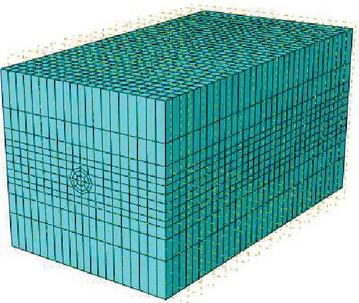
Figure 2 Model grid division.
The Temporal and Spatial Evolution Law of Mechanical Characteristics of Hydraulic Tunnels With High Ground Temperature
In order to comprehensively analyze the temporal and spatial distribution of mechanical characteristics of surrounding rock with high ground temperature during construction, six locations with the distances of 0 m, 10 m, 20 m, 30 m, 40 m, and 50 m from the excavation face were selected in this section based on the results of numerical simulations. The trends of the displacement and plastic strain of the surrounding rock top arch, waist arch and plastic strain of high ground temperature hydraulic tunnel at different excavation depths were analyzed. At the same time, in order to accurately analyze the distribution of the mechanical characteristics during the completion of the construction of the surrounding rock with high ground temperature, the numerical simulation cloud diagram 130 days after the construction of the surrounding rock was analyzed.
Temporal and Spatial Evolution of Surrounding Rock Displacement
The temporal and spatial evolution law of the surrounding rock displacement of 0 m, 10 m, 20 m, 30 m, 40 m, 50 m away from the excavation face was numerically simulated. In addition, the displacement distribution cloud map of the surrounding rock 130 days after excavation was obtained. The results are shown in Figures 3 and 4.
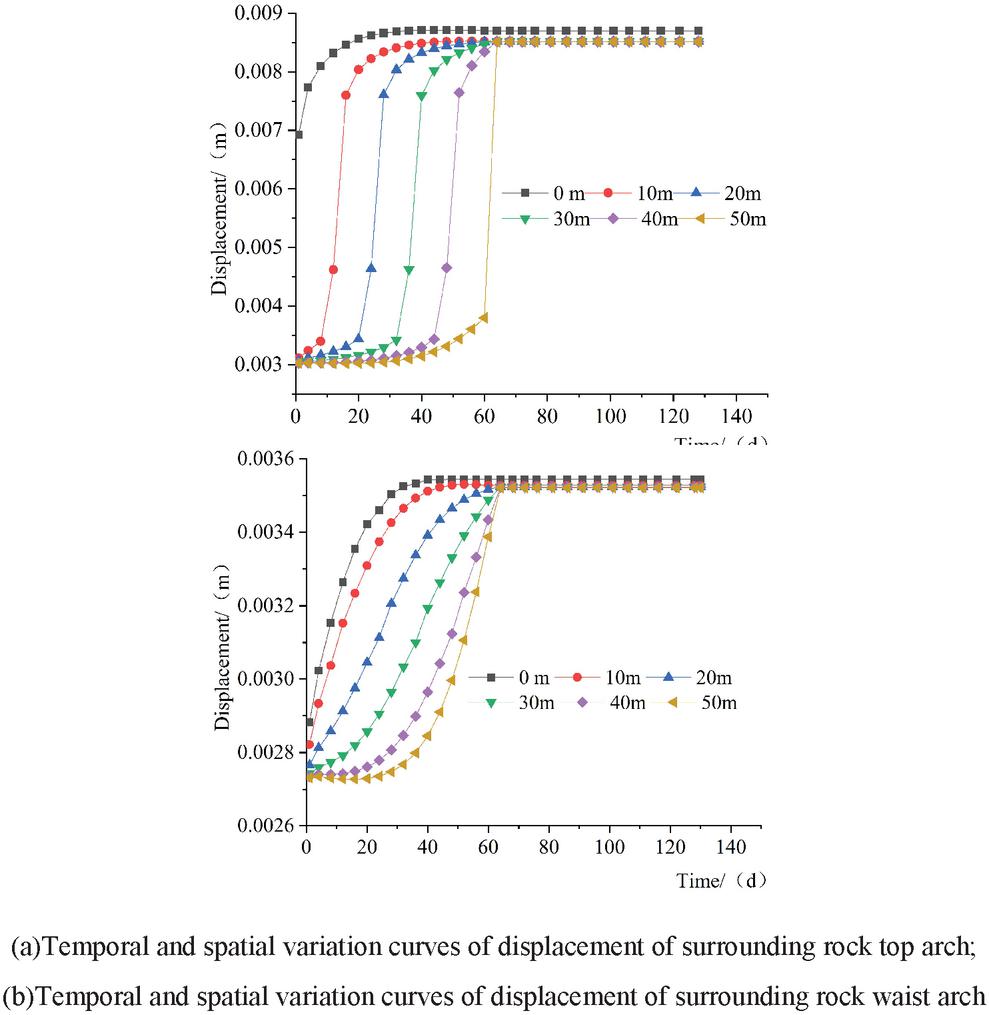
Figure 3 Temporal and spatial variation curve of surrounding rock displacement at different excavation depths.
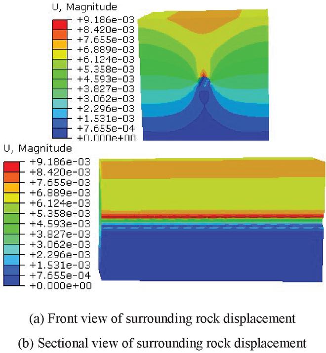
Figure 4 Displacement cloud map of surrounding rock.
It can be seen from Figure 3(a) that the displacements at different excavation depths of the tunnel top arch increase with time. As time increases, the displacement gradually tends to a steady state. The analysis showed that the rock mass was damaged by excavation disturbance at the initial stage of excavation, which caused the displacement of the rock mass at the moment of excavation. The initial value of the arch displacement at the tunnel entrance was relatively large, with the value of 0.0069 m. The maximum displacement at the tunnel entrance can reach 0.0087 m. The initial displacement of the tunnel at the excavation depths of 10 m, 20 m, 30 m, 40 m and 50 m was about 0.0030 m. The maximum displacement was about 0.0085 m. The top arch of the tunnel was more significantly affected by excavation than other locations in the tunnel. There was an inflection point of sudden increase in the top arch displacement of the tunnel on the 12th day at the excavation depth of 10 m, on the 24th day at 20 m from the tunnel, the 36th day at 30 m from the tunnel, the 48th day at 40 m from the tunnel, and the 62nd day at 50 m from the tunnel. Based on this pattern, it is possible to estimate the progress of the excavation of the surrounding rock.
It can be seen from Figure 3(b) that the displacements at different excavation depths of the top of the tunnel gradually increase with time. As time increases, the displacements tend to stabilize. The displacement of the waist arch of the tunnel entrance was larger than that of other positions at the same the depth of the tunnel. The initial displacement of the waist arch was 0.0029 m, and the maximum displacement can reach 0.0035 m. Comparing Figures 3(a) and 3(b), we can see that the displacement of top arch and waist arch have almost the same trends over time, but the top arch displacement is relatively larger. In addition, at the excavation depths of 10 m, 20 m, 30 m, 40 m and 50 m, a sudden increase in stress occurred at all locations of the top arch, while the stress in the waist arch maintained a continuous and steady growth trend. The result indicated that the excavation disturbance had a greater impact on the top arch of the surrounding rock and relatively little impact on the waist arch of the surrounding rock. During the construction of hydraulic tunnels with high ground temperature, corresponding measures should be taken to ensure the stability of the rock mass.
Figure 4 is a displacement cloud map of the surrounding rock. It can be seen from Figure 4(a) that the surrounding rock displacement is almost evenly distributed. In general, the displacement is larger in the upper part of the surrounding rock and smaller at the bottom part of the surrounding rock. The analysis showed that there was almost no displacement at the bottom of the surrounding rock, which was mainly due to the setting of hinge constraints at the bottom of the surrounding rock model to ensure that the rock mass model was consistent with the actual project. The displacement at the top of the tunnel was the largest, with the maximum value of 0.0091 m. Thus, the top of the tunnel was greatly affected by the excavation. It can be seen from Figure 4(b) that the overall axial displacement distribution of the surrounding rocks along the tunnel remains almost constant, which indicates that the axial displacement inside the rock mass increases with the excavation time and remains at the same value in the end.
Temporal and Spatial Evolution of Plastic Strain of Surrounding Rock
Based on the numerical simulation results, the temporal and spatial variation curves of the plastic strain of the surrounding rock top and waist arches at the excavation depths of 0 m, 10 m, 20 m, 30 m, 40 m, and 50 m were obtained. In addition, the cloud map of the plastic strain distribution of surrounding rock 130 days after excavation was obtained. The results are shown in Figures 5 and 6.
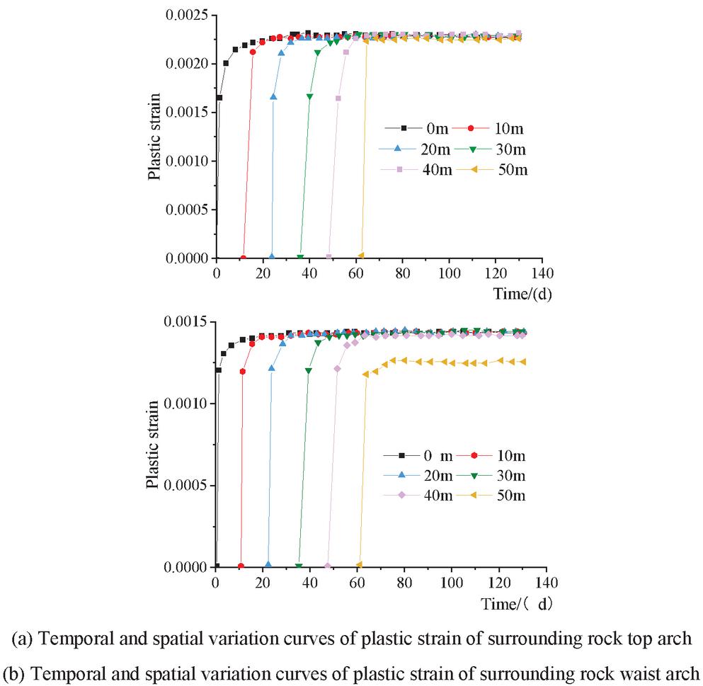
Figure 5 Temporal and spatial variation curves of plastic strain of surrounding rock at different excavation depths.
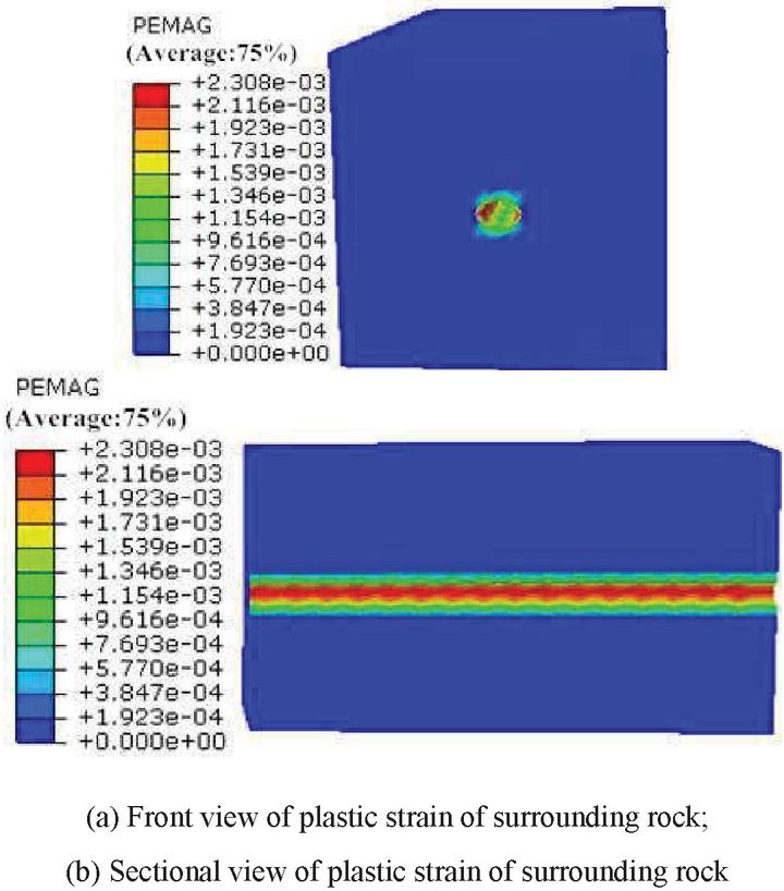
Figure 6 Plastic strain cloud diagram of surrounding rock.
It can be seen from Figure 5(a) that the plastic strain of the surrounding rock top arch has an overall increasing trend with time, and the plastic strain value gradually stabilizes with the increase of time. At the excavation depth of 50 m, the plastic strain value of the tunnel excavation was relatively small, while the maximum plastic strain value of other parts in the tunnel was about 0.0014. Thus, the plastic strain value of the top arch of the tunnel was relatively small. It is necessary to adopt measures to reduce the plastic strain of other parts of the tunnel. From Figure 5(b), the plastic strain of the surrounding rock waist arch increases with time, and the plastic strain value gradually stabilizes with the increase of time. The maximum plastic strain value was 0.0023. Compared with the plastic strain of the top arch of the surrounding rock, the plastic strain of the waist arch of the surrounding rock was larger and the plastic strain at different excavation depths was basically the same. Therefore, in order to ensure the stability of the tunnel, it is necessary to consider adding bolts or laying a reinforced network to reduce the plasticity of the tunnel waist arch.
Comparing the temporal and spatial changes in displacement and plastic strain of the surrounding rock of a hydraulic tunnel with high ground temperature, it can be seen that the displacement of the top arch and waist arch of the tunnel was immediately produced at the moment of excavation, while plastic strain began to occur at 0 m from the tunnel entrance on the 0th day, at 10 m on the 12th day, at 20 m on the 24th day, at 30 m on the 36th day, at 40 m on the 48th day, and at 50 m on the 62nd day. Therefore, the occurrence of plastic strain was closely related to excavation disturbance. During the excavation process, the surrounding rock only produced plastic strain on the excavated face, and the unexcavated rock mass was not damaged, so the corresponding plastic range did not occur. The plastic strain and displacement had a same temporal and spatial variation law that the trend of plastic strain with time was consistent with the trend of surrounding rock top arch displacement. This variation law of the plastic strain and top arch displacement can characterize the excavation process.
Figure 6 is the plastic strain cloud diagram of the surrounding rock. From Figure 6(a), the plastic zone of the surrounding rock is approximately circular, and the entire plastic zone is concentrated 3 m from the tunnel entrance. According to the distribution of the plastic zone, it can be seen that the plastic zone of the top and bottom arches of the surrounding rock is larger, while the plastic zone of the waist arch of the surrounding rock is smaller. According to the plastic strain value, the plastic strain of the top and bottom arches of the surrounding rock is smaller, while the plastic strain at the waist arch of the surrounding rock is relatively larger. Therefore, it is necessary to take measures to reduce both the range of the plastic zone and the plastic strain value to ensure the stability of the surrounding rock during on-site construction. From Figure 6(b), the plastic zone of the surrounding rock waist arch is the largest, and the maximum plastic strain value is 0.0023. The plastic zone at the waist arch of the tunnel is wavy. This is because when the numerical model is established, numerical modeling of the excavation simulation in analytical steps leads to a regular wavy distribution of plastic zones at the waist arch of the surrounding rock along the tunnel axis.
Analysis of On-Site Monitoring Results
Monitoring Program of Surrounding Rock Displacement
According to the purpose of the analysis, in order to fully understand and analyze the temporal and spatial evolution of the mechanical characteristics of a hydraulic tunnel with high ground temperature during the construction, the displacement of the surrounding rock of a hydraulic tunnel with a high ground temperature in Xinjiang was monitored during the construction. The engineering grade of the surrounding rock was Class III, the buried depth of surrounding rock was 370 m, and the tunnel diameter was 3.0 m. Multi-point displacement meters were arranged at the section of the entrance of the surrounding rock cave to monitor the displacement changes at 0 m, 2 m, and 5 m away from the tunnel wall. The internal layout of measurement points of the surrounding rock at the monitoring section is shown in Figure 7.
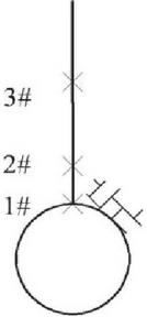
Figure 7 Layout of measurement points for surrounding rock displacement.
Analysis of Monitoring Results
Based on the on-site monitoring results, the on-site monitoring results at the 1# and 2# measurement points were extracted. The temporal and spatial variation of the displacement is shown in Figure 8. At the same time, for comparison and analysis, the variation of top arch displacement of the corresponding tunnels by the numerical simulation model was added in the figure.
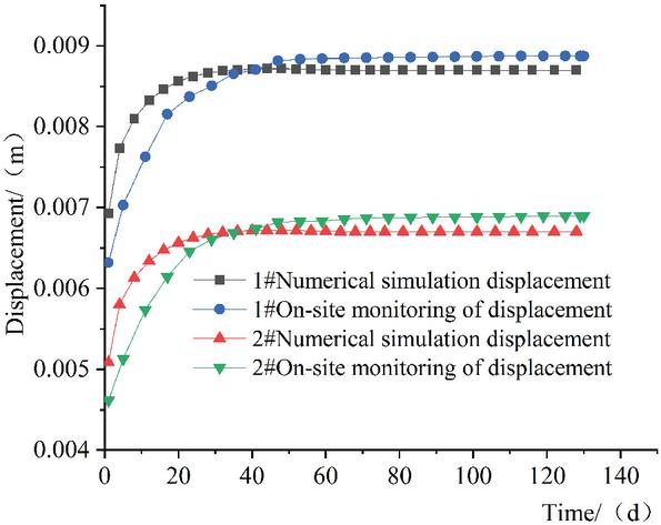
Figure 8 Numerical simulation result and on-site monitoring data of the displacement at measuring points 1# and 2# in the surrounding rock top arch.
It can be seen from Figure 8 that at 1# measurement point, the maximum displacement from the numerical simulation is 0.0087 m, and the maximum displacement from field monitoring is 0.0089 m. At 2# measurement point, the maximum displacement from numerical simulation is 0.0067 m, and the maximum displacement from field monitoring is 0.0069 m. Both numerical simulation result and on-site monitoring data of the displacement at 1# measurement point are larger than those at 2# measurement point, that is, the displacement at the top of the tunnel is larger. Thus, the displacement at the top of the tunnel was greatly affected by the excavation. According to the variation of displacement with time, the numerical simulation results and on-site monitoring results of the 1# and 2# measurement points stabilized in about 36 days after excavation. Combing with the analysis step in the numerical simulation model and the actual engineering excavation time, it can be obtained that the excavation depth of the tunnel was approximately 12 m at this time. On that basis, it can be inferred that the impact range of the surrounding rock construction was approximately 12 m, which can provide a reference for the formulation of actual construction plans.
Analysis of Mechanical Characteristics of Hydraulic Tunnels With High Ground Temperature Based on Different Construction Methods
In actual projects, the lining structure is used as the foundation of tunnel water delivery and considered an important part of tunnel construction. The temporal and spatial evolution of the mechanical characteristics of the surrounding rock during the excavation of a high ground temperature hydraulic tunnel was studied, and the temporal and spatial evolution laws of the displacement from both numerical simulation and on-site monitoring were compared. Based on the results, we demonstrated that the mechanical characteristics during the construction period by the numerical model were consistent with that in the actual project. Therefore, in this section, taking an existing hydraulic tunnel project in Xinjiang as the research background, according to the relevant on-site measurement data, two different construction methods, i.e., the lining applied after tunnel excavation and the parallel construction of excavation and lining, were numerically simulated. The mechanical characteristics of the surrounding rock and lining structure of the tunnel under different construction methods were analyzed.
Model Parameter Selection and Grid Division
The parameters and size of surrounding rock model were the same as those in the first section. The engineering grade of surrounding rock was set to Class III, the tunnel excavation and lining duration was 130 days, the excavation length was 50 m, the buried depth of surrounding rock was 370 m, and the role of groundwater in the overlying rock mass was not considered. The tunnel diameter was 3.0 m, and the calculation range of the surrounding rock model was 33 m * 33 m. The C25 concrete lining was adapted, and the lining thickness was 0.5 m. The size of the lining model is shown in Figure 9, and the thermodynamic parameters are shown in Table 2. In the analysis, two construction methods were adopted, i.e., lining immediately after excavation and parallel construction of excavation and lining.
Table 2 Mechanical and thermal parameters of lining
| Temperature/C | Elastic Modulus/ GPa | Thermal Conductivity/ W/(mC) | Linear Expansion Coefficient/ C | Specific Heat Capacity/ J/KgC | Poisson’s Ratio | Internal Friction Angle/ | Cohesion/ MPa |
| 20 | 30.0 | 1.69 | 1.00 | 913 | 0.167 | 54 | 2.42 |
| 35 | 29.6 | 1.68 | 1.01 | 916 | 0.167 | 54 | 2.42 |
| 50 | 29.1 | 1.67 | 1.01 | 920 | 0.167 | 54 | 2.42 |
| 65 | 28.9 | 1.66 | 1.02 | 923 | 0.167 | 54 | 2.42 |
| 80 | 28.7 | 1.65 | 1.03 | 926 | 0.167 | 54 | 2.42 |
| 95 | 28.4 | 1.64 | 1.03 | 929 | 0.167 | 54 | 2.42 |
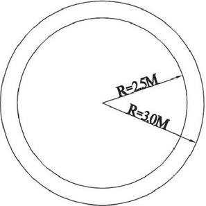
Figure 9 Plan dimensions of the lining model.
Considering that the hydraulic tunnel was a section with high ground temperature, the high ground temperature diversion tunnel model adopted a transient temperature-displacement coupling model, and a direct coupling method was used to simulate the construction process of high ground temperature rock masses. The temperature boundary conditions were based on on-site monitoring results. The temperature of the original rock was 80C, and the surrounding rock was ventilated after excavation at the ventilation temperature of about 25C. Thus, the boundary condition of surrounding rock temperature was set to 80C, the forced convection heat transfer coefficient between surrounding rock and air after excavation was set to 30 W/(mC), and the forced convection heat transfer coefficient between concrete and air was 45 W/(mC). During the excavation of the rock mass, the rock mass was ventilated and cooled at the same time. The ambient temperature of the rock mass was 25C. During the lining process, the influence of the concrete hydration heat on the rock mass was not considered, and the tunnel was continuously ventilated. The ambient temperature of the lining was 20C. The surrounding rock grid attribute adopted C3D8T eight-node thermally coupled hexahedral element, three-direction linear displacement, three-direction linear temperature, and the number of grid units was 8848. The lining grid attribute adopted C3D8T, and the number of grid units was 1872. The grid division of lining model is shown in Figure 10.

Figure 10 Grid division of lining model.
Mechanical Characteristics of Hydraulic Tunnels With High Ground Temperature Under Different Construction Methods
In order to compare and analyze the mechanical characteristics of hydraulic tunnels with high ground temperature under different construction methods, the mechanical characteristics of the surrounding rocks at the tunnel opening section were compared and analyzed under the pure excavation construction method, the lining construction method immediately after excavation, and the parallel excavation and lining construction method.
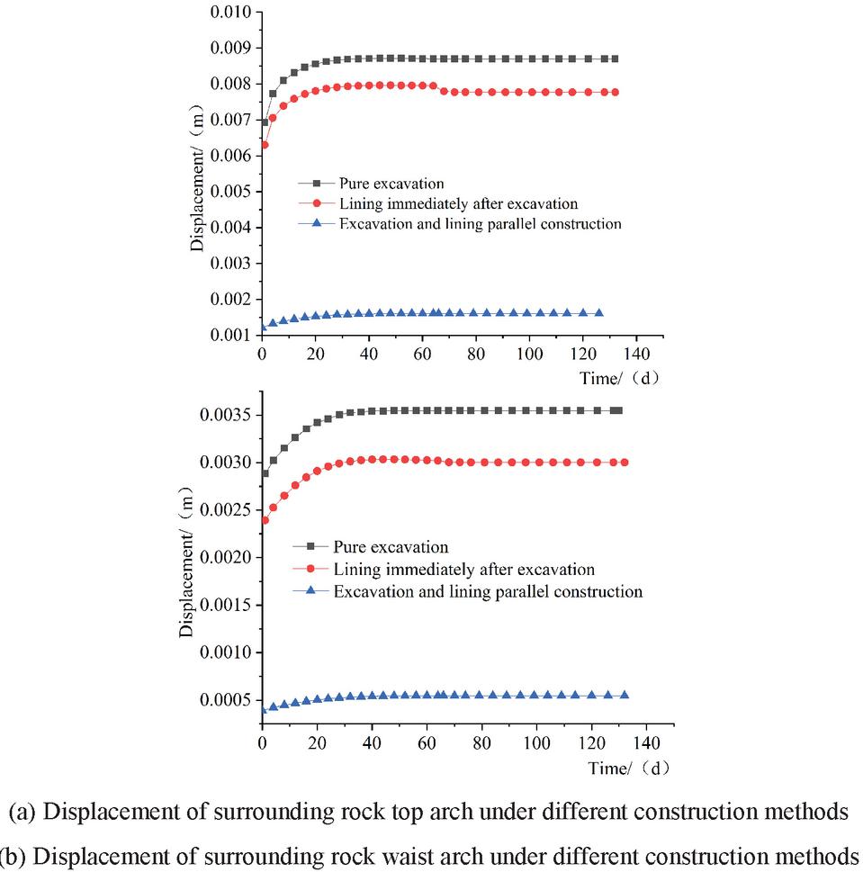
Figure 11 The variation law of surrounding rock displacement under different construction methods.
Variation Law of Surrounding Rock Displacement Under Different Construction Methods
Figure 11 shows the temporal and spatial variation of surrounding rock displacement under different construction methods. Under the three different construction methods, the displacement of tunnel openings increases with time. Among them, the displacement of the surrounding rock top arch during the pure excavation of the tunnel was the largest. The analysis of Figure 11(a) shows that the pure excavation produces the largest displacement, which can reach 0.0087 m. In the pure excavation process, the displacement gradually increases with time and tends to a stable state. In the method of lining immediately after excavation, the top arch displacement is smaller than the pure excavation construction method, and the maximum displacement is 0.0080 m. The displacement initially increases with the time, and then decreases to a certain extent when the lining is applied on the 68th day of construction. At this time, the excavation has been completed and the lining has been applied to different sections of the rock mass. Thus, lining the rock mass can reduce the displacement. The displacement caused by the parallel construction method of excavation and lining was the smallest, and the maximum displacement was 0.0016 m, which indicated that the parallel construction of tunnel excavation and lining had little effect on surrounding rock. Comparing Figures 11(a) and 11(b), it can be seen that the displacement of surrounding rock top arch is greater than the displacement of waist arch under different construction methods. Moreover, under the construction method of lining immediately after excavation, the reduction in the top arch displacement by lining is more obvious than the waist arch displacement, indicating that all construction methods have more significant impact on the surrounding rock top arch than the waist arch.
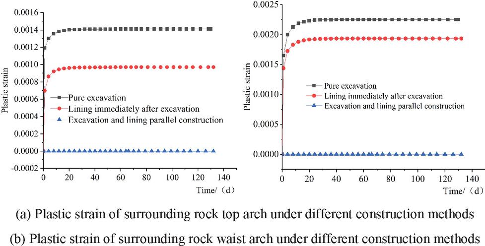
Figure 12 Variation law of plastic strain of surrounding rock under different construction methods.
Variation Law of Plastic Strain of Surrounding Rock Top Arch Under Different Construction Methods
Figure 12 shows the variation of the plastic strain of surrounding rock over time under different construction methods. Under all the three different construction methods, the plastic strain of the tunnel entrance increases with time. Among them, the plastic strain of the surrounding rock top arch was the largest during the pure excavation, while the plastic strain was the smallest during the parallel construction of the excavation and the lining. The analysis of Figure 12(a) shows that pure excavation construction produces the largest plastic strain with the maximum value of 0.0014, and its plastic strain gradually increases with time and eventually stabilizes. In the method of adding lining immediately after excavation, the plastic strain of the top arch is relatively smaller than that in the pure excavation construction method, and the maximum plastic strain is 0.00097. Its plastic strain also gradually increases with time and tends to a stable state. In the parallel construction method of excavation and lining, the plastic strain is zero. Comparing Figures 12(a) and 12(b), it can be seen that the plastic strain of the surrounding rock construction top arch under different construction methods is less than the plastic strain of the waist arch, while the parallel construction of excavation and lining does not produce plastic strain on the top arch and the waist arch of surrounding rock. According to the numerical simulation results, the plastic strain is borne by the lining structure. This is due to the high strength of the surrounding rock and the large thickness of the lining structure in the simulation of the parallel excavation and lining construction method. These two factors greatly reduce the impact of excavation on surrounding rock.
Conclusions
(1) The displacements of the top arch and waist arch of the tunnel increased with time. The top arch of the tunnel had the largest displacement and the maximum displacement was 0.0091 m. The top arch of the tunnel entrance was more affected by excavation than other locations in the tunnel. Corresponding reinforcement measures must be taken to ensure the stability of the surrounding rock.
(2) The plastic zone of the surrounding rock waist arch was the largest, and the maximum plastic strain was 0.0023. The plastic zone of the top and bottom arches of the surrounding rock was larger, while the plastic zone of the waist arch was smaller. The plastic strain of the top and bottom arches of the surrounding rock was smaller, while the plastic strain of the surrounding rock waist arch was larger. At the same time, it is necessary to take measures to reduce the plastic zone and the plastic strain to ensure the stability of the surrounding rock.
(3) The displacement of the top arch had a sudden inflection point on the 12th day at the excavation depth of 10 m, the 24th day at 20 m, the 36th day at 30 m, the 48th day at 40 m and the 62nd day at 50 m. In addition, the plastic strain was generated at the same position and at the same time. According to the variation laws of displacement and plastic strain, the excavation progress of the surrounding rock can be inferred, and a reasonable support time can be selected.
(4) The displacement and plastic strain produced by the parallel construction of excavation and lining were less than the construction method of lining after excavation, and the displacement and plastic strain produced by the construction method of lining after excavation were less than the construction method of pure excavation. The parallel construction method of lining construction had little impact on the surrounding rock. This construction method can be used when the surrounding rock has good mechanical properties and the construction period is urgent.
Acknowledgments
This work was financially supported by the National Natural Science Foundation of China (Grant No. 51769031) and Regional innovation Guidance Plan project of the XPCC (Grant No. 2021BB004).
References
[1] GONG Jianwu, QI Peilin. Research on Construction Time-space Characteristic of Three-lane Tunnel with Extra-close Spacing[J]. Highway, 2016, 61 (08), 217–221.
[2] WANG Yunfei, ZHENG Xiaojuan. Mechanical and Deformation Property and Acoustic Emession Characteristics of Coal Rock Under Unequal Bilateral Confining Pressure [J]. Industrial Construction, 2014, 44 (11), 112–118.
[3] SI Jianqiang, ZHU Guojin, LI Yun. Research on the spatiotemporal effect of excavation and support of deep buried soft rock water-conveyance tunnel [J]. Yangtze River, 2016, 47 (S1), 154–157.
[4] FAN Chengyu, LI Zhida, LIU Zihang. Optimization of construction and analysis of mechanical characteristics of the entrance section of Wufeng Mountain Tunnel [J]. Engineering and Construction, 2019, 33(06), 977–983.
[5] YANG Yongwei. Research on the influence of the new tunnel in the Overlapping Tunnel on the mechanical characteristics of the existing tunnel [J]. Gansu Water Resources and Hydropower Technology, 2019, 55 (12), 29–33.
[6] YANG Chunshan, WEI Lixin, MO Haihong, et al. Mechanical properties and influencing factors of multi-layer composite lining of shield tunnel [J]. Journal of Hefei University of Technology (Natural Science), 2019, 42(10), 1368–1374.
[7] LI Ru. Study on Numerical Simulation and Cooling Technology of Construction Ventilation in High-temperature Ground Tunnels [D]. Henan Polytechnic University, 2018.
[8] LIU Jinsong. Study on the key technology of high geothermal tunnel construction on Sichuan-Tibet Railway [J]. Construction Technology, 2018, 47(01), 100–102.
[9] LI Songlei, WANG Jincheng, QIN Yulong, et al. Surrounding rock temperature-stress analysis and construction countermeasures of deep buried tunnel under high ground temperature [J]. Water Resources and Hydropower Engineering, 2017, 48(10), 80–86.
[10] Duolei Kuai. Distribution Law of Three Spontaneous Combustion Zones in the Goaf Area of a Fully Mechanized Working Face under High Ground Temperature. [J]. Environmental and Earth Sciences Research Journal, 2021, 8(02), 86–190.
[11] GAO Ping. Analysis of rock thermal physical parameters and research on multi-field thermal effect coupled model [D]. Jilin: Jilin University, 2015.
[12] MENG Yao, JIANG Haibo. The distribution law of surrounding rock temperature field of a hydraulic tunnel in cold region based on convection – conduction coupling model [J]. Journal of Water Resources & Water Engineering, 2020, 31(01), 221–226.
[13] ZHANG Yuan. Transient Temperature Field of Surrounding Rock of the High Geothermal Roadway and Its Heat Control Mechanism by Heat Insulation[D]. Xuzhou: China University of Mining and Technology, 2013.
[14] ZHANG Yuan, WAN Zhi-Jun, ZHOU Chang-Bing, et al. Spatial-temporal distribution characteristics of surrounding rock temperature in high geothermal roadway [J]. Disaster Advances, 2013, 6(S5), 103–109.
[15] WANG Yijiang. Heat and mass transfer of surrounding rock and airflow for deep thermal environment [D]. Xuzhou: China University of Mining and Technology, 2010.
[16] GUO Qinglu, RONG Guan, YAO Mengdi, et al. Experimental study on mechanical properties of thermal damage acoustic emission of marble [J]. Chinese Journal of Rock Mechanics and Engineering, 2015, 34(12), 2388–2399.
[17] WANG Mingnian, HU Yunpeng, TONG Jianjun, et al. Experimental study on shear mechanical properties and thermal damage model of shotcrete-rock interfaces under variable high temperatures[J]. Chinese Journal of Rock Mechanics and Engineering, 2019, 38(1): 63–75. (in Chinese)
[18] YAN Jian, HE Chuan, WANG Bo, et al. Inoculation and characters of rockbursts in extra-long and deep-lying tunnels located on Yarlung Zangbo suture[J]. Chinese Journal of Rock Mechanics and Engineering, 2019, 38(4):769–781. (in Chinese)
[19] PETER K, KAISER, Cai Ming. Design of rock support system under rock burst condition [J]. International Journal of Rock Mechanics and Mining Sciences, 2012, 4(3): 215–227.
[20] WANNE T S, YOUNG R P. Bonded-particle modeling of thermally fractured granite [J]. International Journal of Rock Mechanics and Mining Sciences, 2008, 45(5): 789–799.
[21] ANDERSSON J CHRISTER, MARTIN C DEREK. The Äspö pillar stability experiment: Part II-Rock mass response to coupled excavation-induced and thermalinduced stresses[J]. International Journal of Rock Mechanics and Mining Sciences, 2009, 46(5): 879–895.
[22] KWON S, CHO W. J. The influence of an excavation damaged zone on the thermal-mechanical and hydro-mechanical behaviors of an underground excavation[J]. Engineering Geology, 2008, 101(3): 110–123.
[23] LI S. Y. LAI Y. M, ZHANG S. J. An improved statistical damage constitutive model for warm frozen clay based on Mohr-Coulomb criterion[J]. Cold Region Science and Technology, 2009, 57(2): 154–159.
Biographies

Haijuan Wang received bachelor’s degree and her master’s degree. Bachelor of Engineering, Agricultural Water Conservancy Engineering, Hebei University of Engineering (former North China Institute of Water Conservancy and Electric Power); 2010 Northwest A&F University, Master of Engineering, Water Conservancy and Hydropower Engineering. Since 2010, he has been working as an associate professor in School of Water Conservancy and Construction Engineering, Shihezi University. Research direction: water conservancy and hydropower, hydraulic structure engineering.

Haibo Jiang is a Ph.D. student at the Xinjiang Agricultural University in China since spring 2008, received doctorate degree in water conservancy and hydroelectric engineering in 2011. Haibo Jiang Ph.D. work centers on Seepage prevention technology of plain reservoir and discusses the Seepage prevention technology of plain reservoir to develop new theories and methods. Scientific research is mainly carried out on the prevention and control of freezing damage of hydraulic materials and water engineering in cold areas, hydraulic structure performance, stress and deformation of rock and soil mass and disasters, etc., with obvious characteristics in multi-field coupling effect of hydraulic structure, freeze-thaw damage and damage mechanism of rock and soil mass, as well as the coupling mechanism of frost resistance, heat insulation and mechanics of hydraulic materials.

Fengchun Yang received bachelor’s degree and master’s degree. 2013 Xi’an University of Technology, Bachelor of Engineering; 2017 Xi’an University of Technology, Master of Engineering in Geotechnical Engineering. Since 2017, has been teaching and associate professor at School of Water Conservancy and Construction Engineering, Shihezi University. His research direction is hydraulic geotechnical engineering in cold and arid areas.
European Journal of Computational Mechanics, Vol. 30_2-3, 145–168.
doi: 10.13052/ejcm1779-7179.30231
© 2021 River Publishers