Direct Actuation of Large Sized Valves by a Hydraulically Relieved Electromechanical Actuation System
Tobias Vonderbank*, Pierre Marc Laßl Chavez and Katharina Schmitz
Institute for Fluid Power Drives and Systems (ifas), RWTH Aachen University,
Aachen, Germany
E-mail: tobias.vonderbank@ifas.rwth-aachen.de
*Corresponding Author
Received 31 August 2021; Accepted 30 September 2021; Publication 12 November 2021
Abstract
Extensive actuation forces and strokes are required for the actuation of large sized valves normally implemented in high power hydraulic systems. A hydraulically piloted operation is, for now, the most suitable solution and state of the art. However, there are some applications where electromechanical valve actuation systems are at advantage against common pilot operation systems. In this contribution it is analyzed in which cases the application of electro-mechanical actuators can be of advantage and why displacement-controlled systems may be one of these applications. A novel electromechanical valve actuation system for large sized 4/3-way directional control valves for the use in displacement-controlled systems is presented. This new actuation system is characterized by a hydraulic relief of the centering springs. Therefore, the springs are only active in safety-critical conditions, such as a power outage. Since the actuator is not working against the spring force during every displacement, the necessary actuation force is reduced drastically. Thus, common electromechanical actuators can be used. In case of a power outage, the spring relief is deactivated causing the stored energy to center the spool in its neutral position. The performance of the novel actuation system is examined through measurements conducted on a manufactured demonstrator for valves of nominal size 25 with a flow rate of up to 600 l/min.
Keywords: Electromechanical actuation system, large sized valves, valve actuation system, pilot operation, flow controlled system.
1 Introduction
Directional control valves are used to open or close flow paths of hydraulic systems [1–3]. Valves can be distinguished in their design (spool or seat valve), their adjustment (switching or proportional) and their actuation system [2]. To ensure the interchangeability of different valves the International Organization for Standardization has defined the dimensions and other specifics for mounting surfaces of four-port hydraulic directional control valves in the ISO 4401 [4]. This standard specifies six different nominal sizes with corresponding mounting surfaces, which are distinguished by the position of the port holes and their maximum diameter. For industrial valves it is common practice that valves are classified by their respective nominal size.
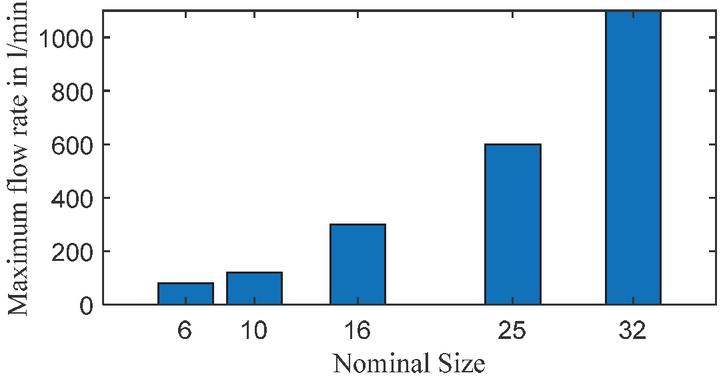
Figure 1 Maximum flow rate of a specific valve series over their nominal size [5].
The mounting surface for valves of nominal sizes 4, 6, 10, 16, 25 and 32 corresponds to the six surfaces defined in ISO 4401. Valves of large nominal sizes possess higher port diameters and therefore allow higher flow rates. This correlation can be seen in Figure 1. The maximum possible flow rate of a specific valve series is displayed over the corresponding nominal size. Since the cross-section increases quadratically with the increment of the port’s inner diameter there is, under assumption of a constant maximum flow velocity, an approximately quadratic progression between the nominal size and the maximum flow rate.
Spool valves with a maximum flow rate larger than 80 l/min, which in practice are usually valves of nominal size 16 and larger, are normally actuated by a hydraulic pilot valve [1]. The performance of the whole actuation system depends on the pilot valve’s hydraulic supply. Therefore, when using pilot operated valves special attention must be paid to the system design. In general, the pilot circuits can be supplied internally or externally by a separate hydraulic circuit. The corresponding system can be most basic, like shown in Figures 2 and 3.
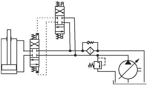
Figure 2 Basic system for internal supply.
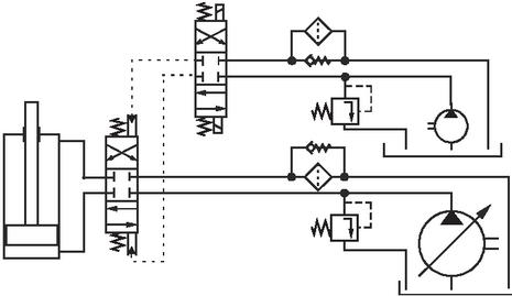
Figure 3 Basic system for external supply.
An external supply is essential for faultless operation if the pressure in the hydraulic main circuit can drop below a critical value. In the technical literature, reference is made to a necessary minimum pressure of around 4 to 5 bar [1, 6]. Depending on the valve, this value is sometimes even higher, reaching values around 12 bar [5, 7]. The most basic external pilot circuit consists of a fixed displacement pump, which supplies the pilot valve with a constant flow rate. In these systems the pilot flow rate which is not required is throttled back against the tank at system pressure over the pressure relief valve. Depending on the operation of the system, this can lead to large loses. By the integration of an accumulator and a corresponding accumulator-sense pump-unloading valve these loses can be reduced drastically. Therefore, the pump is unloaded to pressureless circulation when the accumulator pressure is within a specified range. The system then is fed by the accumulator. This way, only the required flow rate is provided at the desired system pressure [8].
Even though the efficiency can be improved using more complex pilot circuits like previous explained accumulator-sense pump-unloading systems, a trade-off between efficiency and effort must be made. In some cases the application of electromechanical actuators, which represent a cost-effective alternative to hydraulic pilot systems, may be another way to increase the efficiency. However, the necessary forces and large strokes, which are required for larger valves, are challenging for common electromechanical actuators like solenoids. Therefore, not every substitution of a hydraulic pilot circuit by an electromechanical actuation system is beneficial and each case must be individually assessed.
2 Actuation Forces
With hydraulic linear actuators large forces can be applied [3, 6, 9, 10]. They are therefore suitable for linear positioning tasks, such as the switching of a spool valve. In fact, the maximum achievable force of the pilot operation normally exceeds the necessary forces by far. Even if the pilot operation of common nominal size 25 valves requires a minimum operation pressure between 5 and 12 bar [5, 7] they often can be operated with pressures up to 350 bar [11]. Considering a valve spool diameter of 35 mm, as a representative value, forces between 481 N and 33.7 kN are possible. In case of an electromechanical actuation system, such oversizing would lead to disproportionately large and thus very expensive actuators. To prevent any over- or undersizing, the counteracting forces, which are shown in Figure 4, must be investigated with in detail.
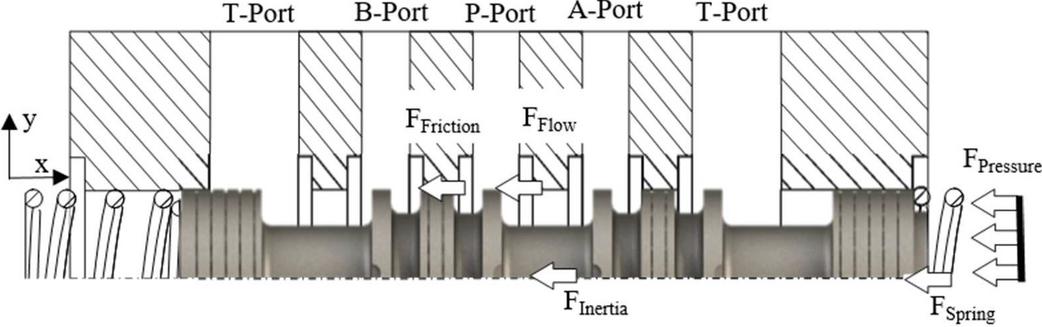
Figure 4 Applied forces on the spool according to [12–16].
Beside spring forces F, friction forces F, interial forces F and flow forces F resulting from the deflection of the flow, which passes the valve, an additional force F, resulting from resistances in the pilot drain line needs to be overcome in the case of hydraulic pilot operation. The magnitude of this force depends on the surface area of the spool, the speed of the spool and the design of the pilot circuit drain line. Therefore, the resulting counteracting force F highly depends on the system and only occurs in pilot operated systems which is why this force does not have to be considered during the design of electromechanical actuation systems. However, care should be taken to ensure that the two pilot chambers are pressure balanced, or the design of the valve housing should be adapted accordingly [17, 18]. When considering the remaining forces, the flow and spring forces are usually dominant, while friction and inertial forces are comparatively low [19].
2.1 Flow Forces
The flow forces can be derived analytically from the momentum theorem in the spool chamber. Exemplary Figure 5 shows one control volume for the investigated valve. The oil with a flow rate Q enters the control volume at the P-port with a velocity v under an angle of and leaves the system with a velocity v under an angle of at the Port A.
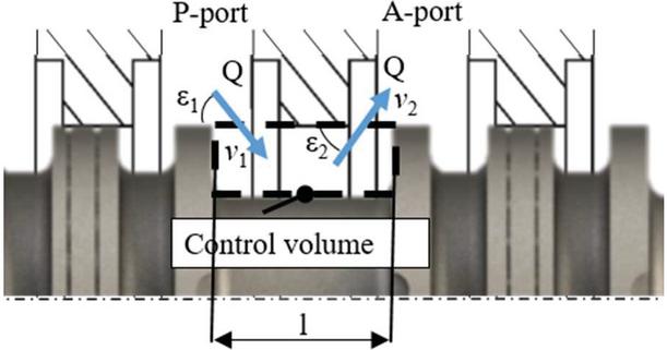
Figure 5 Control volume of flow forces according to [20–22].
Based on the conservation of momentum the flow force can be calculated with Equation (1), as a function of the angles and , the density , the cross-section A, the flow rate Q, their time derivation dQ/dt and the length of the valve chamber l. The flow force can be divided into a steady state term and a transient term [19, 20, 23].
| (1) |
Transient flow forces results out of the acceleration and deceleration of the fluid in the valve chamber. Del Vescovo has analyzed the transient flow forces acting on a directional valve. He proved that the hypothesis of quasi-stationarity can be considered as valid for valves with opening velocities lower than 0.1 m/s [24]. Since no fast switching valves are considered in this paper and this assumption can therefore be considered as valid, the following analyses focus on the steady state flow forces, whereas the transient are neglected. Formula (1) will be simplified by the omission of the last term.
For a small valve displacement the cross-section A is accordingly large in comparison to A. Therefore, the velocity at the P-port is smaller than the velocity at the A-Port. Due to the large opening, the angle is generally assumed to be 90, which simplifies the equation of the steady state flow force by disregarding the first term [20, 23]. However, this commonly used simplification can not be considered valid in the presented case, since the areas A and A are of same magnitude for large openings. Considering that a flow also passes the valve from the second port B to the tank port T, the equation for the steady state flow force must be extended by two additional terms to represent the total steady state flow force. Here, it should be noted that the directions of steady state flow forces depend on the geometrical design of the spool and the housing, as well as on the direction of the flow rate. For the spool shown in Figure 4, Equation (2) is obtained by considering a spool position as shown in Figure 5. Here the indices refer to the corresponding valve port.
| (2) |
Since the flow angles are usually unknown, these formulas can often only be used for an estimation of the steady state flow force, and are therefore not suitable for applications where an accurate calculation of flow forces is required, as, e.g., for the design of electromechanical valve actuations systems. Therefore, the design of optimized electromechanical actuation systems requires a measurement of the flow forces or their calculation by Computational Fluid Dynamics (CFD). As the steady state flow forces depend not only on the valve geometry and the spool position, but also on the passing flow rate, the subsequent application of the valve needs to be considered during the design process. It should also be taken into account that the necessary forces can vary considerably depending on the operating profile of the hydraulic system. To investigate the application potential of electromechanical actuation systems, the steady state flow forces acting on the spool of a 4/3 directional control valve of nominal size 25 have been analyzed with measurements carried out at a test rig, which was built at ifas laboratory, according to the circuit diagram in Figure 6.
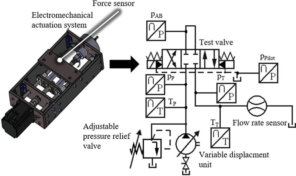
Figure 6 Circuit diagram of the test rig and electromechanical actuation system (displacement sensor not depicted).
The test rig is supplied with hydraulic power by a variable displacement unit. One flow rate sensor and two temperature sensors have been integrated in the test rig to measure the flow rate and the oil’s temperature in front of and behind the valve. Additionally, the pressure at the P, between the A and B as well as at the T-Port were logged by three pressure transducers. The stationary flow forces were measured for a variety of discrete points. To achieve this, the spool was positioned at the desired points by an electromechanical valve actuation unit, which consists of a stepper motor and a threaded rod. Afterwards the stationary flow force was measured for 5 seconds. The actuation unit is equipped with a force sensor and a displacement sensor (not depicted).
During the whole measurement, the maximum flow rate was provided by the displacement unit. For small openings, the pressure drop over the valve was set to a constant nominal value at each measurement point, by the adjustment of the pressure relief valve. During this measurement points a part of the flow rate is relieved over the pressure relief valve directly to the tank. As the flow rate, at the given nominal pressure, increases with the size of the opening, the flow force rises for larger strokes. However, for large openings, the total flow rate provided by the displacement unit passes the valve at nominal pressure difference and no flow will be relieved directly to the tank. Thus, a further increase in cross-section results in the flow rate remaining constant at the maximum provided flow rate and the steady state flow forces dropping hyperbolically.
In order to keep the number of possible operating points manageable, four different representative scenarios were selected for analysis. In the first case, the maximum pressure difference and the maximum flow rate were kept at high values of 150 bar and 600 l/min. In the second case the maximum pressure difference was reduced to 50 bar, which corresponds to the pressure drop at a flow rate of 600 l/min when the valve is fully opened. In the third case the maximum flow rate was reduced to 10% of the nominal flow rate, while the maximum pressure difference was again set to 150 bar. In the last case, both the maximum flow rate, as well as the maximum pressure difference was set to the lower value. For each measurement point the flow force was averaged over the measurement duration of 5 seconds and displayed as distinct point in the respective plot of Figure 7.
The first case covers the maximum parameters corresponding to the valve specification that could be mapped with the test rig according to Figure 6. The investigated spool possess a positive overlap of 5 mm, while the maximum stroke is around 12 mm. Since only a leakage flow passes through the valve during the overlap, the flow forces are correspondingly small. Therefore, the plot is scaled between the limits of 5 and 12 mm. As visible in Figures 4 and 5 the spool is designed with circular control edges. For small strokes between 5 and 6 mm only these control edges are opened, which results in a low rising flow force over the stroke. Beyond this, the whole spool diameter is released and the slope of the flow force increases drastically.
In case 1, a maximum force of 690 N was measured at a stroke of 7.2 mm. In the case of a reduced maximum pressure difference, the flow rate, which passes the valve at a given stroke, is reduced, which results in a reduction of the flow forces. Therefore a maximum force of 275 N was measured at a stroke of 7.9 mm in case 2.
In case 3 and 4 the provided flow rate is reduced to 10% of the nominal flow rate. Consequently, the maximum force and the stroke required to allow the entire flow rate to pass the valve decrease. In case 3 nearly the complete flow can pass the valve at small strokes solely via the control edges. Using the chosen step interval for the discrete measurement points of 0.05 mm, the maximum measured force occurs in both cases 3 and 4 at a stroke of 6.2 mm. For case 3 a maximum force of 85 N was measured, which is around 12% of the maximum flow force for case 1. If the flow rate would be reduced further so that only the leakage occurring between the spool and the valve housing were compensated, a slight force would still be exerted on the valve spool.
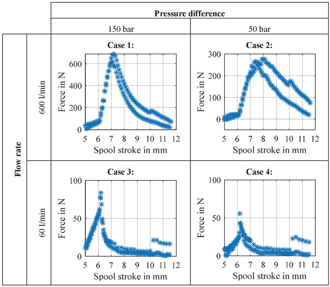
Figure 7 Figure 7 Steady state flow forces of 4/3 directional control valve of nominal size 25 for different operation points.
2.2 Spring and Frictional Forces
Beside the flow forces, the spring forces account for a high percentage of the absolute force value. In Figure 8 the friction and spring forces of the test valve with attached electromechanical actuation unit are shown. For the measurement the valve was driven by the electromechanical actuation unit, without any flow rate applied at port P. In the area of overlap, the step size of the discrete points was increased to 0.5 mm, so that the measuring time could be shortened significantly.
During the measurement the actuator deflects the spool to its maximum stroke and then centers it back in the middle position. Due to the acting friction forces, which superimpose the spring forces, two boundary curves which differ by a hysteresis could be measured. These hysteresis correspond to the sum of the friction forces for the forward and backward movement.

Figure 8 Spring and friction forces of test valve.
For small strokes friction forces of 50 N were measured, which slightly reduce for larger strokes. However, since the acting frictional force depends on the used seal and the applied pressure and since the actuator requires an additional rod seal, the measured friction force is only valid for the used electromechanical actuation system. Pilot operated valves will have lower friction forces since no seal is necessary and other electromechanical actuators may have higher or lower forces depending on the design, the number of sealing points and the used seal. Therefore, this measurement is only suitable for a rough estimation of the acting friction force, which only can be used for a first design of an electromechanical actuation system. Exact determination is usually not possible during the design phase, which is why a large degree of inaccuracy must be accepted for the first design and the actual friction force must be measured under the real operation conditions.
The spring stiffness can be derived from the measurement results shown in Figure 8 by determining the slope across the stroke, which is 20.9 N/mm in the present case. Under the assumption of a similar friction for forward and backward movement the spring force will be located in the middle of both curves. The approximated spring force is drawn as red line in the upper figure. Beside the spring stiffness, the spring’s preload force, which corresponds to the y-axis section of the approximated spring force, can also be derived from the diagram.
In addition to the operation-dependent flow forces, the friction forces of 30–50 N and also spring forces between 250 N and 490 N must be overcome during the switching process. Since the maximum value of the flow forces and the spring force do not occur simultaneously, the maximum occurring force must be identified by superimposing the individual forces. Based on the carried-out measurements a maximum force of 1111 N can be identified at a stroke of 7.2 mm.
2.3 Inertial Forces
The final counteracting force is the inertial force. Its value depends on the spool’s acceleration and mass. Therefore, their value can easily be estimated based on the switching time and the mass. Under the assumption of constant acceleration until the center of the stroke followed by deceleration, an acceleration of 4.8 m/s is necessary for an aspired switching time of 100 ms. Considering a mass of around 1 kg the inertial force can be estimated to 4.8 N, which is considerably smaller than the other forces. Also Kipping has reported, that the inertial forces can be neglected [25].
2.4 Application of Electromechanical Actuators
When aiming to identify advantageous application scenarios for electromechanical actuators each force component must be investigated separately. It must be taken into account that the achievable forces are considerably lower compared to the common pilot operation. Therefore, only operation profiles with small forces are feasible. Depending on the point of operation the flow forces for large sized valves can be up to 700 N and above, which would lead to large and bulky electromechanical actuators, whereas the common hydraulic pilot operation systems are considerably smaller. Operation profiles with low pressure difference, or reduced flow rates will lead to much smaller flow forces and therefore are a promising application scenario for electromechanical actuation systems. Beside the considerably smaller forces, the decisive advantage of electromechanical actuation systems can be fully exploited in these systems. In systems where low pressure levels or even no pressure can be present at the valve’s P-port during the switching moment no internal supply of the pilot valve is possible, and an external pilot circuit is necessary. Therefore, additional costs are incurred for the hydraulic components, the operation of the pilot circuit and the labor required for installation. By the application of an electromechanical actuation unit the pilot circuit can be eliminated and the entire system will be simpler and less expensive. Exemplary systems where the pressure level can drop below the critical value are displacement-controlled systems, in which the pump’s swing angle is reduced before the valve is switched. Correspondingly, there is no flow rate over the valve during switching and therefore also the flow forces are neglectable. Since the variable displacement unit controls the flow rate in these systems, the valve is only demanded to control the flow direction. Therefore, no proportionality is necessary and cheaper directional control valves can be used instead. The electromechanical actuation of large valves is therefore particularly reasonable in the case of directional control valves, which are applied in displacement-controlled systems.
With the aim to reduce the necessary forces further and therefore make the application of common electromechanical actuators possible, the spring forces, which represent the second largest force, were investigated deeper. In common pilot operated 4/3 directional control valves, the springs reset the valve into a centered position. The centering force must be large enough to overcome all counteracting forces at any time [13, 14]. In principle, the springs can be omitted, if the actuation system is capable to take in the middle position actively. Nevertheless, since they fulfil the safety function to close the valve in any safety critical event like power outage, they normally cannot be dispensed with. Through the development of a spring compensated actuation system, the contradiction can be solved. Since the springs are already preloaded in normal operation by the compensation system, the actuator does not have to overcome the spring forces during all movements. It only needs to overcome frictional and inertial forces. This further reduces the necessary actuator force. Therefore, forces below 100 N are required and the application of a common solenoid as electromechanical actuator for large directional control valves is possible. In a safety critical case the relief system is deactivated and the springs centre the spool.
3 Design of Novel Hydraulically Relieved Electromechanical Direct Actuation System for Large Scale Switching Valves
3.1 Principal Design
In Figure 9 the functional structure of a common electromechanical valve actuation system of direct operated valves are depicted. Used are the symbols of elementary functions according to Table 1.
Table 1 Symbols of elementary functions in accordance with
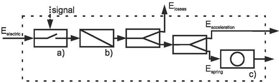
Figure 9 Functional structure of a common electromechanical valve actuation in accordance with [17].
The actuation system consists of a switch (a) and an electromechanical transformator (b), which converts the electric energy E into mechanical energy. Subtracting the losses E due to friction and other resistance forces, the remaining energy is transmitted to the spool and transformed into kinetic energy resulting in an acceleration of the spool. During the movement, a large part of the applied energy is stored in the springs (E), which work as accumulator for mechanical energy (c). This energy is always applied on the spool and the spring force tends to accelerate it in closing direction. Therefore, two mechanical energy paths are leaving the system. If the actuator is deactivated, the stored spring energy will cause the spool to center in middle position. In order to keep the spool deflected, the actuator must thus always apply a greater force to counteract the spring force.
By extending the functional structure by a second branch as shown in Figure 10 the spring relief system can be represented. If the spring is loaded by another actuator, the electromechanical transformator (b) only needs to muster the energy E to overcome the friction and resistance losses and E to accelerate the spool in a sufficient time. This allows not only the downscaling of usable electromechanical actuators, but also the use of previously unsuitable electromechanical transformators.
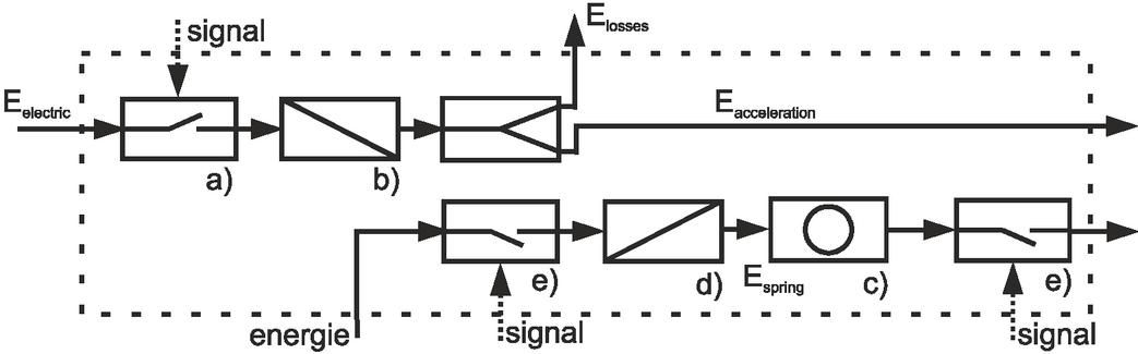
Figure 10 Functional structure of a spring relieved actuation system.
The spring relief system, which is depicted in the lower branch of the functional structure, consist of two switches (e), an energy transformator (d) and the spring (c). The switches (e) serves to control the charging and discharging of the spring c). The spring c) can be charged with an alternative energy supply since the acceleration of the spool and the compression of the spring no longer happen simultaneously.
This concept of divided energy supply was realized in form of a hydraulically relieved electromechanical actuation system, which is displayed in Figures 11 and 12. The actuation system is designed for a 4/3-way directional control valve of nominal size 25, which is implemented in a flow-controlled system. The design is able to apply higher forces than initially required, in order not to be completely limited to the application in displacement controlled system like explained in Section 2. Therefore, the actuator can also switch the valve under certain load.
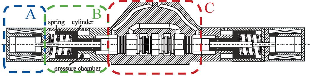
Figure 11 Technical sketch of the novel electromechanical actuation system. Spring relief not active.
The actuation system can be divided into three essential components. The component A represents the solenoid, which translates the electrical energy into mechanical. The hydraulic spring relief system B is located next to the solenoid. It is attached on both sides of the valve’s housing C. To realize an active centering of the spool in neutral position a third solenoid is required, which is not depicted in. The hydraulic spring relief system depicts a spring returned cylinder in B, which centers the spool in case of a power failure. If the pressure chamber is pressurized, the cylinder will compress the spring until reaching the hard stop of the housing. Since the spool and the relief cylinder do not have a mechanically fixed connection, a gap is created between these two components. The spool is floating. This relieved state is shown in Figure 12.
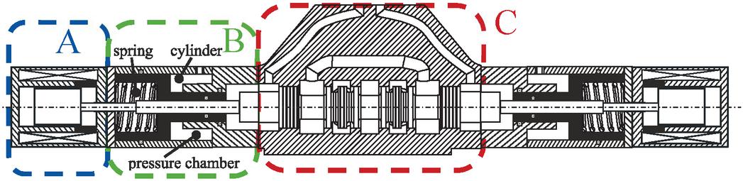
Figure 12 Technical sketch of the novel electromechanical actuation system in hydraulic relieved state.
A rod, which connects the solenoid to the spool, is guided through the relief cylinder to transmit the force mechanically. In case of a power failure, the pressure chambers are relieved against the tank causing the spring to displace the relief cylinder. Thereby the spool also is centered in the middle position.
3.2 CAD of Novel Hydraulically Relieved Electromechanical Direct Actuation System for Large Scale Switching Valves
This new concept for a hydraulically relieved electromechanical direct valve actuation system was designed as a CAD model and was subsequently manufactured. The 3-D Modell is shown in Figure 13. To place the focus on the central aspect of the actuation system, namely the hydraulic relief system, the solenoids are not depicted. A hydraulic spring relief system is attached on each side of the 4/3-way directional valve.
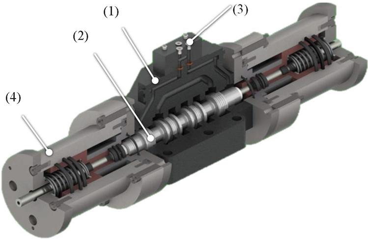
Figure 13 3D-CAD model of the hydraulically relieved actuation system.
The assembly consists of a valve housing (1), a spool (2) an adapter plate (3), which short circuits the pilot chambers to each other with an additional drain line to the tank, and two spring relief systems (4). This assembly is shown in detail in Figure 14. The hydraulic relief chamber (4.1) is formed by the housing (4.2), the relief cylinder (4.3), the spring (4.4) and the force cylinder rod (4.5). The connection port (4.6) represents the system’s connection to the hydraulic system, which will be explained in Section 3.3.
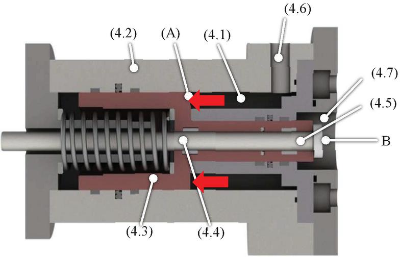
Figure 14 CAD model of the pressure relief system.
Pressure builds up and acts on the area A of the relief cylinder (4.3) during the pressurization of the relief chamber (4.1). If the resulting force is larger than the preload force of the spring (4.4), the relief cylinder will be deflected and the spring will compress. The spool is not centered by the relief cylinder and can be moved freely. If the relief chamber is depressurized, the energy stored in the spring (4.4) will accelerate the relief cylinder (4.3) in closing direction. The stored energy must be sufficient to overcome all resistance forces, like friction or system inherent hydraulic resistance forces and accelerate the relief cylinder (4.3) fast enough to center the spool in sufficient time [13, 14].
During the reset of the process, fluid is displaced through the connection port (4.6) out of the relief chamber (4.1) and drained into the tank. As a result, a pressure difference between the chamber and the tank builds up, which poses a not negligible resistance force. Furthermore, the pressure in the pilot chamber (4.7) is also applied on the surface B, which leads to a further resistance force.
3.3 System Design
The control of the relief system can be realized by two seat valves (1 & 2) arranged in a hydraulic circuit as presented in Figure 15. The control by two seats valves enables the charging and discharging of the relief system as well as the decoupling of the relief circuit from the main circuit. The novel direct electromechanical actuation system is drawn with standardized symbols for hydraulics in accordance with ISO 1219 [26]. The spring relief system can be interpreted as a spring returned cylinder (3), which is mechanically connected through a rod (4) to the spool of the valve. The designed actuation system is driven by three solenoids (5.1–5.3) which are drawn on the bottom line of the valve. The solenoid on the left side can switch the spool to position A, the lower solenoid on the right side to position B and the solenoid above that (5.2) to neutral position.
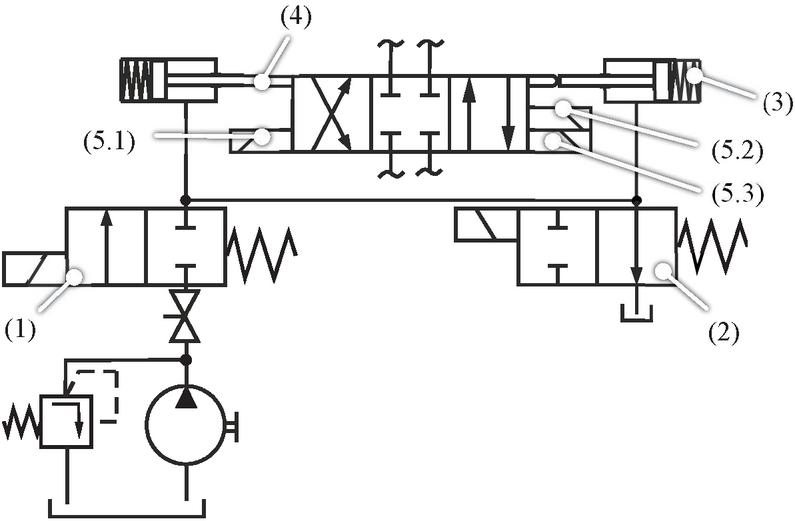
Figure 15 Hydraulic circuit to control the relief system.
The solenoids on the right side are arranged with an offset to each other, so that only when (5.2) is energized the spool takes in the centered position. To fulfil a proper safety function, the loading valve (1) needs to be normal closed (NC) while the unloading valve (2) needs to be normal opened (NO). To activate the relief system the loading (1) and the unloading valve (2) are energized simultaneously. After the system is initialized, the spool is floating and the load valve (1) must be deenergized, so that the relief system is separated from the remaining hydraulic system and only leakage will lead to a pressure change. First measurements have been carried out to demonstrate that the pressure in the relief system does not drop rapidly while active. After the system was fully loaded a ball valve, located between the pump and the loading valve, was closed manually at a time of around 60 seconds. Sequentially the pressure in front of the load valve dropped down to 1 bar. In contrast, the pressure in the relief system could be maintained at nearly the same value for at least two minutes. Exemplary measurement results are displayed over time in Figure 16.

Figure 16 Measurements of the time dependent pressure drop in the designed accumulator.
In case of an electrical power outage, the centered position cannot be attained actively by solenoid (5.2) anymore. The spool will remain in the deflected position requiring the relief system to be deactivated. Due to the operation modes (NC/NO) of the selected loading and unloading valve, this will occur automatically as long as the actuators and the relief system are energized by the same power source. In this case, both the loading and unloading valves will deenergize at the same time, causing the relief chamber to depressurize and therefore the springs to decompress. The spool is thereby accelerated to the neutral position, allowing the valve to take position in its safe state.
When operating in industrial applications, the operation of the relief system must be adapted to the actual system. The simplest possible system design is shown in Figure 17. In this layout, the relief system is supplied by a separate pump. This system design still requires a pilot circuit and therefore possess no significant advantage against common pilot operated systems. If put in contrast to a hydraulic pilot control, the energy required to accelerate the spool and to compress the springs is no longer provided simultaneously. The compression of the springs can be realized before the switching process. Thereby the relief system can be supplied by the main pump without the possible eventuality that the pressure could drop below a critical value. The relief system can be integrated in the main circuit, as shown in Figure 18.
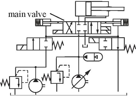
Figure 17 External supply of the relief chamber.
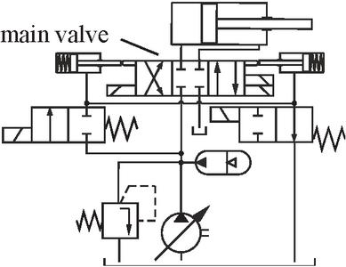
Figure 18 Integrated supply of the relief chamber.
The relief system only can be loaded when pressure in front of the main valve is above a sufficient level. Once the main valve is closed, the delivered flow is relieved by the pressure relief valve directly to the tank. The pressure in the main line then is defined by the systems main pressure relief valve, so that maximum system pressure can be guaranteed. This way the relief system can be loaded by a short swinging movement of the main pump. If necessary, a pressure reducing valve and a second pressure relief valve can be incorporated to prevent impermissibly high pressures in the relief system.
4 Experimental Results
A test rig, according to Figure 19, was built at the ifas lab for experimentally testing of the hydraulically relieved electromechanical direct valve actuation system. The main circuit consists of a servo valve (SV), an adjustable pump (P), a pressure relief valve (PRV) and a directional control valve of nominal size 25 (V), at which the new actuation system has been attached. Additionally, six pressure sensors (p–p), two temperature sensors (T and T) and a flow rate sensor (Q) has been incorporated into the main circuit. Two displacement sensors record the position of the force cylinder rods (4.5 in Figure 14), whereas five current sensors measure the currents of the three solenoids, as well as the loading and unloading valves. Two additional pressure sensors (p and p) have been installed in the relief system circuit. For security reasons and since no burst test could be conducted previously, the power supply of the relief system was realized by an external hydraulic circuit, as shown in Figure 17. After the initial loading of the pressure relief system, its power supply was cut off by a manually operated ball valve. This step was made since beforehand demonstrations showed a reliable holding of pressure over a long period of time in the hydraulic relief system.
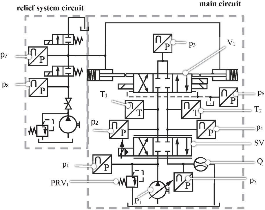
Figure 19 Hydraulic test rig.
Beside the switching and the reset process also the static behavior of the actuation system during high flow phases is interesting, since high flow rates can lead to high flow forces [19, 20, 27]. Aiming to investigate these relevant states of operation two test cycles which can be seen in Figures 20 and 21 have been defined. At the left y-axis the stroke of the actuator is displayed, which corresponds to the relative position of the actuator and its origin state.
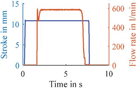
Figure 20 Switching process.
In Figure 20 the test cycle for the investigation of the switching process and the static behavior is depicted. At the beginning of the test cycle the actuation system opens the valve abruptly. Since the servo valve is closed the actuation system always will switch the valve without applied pressure. After a defined time, the servo valve is also opened and a flow rate can pass through the system. As the servo valve is opened rapidly a flow rate peak will occur. This will lead to high static and dynamic flow forces. As can be seen in Figure 20 the actuation system can hold the valve completely open even for flow rates up to 600 l/min. To analyze the reset behavior of the actuation system while different flow rates were passing the valve the second test cycle according to Figure 21 was defined. At the beginning the valve is fully opened, after a defined time the solenoids and the relief system are turned off (t 0 s).
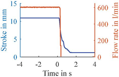
Figure 21 Reset process.
4.1 Switching Process
Switching times of common pilot operated valves are between 40 ms and 250 ms according to datasheets [7, 11]. An aimed switching time of 100 ms was defined for the novel electromechanical valve actuation system to be comparable to common pilot operated valves of nominal size 25. Multiple measurement series with different flow rates were conducted. During a measurement series the test cycle, explained before, was repeated 10 times. The measured stroke and current signal for the measurement series of 0 l/min (Figures 22 and 24) and 600 l/min (Figures 23 and 25) are displayed in the following graphs. The different measurements are shown in different colors.
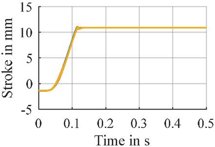
Figure 22 Stroke Signal for measurement series with 0 l/min.
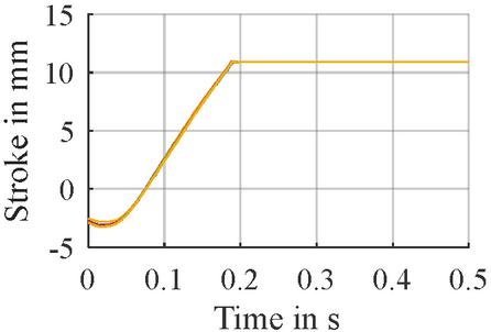
Figure 23 Stroke Signal for measurement series with 600 l/min.

Figure 24 Current signal for measurement series with 0 l/min.
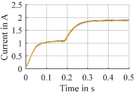
Figure 25 Current signal for measurement series with 600 l/min.
The switching time of the actuation system during the measurement series with 0 l/min is around 130 ms as shown in Figure 15. During the movement the solenoid consumes a current of around 0.85 A. Reaching the end stop the current drops down to 0.75 A due to counter induction. Afterwards the current increased to 2 A. Since the valve switches while the servo valve is in closed position, there is no flow rate passing through the testing valve during the switching process. Therefore, the testing valve should switch under the same conditions, regardless of the flow rate which passing the valve when it is opened. As can be seen in the measurement results, the stroke curves as well as the current curves differ from each other. In the measurement cycle with 600 l/min the switching times increased up to nearly 200 ms. Thereby the solenoid consumes a current of around 1 A and there is no decrease in the current signal like in the measurements with zero flow. Due to these differences, there must be an effect of the high flow rate phase on the system’s conditions during the switching process.
As a pressure is build up at the T port of the valve, a leakage flow over the sealing gap from the tank port to the pilot chamber develops. Therefore the pressure in the pilot chambers also increases. During the measurement cycle with 600 l/min a pressure between 1.5 and 2 bar was measured in the pilot chambers, which could explain the decreased performance by higher sealing friction forces compared to the measurement cycle with zero flow. Whereby the pressure in the pilot chambers was around 0 bar.
4.2 Reset Process
Analyzing the reset times, the solenoids, the loading and unloading valve were deenergized while a flow rate was passing the valve. Again, multiple measurement series were conducted. Each series consists of 10 measurements evaluating the reset times during a given flow rate. The results of the stroke signal are displayed in Figures 26 and 27. The measured pressures at the P and T port (p and p) are displayed in Figures 28 and 29.

Figure 26 Stroke signal of reset process during a flow rate of 50 l/min.
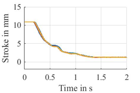
Figure 27 Stroke signal of reset process during a flow rate of 600 l/min.
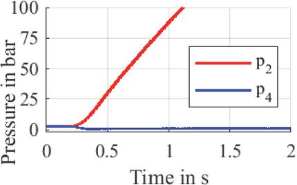
Figure 28 Pressure signal during the reset process with a flow rate of 50 l/min.

Figure 29 Stroke Signal for measurement series with 600 l/min.
As can be seen in Figure 26, the reset time of the relief cylinder and therefore also the cylinder rod during a flow rate of 50 l/min is approximately 750 ms. Due to flow forces acting in closing direction and since there is no mechanical connection between the cylinder rod or the relief cylinder and the spool, the spool can move faster than the relief system. When closing the valve, the opening sectional cross area is reduced, resulting in an increased pressure drop over the valve. Therefore, also the measurement results of the pressure signals p and p are displayed above. The safety-critical moment can be determined from the tank-sided pressure p, at which the valve is completely closed with no pressure downstream of the valve. For both flow rates this point is reached after approximately 300 ms. Considering the positive overlap of the metering edges of 5 mm, pressure p should drop to 0 bar at a stroke of approximately 5 mm. As flow forces are acting in closing direction they support the centering process of the spool and since they increase with small strokes it is likely that the valve spool tends to move faster than the relief cylinder. This can be especially observed in the measurement results of 600 l/min, since the pressure drops to zero bar before the stroke signal reaches a position of 5 mm.
Nevertheless, the relief system is still necessary. Without the relief system, the reset time would only depend on the flow forces. This would present an issue, especially during phases with low flow rates and, since to flow forces are very low for large strokes, as can be seen in Section 2.1. Friction forces may be larger than the flow forces and the spool would stay deflected. As can be seen in Figures 26 and 28 the pressure p drops down to 0 bar nearly by the same time as reaching a 5 mm stroke. In this case, the relief system is primarily responsible for the centering of the spool and therefore the relief system is necessary during low flow rates. And as can been seen in the measurement cycle with a flow rate of 600 l/min (Figures 27 and 29) the closing process is initiated by the relief system and then self-amplifying by the increased flow forces. During the initial 200 ms, both pressures and stroke maintain their initial values. It is only after that time frame that the relief cylinder’s stroke begins to decrease and shortly after the tank-sided pressure also drops. Therefore, it can be concluded that the closing movement is driven by the relief system.
4.3 Switching Under Load
Unlike previous measurements, the servo valve was opened before the test valve, which was thereby pressurized during the switching process. Therefore, the actuation system needed to overcome additional flow forces. The test cycle according to Figure 30 was repeated 10 times. The results of the flow rate (Figure 31), the stroke (Figure 32), the pressures (Figure 33) and the current of the active solenoid (Figure 34) over time are displayed below.

Figure 30 Measurement cycle for switching under pressure.
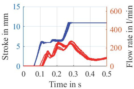
Figure 31 Flow rate with applied 100 bar and 100 l/min.
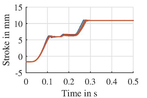
Figure 32 Stroke signal with applied 100 bar and 100 l/min.

Figure 33 Pressure signal with applied 100 bar and 100 l/min.
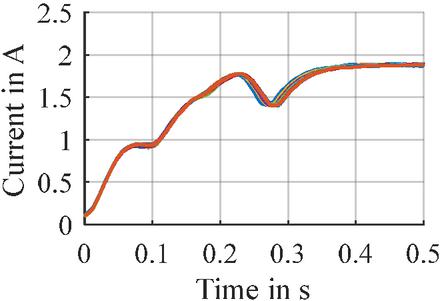
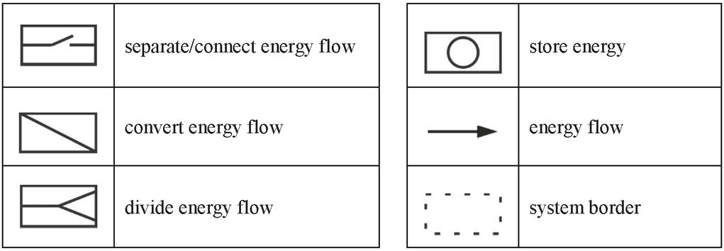
Figure 34 Current signal with applied 100 bar and 100 l/min.
The system was supplied with a flow rate of 100 l/min and a pressure of 100 bar. The valve was operated in a constant pressure system, during which a flow rate peak of 250 l/min occurred. The thereby resulting flow force tends to close the spool. Compared to the stroke signal with no flow rate, a large plateau in Figure 32 can be identified between 0.1 and 0.25 s. During this phase, the force applied by the actuator is in an equilibrium with the flow force. The spool remains in the corresponding position until the flow rate decreases, so the actuation system can overcome the flow force. The gap of the metering edge has only a small opening, as can be seen in the stroke signal (considering the 5 mm positive overlap). At this point of operation, the flow rate is determined by the pressure drop over the valve. Since the occurring flow rate (up to 250 l/min) is larger than the adjusted flow rate of 100 l/min, the pressure before the valve starts dropping (Figure 33) during this operation. As the spool starts moving again, the pressure difference over the valve is reduced to a comparatively low value. The current signal is also significantly increased during the time range of 0.1 to 0.25 s. During this phase, power consumption compared to the previous measurements is increased and therefore higher forces are applied by the actuator. It can be assumed that the solenoid is applying maximum nominal force as the current nearly reaches the nominal value of approximately 2 A. The short-time reduced current demand at 0.28 s is due to the velocity-dependent counter-induction, which occurs when the solenoid armatures reach their end position.
4.4 Evaluation of the Designed Actuation System
The designed concept, which uses solenoid actuators, is able to realize strokes of around 11 mm with switching times of between 130 ms and 200 ms. It can therefore compete with conventional pilot operated valves which achieve switching time between 40 ms and 250 ms. Nevertheless, the designed concept needs further improvement, since the occurrence of internal leakage may affect the actuator’s performance.
With regard to the reset times, the performance of the actuation system is not comparable to common valves, as these achieve considerably shorter reset times. Geometrical optimizations and adapted springs need to be implemented in order to improve the reset time. Even if the designed actuation system reaches reset time of 750 ms, they can still be reduced. It is noteworthy that the flow supported spool is even faster at returning to the middle position, than the relief system in test cycles with high flow rates. A flow supported centring of the spool cannot be guaranteed, and it is necessary to actively initiate the self-amplifying reset process, especially if low flow rates are passing the valve.
Although the concept has previously been adapted to an operation in a flow-controlled system where the pump is completely swung back during the switching process, there are likely only a few existing systems. Therefore, the switching process was also investigated while the valve was pressurized. The actuation system was used to switch the spool while a flow rate of 100 l/min was applied with a maximum pressure of 100 bar. In this case, switching times of approximately 250 ms were achieved. A time interval, during which the stroke signal was constant, suggests no movement of the spool. During that period of time, the acting flow forces in closing direction are in balance with the actuator force. Flow forces at this stage are high, due to the initially occurring flow rate peak. As the pressure before the valve, decreases and the flow rate stabilizes, the flow forces decrease, subsequently allowing the actuator force to accelerate the spool until reaching its full stroke. The application of the actuation system therefore is not limited to flow controlled systems. However, it should be considered that the switching performance and whether the actuation system can switch the valve, depends on the hydraulic system and the operation condition.
As, the relief system was supplied by a separate hydraulic circuit in measurements so far, the integration into a large hydraulic circuit as depicted in Figure 18 should be analyzed in further research.
5 Conclusion
Due to the high counteracting forces valves of large nominal sizes are nowadays usually hydraulically pilot operated. This is an appropriate solution for most applications. However, there are some cases where pilot control has some disadvantages. One example is the actuation of a directional control valve in a displacement-controlled system. In these systems, only insufficient hydraulic power can be provided during the switching moment, which is why an internal supply is not feasible. Therefore, the pilot valve must be supplied externally by a second hydraulic circuit. This means increased costs and effort, which can be reduced by the application of electromechanical actuation systems. In these systems the flow forces in particular are very low since no oil is passing the valve during the switching moment and thus the spring forces represent the greatest resistance force. Therefore, the maximum force is reduced to 44% and the application of electromechanical actuators becomes feasible and advantageous.
In order to further reduce the necessary actuator forces and thus enable the application of low performance class solenoids or electromechanical actuators, a novel hydraulically relieved electromechanical direct actuation system for large scale switching valves was designed. Experiments on the concept show the feasibility. Switching times of around 200 ms and reset times of around 750 ms are achievable. The application of such a concept is particularly useful for systems, in which the main line pressure can drop below a critical value of 4 bar and which inhibits the use of an internally supplied pilot valve. However, the hydraulic spring relief system needs to be controlled hydraulically and thus must be integrated into the main hydraulic system, exemplarily shown in Figure 18. Compared to common pilot operation systems, the dependency between the energy provision to overcome the spring forces and accelerate the spool is resolved. Thus, the main pump can be used to compress the centering springs by supplying the relief system independently from the valve’s switching process. Since the requirements for the actuation forces to shift the spool have been drastically reduced by the relief system, alternative applications of electromechanical actuators are possible.
The concept of a hydraulic spring relief system, which is embedded into an electromechanical valve actuation system, opens up new prospects for actuator implementations. However, the design must be matched to the respective system operation profile. If the application in a constant pressure system is planned, the force of the electromechanical tranformator needs to be adapted to the occurring flow forces.
Acknowledgments
The IGF research project 20084/N of the research association Forschungskuratorium Maschinenbau e. V. – FKM, Lyoner Straße 18, 60528 Frankfurt am Main was supported from the budget of the Federal Ministry of Economic Affairs through the AiF within the scope of a program to support industrial community research and development (IGF) based on a decision of the German Bundestag.
Conflicts of Interest
The authors declare no conflict of interest.
References
[1] G. Bauer, Ölhydraulik: Grundlagen, Bauelemente, Anwendungen: Vieweg Teubner, 2009.
[2] W. Backé and W. Hahmann, Grundlagen der Ölhydraulik: Umdr. zur Vorlesung: Institut für hydraulische und pneumatische Antriebe und Steuerungen der RWTH (IFAS), 1972.
[3] J. Watton, Fundamentals of Fluid Power Control. Cambridge: Cambridge University Press, 2009.
[4] Hydraulic fluid power – Four-port directional control valves – Mounting surfaces, ISO 4401, International Organization for Standardization, Berlin, Jul. 2005.
[5] Hydac International, HYDAC Fluidtechnik: Industrial Valves. [Online]. Available: https://www.google.com/url?sa=t\&rct=j\&q=\&esrc=s\&source=web\&cd=\&ved=2ahUKEwjfwoOrrI\_wAhXZ\_7sIHflED28QFjABegQIAxAD\&url=https\%3A\%2F\%2Findustrialvalves.hydac.com\%2Ffileadmin\%2FIndustrialvalves\%2Fpdf\%2FEN5101-3-02-20\_Industrial-Valves.pdf\&usg=AOvVaw0O4atWlk\_UC\_IwMz5QpAb1 (accessed: Apr. 21 2021).
[6] E. Kauffmann, Hydraulische Steuerungen. Wiesbaden: Vieweg+Teubner Verlag, 1980. [Online]. Available: http://dx.doi.org/10.1007/978-3-322-85723-1
[7] Bosch Rexroth, Directional spool valves, pilot-operated, with hydraulic or electro-hydraulic actuation: type WEH and WH. [Online]. Available: https://www.boschrexroth.com/en/xc/myrexroth/mediadirectory?language=de-DE\&publication=NET\&filterMediatype=1584\&search\_query=24751\&search\_action=submit\&edition\_enum=rd24751 (accessed: Apr. 21 2021).
[8] P. Stump, N. Keller, and A. Vacca, “Energy Management of Low-Pressure Systems Utilizing Pump-Unloading Valve and Accumulator,” Energies, vol. 12, no. 23, p. 4423, 2019, doi: 10.3390/en12234423.
[9] N. Gebhardt and J. Weber, Hydraulik – Fluid-Mechatronik: Grundlagen, Komponenten, Systeme, Messtechnik und virtuelles Engineering: Springer Berlin Heidelberg, 2020.
[10] H. Watter, Hydraulik und Pneumatik: Grundlagen und Übungen – Anwendungen und Simulation: ViewegTeubner Verlag, 2008. Accessed: Jan. 26, 2021.
[11] Parker Hannifin GmbH, Directly operated and pilot operated directional control valves: Series D1VW/D1DW/D3W/D3DW/D31DW/D41VW/D81VW/D91VW. [Online]. Available: https://www.parker.com/Literature/Hydraulic\%20Controls\%20Europe/Manuals\%20UK/DCV1-662\%20UK.pdf (accessed: Apr. 21 2021).
[12] K. Schrank and H. Murrenhoff, “Beschreibung der Strömungskraft in Längsschieberventilen mittel Impulserhaltung,” OP Journal, no. 4, pp. 4–15, 2013.
[13] Helmut Tatar, Störkräfte bei elektromagnetisch betätigte Wegeventilen. Aachen, 1974.
[14] W. Backé and H. Tatar, Untersuchung des Einflusses von Störkräften auf den Schaltvorgang bei Wegeventilen der Hydraulik. Opladen: Westdt. Verl., 1975.
[15] G. Schuster, CFD-gestützte Maßnahmen zur Reduktion von Strömungskraft und Kavitation am Beispiel eines hydraulischen Schaltventils. Aachen: Shaker, 2005.
[16] N. Herakovič, J. Duhovnik, and M. Šimic, “CFD simulation of flow force reduction in hydraulic valves,” Tehnièki vjesnik – Technical Gazette, vol. 22, no. 2, pp. 453–463, 2015, doi: 10.17559/tv-20141128090939.
[17] T. Vonderbank and K. Schmitz, “Design of Electromechanical Actuators for Large Sized Valves,” Proceedings, vol. 64, no. 1, p. 37, 2020, doi: 10.3390/IeCAT2020-08477.
[18] T. Vonderbank and K. Schmitz, “Conceptual Design of Electromechanical Actuation Systems for Large-Sized Directional Control Valves,” Actuators, vol. 10, no. 6, p. 133, 2021, doi: 10.3390/act10060133.
[19] P. Bordovsky, K. Schmitz, and H. Murrenhoff, “CFD Simulation and Measurement of Flow Forces Acting on a Spool Valve,” in 10th International Fluid Power Conference, Dresden, 2016, pp. 473–484.
[20] P. Bordovsky, Evaluation of steady-state flow forces in spool valves: Evaluierung stationärer Strömungskräfte in Schieberventilen, 1st ed. Düren: Shaker Verlag, 2019.
[21] P. Bordovsky and H. Murrenhoff, “Analysis of Flow Angles and Flow Velocities in Spool Valves for the Calculation of Steady-State Flow Forces,” pp. 371–379, doi: 10.3384/ecp17144371.
[22] P. Bordovsky and H. Murrenhoff, “Investigation of steady-state flow forces in spool valves of different geometries and at different oil temperatures with the help of measurements and cfd simulations,” in ASME Symposium on Fluid Power and Motion Control, Bath, 2016.
[23] H. E. Merrit, Hydraulic control systems. New York: Wiley, 1967.
[24] G. Del Vescovo and A. Lippolis, “A review analysis of unsteady forces in hydraulic valves,” in International Journal of Fluid Power, pp. 29–39.
[25] M. Kipping, Experimentelle Untersuchungen und numerische Berechnungen zur Innenströmung in Schieberventilen der Ölhydraulik. Darmstadt: Technische Univ. Darmstadt, 1997. [Online]. Available: https://tubiblio.ulb.tu-darmstadt.de/1263/
[26] ISO, “Fluid power systems and components – Graphic symbols and circuit diagrams: Part 1: Graphic symbols for conventional use and data-processing applications (ISO 1219:2012 Amd.1:2016),” vol. 2012.
[27] N. D. Manring and S. Zhang, “Pressure Transient Flow Forces for Hydraulic Spool Valves,” Journal of Dynamic Systems, Measurement, and Control, vol. 134, no. 3, p. 193, 2012, doi: 10.1115/1.4005506.
Biographies

Tobias Vonderbank received the bachelor of engineering from Hochschule Niederrhein University for Applied Sciences in 2016, and the master of Science from RWTH Aachen University in 2018. He is currently working as Research Associate at Institute for Fluid Power Drives and Systems, RWTH Aachen University. His research areas are Fluid Power, valves and electromechanical valve actuation systems.

Pierre Marc Laßl Chavez acquired the Bachelor of Engineering from the RWTH Aachen University in 2021. He is currently working as a student Assistant in the field of electromechanical valve actuation systems at the Institute for Fluid Power Drives and Systems at RWTH Aachen University.

Katharina Schmitz graduated in mechanical engineering at RWTH Aachen University in 2010 with part of her studies taking place at Carnegie Mellon University in Pittsburgh (USA) and working in Le Havre (France). After graduation, she worked as a scientific staff member and Deputy Chief Engineer at IFAS, the Institute for Fluid Power Drives and Controls of Prof. Murrenhoff. In 2015, Prof. Schmitz graduated as Dr.-Ing. and started working in the industrial sector for a family-owned company, which focuses on special purpose hydraulic solutions and large cylinders. There, she was promoted to Technical Director in 2016. Since March 2018 she is full professor at RWTH Aachen university and Director of ifas, the Institute or Fluid Power Drives and Systems.
International Journal of Fluid Power, Vol. 23_1, 19–52.
doi: 10.13052/ijfp1439-9776.2312
© 2021 River Publishers