Heat Transfer Model of Pneumatic End-Position Cylinder Cushioning
Fedor Nazarov* and Jürgen Weber
TU Dresden, Chair of Fluid-Mechatronic Systems, Germany
E-mail: fedor.nazarov@tu-dresden.de; fluidtronik@mailbox.tu-dresden.de
*Corresponding Author
Received 31 August 2021; Accepted 30 September 2021; Publication 12 November 2021
Abstract
In this paper a thermal model of a pneumatic cylinder with an integrated pneumatic end cushioning is presented. Being a part of a multidomain model presented in former research, this model is needed to simulate and analyse the thermodynamic processes in the pneumatic end cushioning and to elaborate a novel design strategy for damping systems with a higher capability on kinetic energy absorption and robust performance under fluctuating operating conditions. For this purpose, a proper heat exchange model is inevitable to calculate the pressure in the cushioning volume and consequently the deceleration of the load. An approach of splitting the complex geometry of cylinder into simple geometries, such as plain or cylindrical surfaces, is used in this study for a fast computation of convective heat flow rates. To validate this approach, the simulation results were compared with the measurements, carried out at different supply pressures, piston speeds and end cushioning throttle openings. The model will be used further for sensitivity analysis and robust optimisation of the cushioning system design.
Keywords: Pneumatic cylinder, end cushioning, pneumatics, thermocouple, heat transfer.
1 Introduction
Pneumatic drives find a widespread application in the modern industry. They are used as a cheap and reliable alternative to electric drives and as a front runner in some special industrial sectors. Pneumatic applications are essential in food, medical and diverse explosion-hazardous technologies, where they have gained a reputation of hygienic, safe, and reliable systems.
Within the last decades an integration of electronic control systems has made pneumatics smarter, safer, and simpler in both operation and design. However, time-costly manual works are still needed when setting up or adjusting some basic pneumatic components, such as throttles or damping devises. Especially integrated pneumatic end cushioning (EC) is very sensitive to any changes in operating conditions, setup, and environment. To underline this problem, values of four parameters representing the quality of the damping process, travel time , speed in the end cushioning before the stop, peak deceleration , and impact force absorbed by cylinder head , are plotted in Figure 1 A, for a horizontal cylinder drive with pneumatic cushioning. The conductivity of the cushioning throttle is adjusted to decelerate the moving mass at supply pressure , ambient temperature , and meter-out throttle conductance (Figure 1 B) with the lowest shock and within limited travel time of s.
Even a slight deviation of 2 or 5% from the original value of one of these parameters leads to a considerable deterioration of the deceleration. Travel time increases either through an overdamping caused by a too low piston speed in the cushioning region or through an underdamping caused by piston retraction from the cylinder head. Value of piston speed before hitting the cylinder head raises significantly and results in high deceleration and impact force. This leads to unwilled vibrations and noise.
Hence, whenever even one of those five impact parameters has been changed, manual readjustment of the end cushioning throttle is required. The latter has usually a trial-and-error nature and is time-costly. In parallel, a maximum quantity of kinetic energy, absorbed by the end cushioning, often appears as a limitation when sizing a pneumatic cylinder designed to handle heavy objects. An engineer would rather prefer a larger-scaled cylinder with a proportionally higher damping capability to bring the moving mass softly and safely to the end position, even if a smaller cylinder is enough to perform the task. Large-scaling results directly in an increase in energy consumption whilst performing the same net work. For instance, the large scaling is typical for nearly 80% of all applications and avoiding it can contribute to reduction in energy consumption of up to 40% [1].
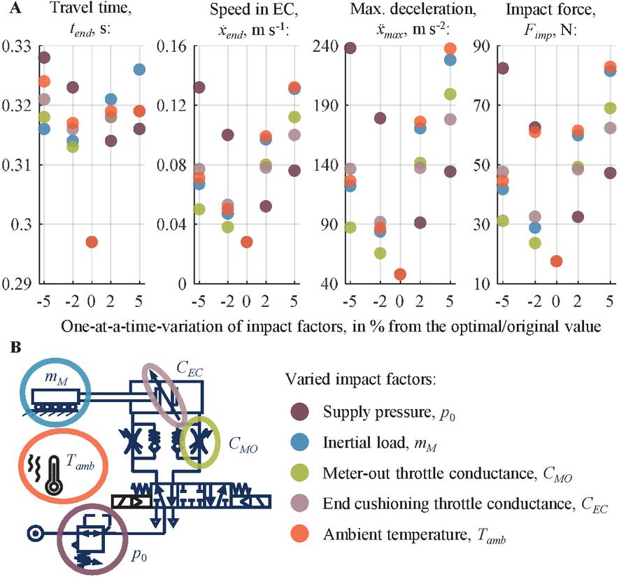
Figure 1 A –Simulated travel time, piston speed before the stop, peak deceleration and impact force values as respond to a one-at-a-time variation of impact factors around the initial value. B – Scheme of the simulated circuit, case: horizontal Ø32-cylinder, stroke 100 mm, inertial mass kg, supply pressure bar.
Besides, low damping force limits the applicability of pneumatic cylinders with an energy efficient meter-in throttle speed control. The reason is a low backpressure level at the end of the stroke. This prohibits the use of the meter-in throttling in the applications, where the advantages of significantly more air-consuming meter-out throttling are not essential.
Having said that, the classical concept of a pneumatic end cushioning needs to be investigated and revised to decrease its sensitivity against the operating conditions and enhance the energy absorption without enlarging the system dimensions or pushing up the costs. The first step towards this global goal is a development and validation of an accurate mathematical model of a pneumatic cylinder with an integrated pneumatic end-position cushioning, which is discussed within this paper. This model is further needed to perform the sensitivity analysis and figure out the design parameters with a highest impact on the damping capability. These parameters, such as cushioning length, cushioning volume in a cylinder head, cushioning throttle conductivity, are accessible for an engineer within a design phase of pneumatic cylinder. Hence, the global goal of the investigation of pneumatic end cushioning is to find the optimal values of these design parameters corresponding to the maximum damping capability and simultaneously to guarantee a high robustness against the fluctuating operating environment, such as volatile supply pressure, alternating mass load or friction force.
This paper focuses only on the development, parameterisation, and validation of a heat exchange model within the pneumatic cushioning. This model should be considered as a part of the model presented in [2], where mainly mechanical and fluid-mechanical domains with an emphasis on friction force and end-cushioning throttle flow parametrisation and simulation are considered, whilst the heat exchange phenomena is only scarcely mentioned. Hence the current paper completes the [2] in terms of multidomain modelling of pneumatic cylinder with an end cushioning.
2 State of the Art
In general, there are different ways to decelerate a moving mass within a limited stroke. Hydraulic shock absorbers possess the highest damping capability and are also widely applied beyond the pneumatic and hydraulic applications. They are reliable in operation and simple in modelling due to only a viscous term and spring force must be considered [3]. However, hydraulic shock absorbers are costly and need to be installed out of the cylinder. This increases the axial dimensions of the drive. A further approach of a non-pneumatic cushioning is external or internal elastic mechanical shock absorber. Such absorbers may have a good damping performance because of sophisticated geometry and materials that guarantee a constant deceleration within a short stroke [4]. However, mechanical dampers usually have a lower damping capability and durability when compared to hydraulic devices and can be applied only within a limited pressure range. External pneumatic damping devices that are free from the drawbacks of the integrated pneumatic cushioning are also present in the market, as for example [5]. Like the hydraulic shock absorbers, they have high acquisition costs and require installation space out of the cylinder.
In this context is obvious, why the integrated pneumatic end cushioning is so widely used in industrial pneumatic cylinders. Their main advantages are low costs, full integration into the cylinder head, reliability, and ease of use. Several studies aimed at mitigation of their drawbacks are devoted to simulation, adjustment, and applicability of pneumatic end cushioning. Wang et al. have developed a mathematical model of pneumatic end cushioning under assumption of an isentropic compression prosses in the end cushioning volume [6]. The simulation of piston speed, deceleration and pressure have shown a good correlation with experiments. In this study the inertial load was varied, whereas the other parameters were kept constant. The authors stated further potentials of model improvement with regards to friction force, fluid damping, leakage, and discharge coefficients of pneumatic ports. Beater has comprehensively studied the damping processes in the pneumatic cushioning as well [7]. For this purpose, a Modelica-based simulation environment PneuLib was used. In this paper, damping capability as a function of the meter-out throttle and cushioning throttle conductances was studied. The author underlines a drawback of pneumatic cushioning in terms of its limited ability to absorb the kinetic energy at the end of the stroke. Especially crucial is a cylinder operation at a high speed. Besides, the cushioning must be readjusted each time the inertial mass is changed. The author also concludes a strategy for a manual adjustment of the cushioning throttle.
Summing up, there are already some mathematical models of the pneumatic end cushioning system existing, as well as some experimental studies are present. Nevertheless, none of them considers a thermal interrelation between the gas and the cylinder body in detail. Friction force model is also simplified or missing. In contrast, the present study aims for a more detailed investigation of the physical phenomena that may have a sufficient impact on the thermodynamic and mechanical parameters, relevant for the further optimisation of the pneumatic cushioning system performance.
3 Mathematical Model
Simulation of physical processes, involved into a deceleration of a cylinder piston, is essential for understanding the interrelations between the domains mechanics, tribology, fluid mechanics and thermodynamics. The mostly used approach for studying and designing pneumatic systems is a lumped parameter modelling, also known as a one-dimensional modelling. The simulation of one-dimensional models is commonly used to investigate the behaviour of components, groups of components and complex pneumatic systems. This approach is used in this study as well. The model is implemented in the software SimulationX by ESI ITI GmbH. In the following sections the model of heat exchange in pneumatic cylinder with an integrated end cushioning is presented and discussed. Detailed modelling of the mechanical, tribological, and fluid-mechanical phenomena are published in [2] and therefore skipped here for the sake of compactness.
A typical example of pneumatic cylinder with an integrated end cushioning is shown in the Figure 2. The functionality of the cushioning device is the same for both rod and base ends (bearing and end caps). Due to a simpler geometry only the base end and therefore only the pull-in (retraction) stroke is considered here. The speed of the piston (travel speed) is assumed to be controlled by a meter-out throttle, which is a common industrial solution.
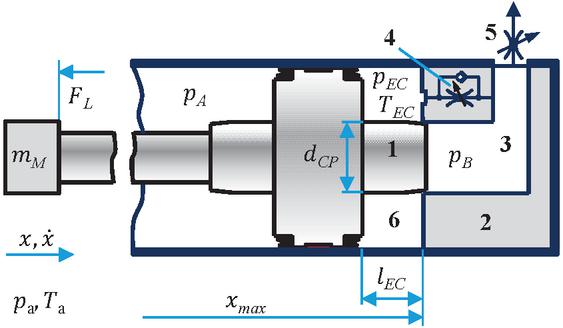
Figure 2 Simplified scheme of a pneumatic cushioning unit: 1 – cushioning plug, 2 – cylinder head, 3 – main outflow channel, 4 – end cushioning throttle (bypass channel), 5 – meter-out throttle, 6 – cushioning volume.
During the main stroke () the left chamber is filled with compressed air at pressure , and the air from the discharges right chamber flows through the main outflow channel 3 and further through the meter-out throttle 5. When the cushioning zone is reached ( or ), the outflow channel is blocked by the cushioning plug 1 and the air can stream only through the bypass with the cushioning throttle 4. Because the conductance of this throttle is significantly lower than that of the outflow channel, the mass flow rate from the discharged chamber decreases while piston still moves toward the base end. As a result, back pressure in the chocked cushioning volume 6 increases and leads to the piston deceleration. The force balance and the thermodynamic model of the air flow during this process are discussed in [2].
3.1 Existing Approaches for Modelling the Heat Exchange
Basically, the complexity of the heat exchange model should be appropriate to the complexity of the studied process. In the simplest case, a pneumatic cylinder can be considered as an isothermal system with an ideal heat exchange with surroundings. This assumption can be applied for example to point-to-point cylinder motion with a cycle time longer than the travel time : . In this case there is enough time for temperature stabilisation between the strokes, and the exact form of the pressure profile, which is inflicted by the temperature, is not of an interest.
To illustrate the typical duration of thermal imbalance between the air and the cylinder wall piston coordinate, temperature, and pressure were exemplary measured during the extension stroke and plotted in the Figure 3. The first temperature peak corresponds to the compression of air that is initially present in the tubes and in the dead volume in the cylinder base end. Since piston starts the movement, more compressed air under the ambient temperature flows into the pressurized chamber, and the temperature of the air mixture decreases. By the end of the stroke a second temperature rise can be observed, caused by a pressure increase up to the value of supply pressure . Its magnitude is usually quite low and the temperature declines to the ambient within about 0.3 s after the end of the stroke.
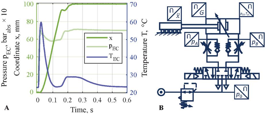
Figure 3 A – Experimental results for extension of horizontal Ø32-cylinder. B – Circuit of the test rig. Temperature is measured with thermocouples Omega CHAL-0005, sensing point for and is marked with asterisks in the Figure 4.
In this context, an isothermal approach is sufficient for some tasks since the heat from the air is completely transferred to the cylinder body shortly after the end of the stroke. This is widely used, for example, to simplify the calculation of an air consumption [8]. However, this is not the case when talking about some energy saving measures as utilisation of the expansion energy in the cylinder chamber [3], servo-pneumatic applications [9] or frequently operated drives [10]. In these cases, neglecting the thermal processes can lead to a considerable error, e. g. when calculating the air consumption or pressure build-up.
The heat can be transported from the compressed air to the environment via natural and forced convection between the pressurized air and inner surface of the cylinder walls, further vie thermal conduction through the cylinder body and finally via natural convection between the outer cylinder surface and environment. The one-dimensional convective heat flow is calculated as
| (1) |
For one-dimensional heat flow via thermal conduction applies:
| (2) |
Here stays for convective heat transfer coefficient, A – surface subject to the heat transfer and orthogonal to the heat flux vector, – thermal conductivity of the cylinder wall material, and – wall thickness. The positive direction of the heat flow rate is assumed to be from the wall to the gas volume, so that the first law of the thermodynamics applies in the from:
| (3) |
that is change in inner energy U equals to the sum of the convective heat flow rate to the gas volume, power applied to the gas volume and the enthalpy flow to the volume through its boundaries. The potential and kinetic energy of the gas are neglected here.
The geometrical parameters and A are usually known, and the conductivity can be assumed as a constant material property because pneumatic applications are seldom subject to high wall temperature changes of 100C. However, the convective heat transfer coefficient may vary considerably and depends on the form of the streamlined surface, temperature, pressure, and gas properties, such as viscosity, density, or thermal conductivity.
There are several approaches for estimating the heat transfer coefficients in pneumatic components. Doll calculated the temperature field of a pneumatic cylinder with Finite Element Method using the constant value of [3]. The simulation results were compared with measurements with a thermal camera for two operation modes. That proves a good quality of the proposed approach respective both temperature magnitudes and distribution. Hepke uses a nearly linear temperature dependence of the heat transfer coefficient since a correlation between the changes in air flow conditions and in temperature can be typically observed in pneumatic systems [10]. The (T)-characteristics used in this study were based on experimental results.
Carneiro underlines the importance of heat transfer consideration when modelling servo-pneumatic systems and proposes a handy method for experimental estimation of thermal transmittance of pneumatic cylinders [9]. A comprehensive approach of heat transfer coefficient calculation is proposed by De Giorgi for pneumatic reservoirs [11]. The coefficient for natural and forced convection is estimated basing on the dimensionless similarity numbers Gr, Pr, and Re.
3.2 Heat Exchange Model of Cylinder with Pneumatic end Cushioning
The above-mentioned methods are applicable if the cylinder can be treated as a system consisting of only two main chambers divided by the moving piston. In contrast to this usual architecture the third, cushioning volume, is unavoidable when modelling the end cushioning. This volume appears only within the cushioning zone ( or , according to Figure 2). The geometrical form of the cushioning volume is more complex than that of the cylindrical main chamber and there are more surfaces involved in heat exchange than only inner cylinder wall.
For this reason, in this paper an approach proposed by Michel for modelling the thermal processes in compact electro-hydraulic drives is transferred into pneumatic application [12]. The components of the cylinder assemblage (base end, cylinder body, piston, rod, rod end) are treated as cylindrical bodies with simplified surfaces on which the heat exchange is expected to be non-negligible. Figure 4 shows these surfaces for the base end cap and a segment of a cylinder body and a piston.
Each of the coloured surfaces plays a role in the heat transfer between the compressed air and the cylinder body. To obtain the heat transfer coefficient for each of these surfaces, the Rayleigh and Prandtl numbers for the natural convection and Reynolds and Prandtl numbers for the forced convection are calculated firstly. Then the Nusselt number can be estimated using empirical equations specific for each geometrical form of the surface, flow conditions and convection type [13]. The properties of the surfaces 1–11 from the Figure 4 are listed in the Table 1.
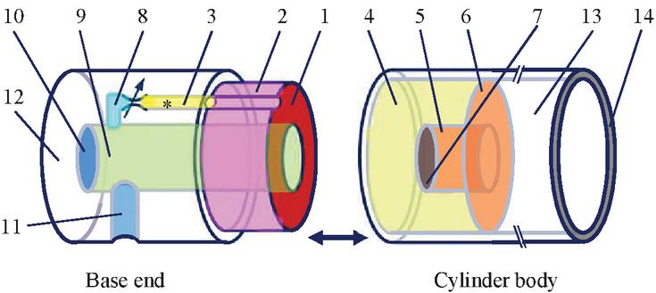
Figure 4 Geometry simplification of the base end and fragment of piston and cylinder body. Asterisks (*) marks the sensing point for and during experiments. The surfaces are listed in the Table 1.
Table 1 Pr operties of the simplified surfaces involved in the heat exchange when considering the cushioning volume: 1-11 – combined convection, 12 and 13 – natural convection, 14 – joint heat transfer
| Surface Subject to | Surface | Flow Direction Relative | Heat |
| the Heat Transfer | Form | to the Surface | Flux Receiver |
| 1 – centering plug front side | flat plane | orthogonal | base end |
| 2 – centering plug | cylinder | parallel | base end |
| 3 – EC-throttle channel 1 | cylinder | parallel | base end |
| 4 – cylinder inner surface | cylinder | parallel | cylinder body |
| 5 – EC plug | cylinder | parallel | piston |
| 6 – piston front side | flat plane | orthogonal | piston |
| 7 – EC plug front side | flat plane | orthogonal | piston |
| 8 – EC-throttle channel 2 | cylinder | parallel | base end |
| 9 – outflow channel | cylinder | parallel | base end |
| 10 – outflow channel front side | flat plane | orthogonal | base end |
| 11 – fitting bore | cylinder | parallel | base end |
| 12 – base end outer surface | cylinder | – | base end |
| 13 – cylinder outer surface | cylinder | – | cylinder body |
| 14 – cylinder body front side | flat plane | – | cylinder body & base end |
Finally, the heat transfer coefficient is estimated using the Nusselt-number:
| (4) |
where l is a geometrical parameter characterizing the surface and is thermal conductivity of air at current pressure and temperature.
The negative heat flow rate calculated with Equations (1) and (4) from the hot compressed air to each of the surfaces at initially ambient temperature, decreases the inner energy of the gas volume as stated in (3). The heat flow rate taken from a gas volume is the sum of the heat flow rates absorbed by the cylinder walls that enclose this volume:
| (5) |
where , for heat flow rate from the air in the end cushioning volume to the cylinder base, piston and cylinder body, and , for heat flow from the dead volume to the cylinder base. The indices i are associated with the surface enumeration from the Figure 4 and Table 1.
To compare the simulation and experimental results and to assess the model quality by this comparison, the coefficient is introduced to fit the discrepancy between the simulation and the measurement. The reasons for this expected difference between the calculated and real heat flow rate are inhomogeneous velocity and temperature profiles of the real air flow in the cylinder and the dynamic behaviour of the thermocouples used for the temperature measurement.
| (6) |
The heat conducted through the cylinder wall to the outer surface is absorbed by an atmospheric air by means of natural convection. In the example considered in the Figure 4 only surfaces 12 and 13 are involved in this process. The heat diffusion between separate parts of the cylinder assemblage, e.g. between the cylinder body and base end, is considered as joint heat transfer. The radiative heat flow was neglected in this study since the temperature difference between the outer cylinder surface and the environment was assessed as very low (1C) within the one stroke studied.
3.3 Temperature Measurement
To validate the model of pneumatic end cushioning, static pressure and temperature in the cushioning volume, and piston coordinate x were measured. The sensing point for both temperature and pressure is marked with asterisks (*) in the Figure 4. For temperature measurements a thin K-type thermocouple Omega CHAL-0005 was used. It has a bare sensor head with diameter of only 12.5 m. Low thickness results in a low heat capacity of the sensor head and consequently in a short response time. Unfortunately, no exact data about the response time of this model can be obtained from the datasheets. Besides, the heat transfer from the air to the sensor head via convection depends on pressure, temperature and flow velocity. Thus, the time constant may be defined only for one operating point, whereas the air parameters in the cushioning channel vary significantly. To estimate at least a rough value of the time constant, a simple test rig was assembled to expose the sensor head to a temperature change with an amplitude of C within a short time of about ms at upstream velocity of 5 m s. The measurement results and scheme of the test circuit are shown in the Figure 5.
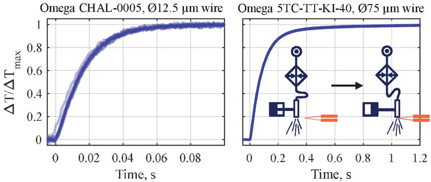
Figure 5 The overlapped results of 10 response time measurements for each of Omega fine-wire thermocouples and the scheme of the test circuit.
From these exponential response plots the time constant of sensor CHAL-0005 of 16 ms was determined. That means, the sensors head is expected to be heated or cooled down up to the real air temperature within about 80 ms at the given flow velocity. The reaction time of the signal amplifier amounts 0.5 ms and is therefore negligible when considering the entire measuring circuit. Using this time constant in the model, a signal from the thermocouple can be simulated as a PT1-element and its output is expected to be comparable with the measured temperature. The data were acquired with an oscilloscope.
Besides the thermocouple CHAL-0005 was compared with Omega 5TC-TT-KI-40-1M, used by other authors for temperature measurements in pneumatic systems [10, 14]. Its time constant was measured by 92 ms and a reaction time amounts ca. 460 ms.
4 Results and Discussions
The measurements results for supply pressures bar and bar, full meter-out throttle opening (maximum speed) and three openings of the end-cushioning throttle knob , corresponding to its different pneumatic conductances and hence various damping intensity, are shown in the Figures 6 and 7. The test rig is presented in the Figure 3, B.
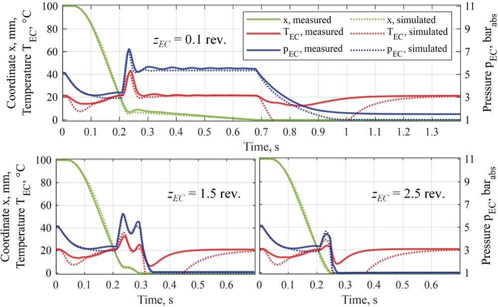
Figure 6 Piston stroke x (green), cushioning temperature (red) and pressure (blue) measured for different openings of the end cushioning throttle at bar and moving mass kg.
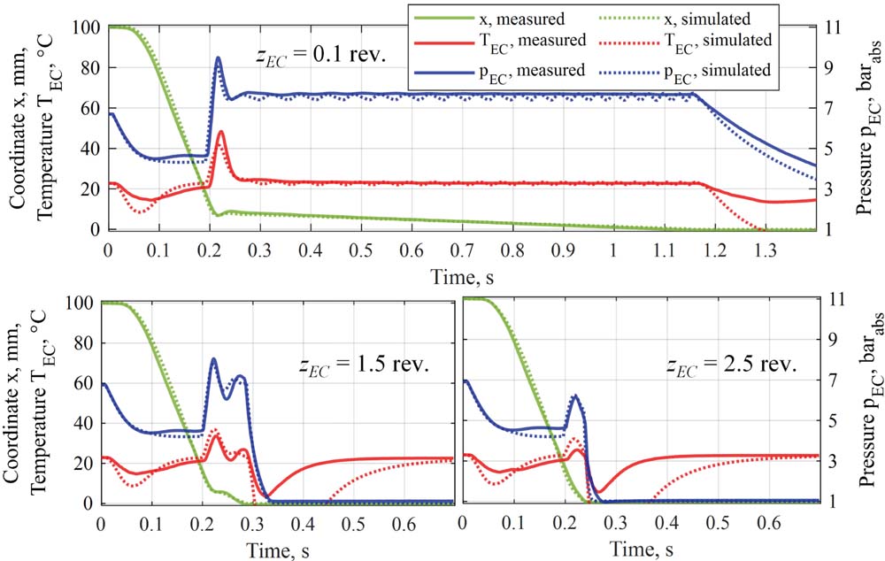
Figure 7 Piston stroke x (green), cushioning temperature (red) and pressure (blue) measured for different openings of the end cushioning throttle at bar and moving mass kg.
Here the simulated temperature was fitted to the measured temperature profile with a heat flow rate proportionality coefficient . That means, that the convective heat flow rate, computed with the proposed approach of splitting the complex cylinder geometry into simple geometries, calculating analytically separate heat transfer coefficients and separate heat flow rates for these geometries, and then adding them back together, is ten times smaller than that can be concluded from the measurements. This difference appears to be significant, however it should be noted that because of a high dynamic of the cushioning process the real temperature profile does not correspond exactly to the temperatures, measured with the CHAL-0005 thermocouple. As mentioned above, the time constant of the thermocouple was kept constant in the simulation model, whereas it depends significantly on pressure and flow velocity. From the datasheets for the other thermocouples of Omega with a wire diameter from Ø0.03 to 0.81 mm can be obtained, that their time constant differs by factor 12.5 when measuring the temperature in the stationary air and in the air flow with speed of 18 m s [15]. That leads to a conclusion that even the measurements with 12.5-m-thin sensors should be discussed critically when talking about high-dynamic temperature changes. This also can explain the good correspondence of the temperature profiles during the movement, and especially in the cushioning region, and worse correspondence after the piston stops and no flow is present.
On the other way around, geometry simplification and assumption of the homogeneous flow and temperature profile along the streamlined surfaces in the proposed heat transfer model also contributes to the difference between simulated and measured values.
An indirect but important criterion for quality assessment of the proposed heat transfer model is pressure. Pressure is coupled with temperature and its profiles match accurately for all measurements during the piston movement. The simulation model with estimated constant fitting coefficient delivers results that correspond well with the experiments, especially in the end cushioning region, which is essential for the study purpose. Summing up, the model can be used to predict the cushioning behaviour, analyse the cushioning system, and carry out its numerical optimisation.
5 Summary and Outlook
The conductance of the end cushioning throttle is usually the only once parameter that the user can adjust to reach the desirable damping quality and time, when taking a pneumatic drive into operation or maintaining it. The quality of the cushioning process can be quantified with an integral criterion that takes into account cushioning time, peak deceleration, and the maximum capability on energy absorption. This quality is not equal for the same throttle opening when operating the cylinder drive under various supply pressures, travel speeds and inertial loads. Hence, the global aim of the analysis of integrated pneumatic end cushioning is to figure out, how the geometry of the cushioning throttle and the cylinder can be designed to guarantee a fast and repeatable deceleration and to minimize the sensitivity against fluctuating operation parameters, such as pressure, moving mass, and friction and load forces. This problem can be solved by the multiparametric robust optimisation of the end cushioning.
For this purpose, a one-dimensional simulation model of the pneumatic cylinder with an integrated pneumatic cushioning system was developed. The mechanical and fluid-mechanical part of the model are presented in the former study [2], whilst this paper addresses the heat transfer part of the model needed to obtain the pressure values during the cushioning stroke and hence the deceleration. The simulated piston stroke, pressure and temperature in the end cushioning volume are experimentally validated. The comparison plots, presented in the Figures 6 and 7, show consistency of the stroke, pressure and temperature profiles, although for the latter convective heat flow rate needed to be increased by factor 10. This was explained with an inhomogeneity of the real flow and temperature profiles in the cylinder and the less-known dynamic behaviour of the thermocouples used in the experiment.
Summing up, the proposed approach represents a compromise between a low simulation time and sophistication level. This level can be increased by coupling the present one-dimensional model with a two- or three-dimensional model solved with finite element or finite volumes method but would increase the computation time significantly. Simulation time is essentially important for sensitivity analysis and robust optimisation because it may require up to 100,000 model runs. Thus, the designed one-dimensional model with simulation time varying between some tenths of the second up to few seconds is proper for the following optimisation and has an acceptable level of representativeness of the real matter.
Acknowledgement
This research is funded by the European Social Fund and co-financed by tax funds based on the budget approved by the members of the Saxon State Parliament.
References
[1] EnEffAH Energy efficiency in production in the drive and handling technology field: Basic principles and measures. EnEffAH Project Consortium, Stuttgart, 2012. Last access on August 31st, 2021: https://www.eneffah.de/EnEffAH\_Broschuere\_engl.pdf.
[2] F. Nazarov, J. Weber, ‘Modelling, Simulation and Validation of the Pneumatic End-Position Cylinder Cushioning’, Proc. of 17th SICFP, pp. 248–265, Linköping, Sweden, May–June 2021.
[3] M. Doll. ‘Optimierungsbasierte Strategien zur Steigerung der Energieeffizienz pneumatischer Antriebe’, dissertation, Shaker Verlag, Aachen, 2016.
[4] ACE, NoCushion Serie. ‘Externe Endlagendämpfung für Pneumatikzylinder’, White Paper.
[5] AIRTEC, ‘InnoMotix-System. Pneumatik ohne Dämpfer’, White Paper.
[6] Y. T. Wang et al., ‘Computer Simulation of a Shock-Absorbing Pneumatic Cylinder’, Journal of Sound and Vibration, 93 (3), pp. 353–364, 1984.
[7] P. Beater, ‘Endlagendämpfung pneumatischer Zylinder’, OP Ölhydraulik und Pneumatik, 47 (2003), No. 3: pp. 163–167, 2003.
[8] J. Hepke, J. Weber, ‘Energy saving measures on pneumatic drive systems’, Proc. of 13th SICFP, pp. 475–483, Linköping, Sweden, June 2013.
[9] J. F. Carneiro, F. Gomes de Almeida, ‘Heat transfer evaluation of industrial pneumatic cylinders’, Proceedings IMechE, Part I: J. Systems and Control Engineering, Vol. 221, pp. 119–128, 2007.
[10] J. Hepke, ‘Energetische Untersuchung und Verbesserung der Antriebstechnik pneumatischer Handhabungssysteme’, Dissertation, Shaker Verlag, Aachen, 2017.
[11] R. De Giorgi et al., ‘Dynamic thermal model of a discharging process of a pneumatic chamber’, Proceedings of 4th FPNI-PhD Symposium, Sarasota, pp. 571–583, 2006.
[12] S. Michel, J. Weber, ‘Thermischer Haushalt und Verschleiß elektrohydraulischer Kompaktantriebe’, Final Report, IGF Proposal No. 18051BR, TU Dresden, 2016.
[13] VDI-Gesellschaft Verfahrenstechnik und Chemieingenieurwesen (GVC), ‘VDI-Wärmeatlas’, 11. Ausgabe, Springe-Verlag Berlin Heidelberg, 2013.
[14] J. M. Hassan et al., ‘Experimental investigation of a temperature change inside pneumatic cylinder chambers’, Al-Nahrain Journal for Engineering Sciences (NJES), Vol. 20, No. 1, pp. 1–4, 2017.
[15] OMEGA, ‘Unisolierte Feindraht-Thermoelemente aus Wolfram/Rhenium, Platin/Rhodium und Standardlegierungen’, White Paper.
Biographies

Fedor Nazarov received the bachelor’s and master’s degrees in hydraulic, pneumatic, and vacuum systems engineering from South Ural State University in 2014 and 2016 respectively. Since 2017 to this day, he is working as a Research Assistant at the Chair of Fluid-Mechatronic Systems, TU Dresden. His research areas include simulation and optimisation of pneumatic systems and components with regards to energy efficiency and performance.

Jürgen Weber has been appointed university professor and chair of Fluid-Mechatronic System Technology at the TU Dresden. Since July 1st, 2018, he is the director of the Institute of Mechatronic Engineering. Prior to this, for approximately 13 years, he has been active in various positions at the R&D department of the agricultural and construction machinery manufacturer CNH.
International Journal of Fluid Power, Vol. 23_1, 1–18.
doi: 10.13052/ijfp1439-9776.2311
© 2021 River Publishers