Analysis of Self-oscillating Single-acting Hydro-impact System Operational Modes with Two Limiters of Striker Movement
Leonid V. Gorodilov
N.A. Chinakal Institute of Mining, Siberian Branch, Russian Academy of Sciences, Krasnyi pr. 54, Novosibirsk, 630091 Russia
E-mail: gor@misd.ru
Received 28 July 2019; Accepted 22 August 2019; Publication 20 November 2019
Abstract
A new property of self-oscillating single-acting hydro-impact systems is considered in this paper – an ability to make strikes in forward and backward directions in presence of two limiters of striker movement without structural changes in device. Mathematical models are presented for system, which includes a flow rate source, a control valve, an impact unit (body frame, striker and spring), an energy accumulator and two limiters. Program for system operational modes (op-modes) simulation is developed and dynamics of specific typical device is numerically investigated. Theoretical oscillograms of its dynamic characteristics and dependencies of integral characteristics on source and impact device parameters are analyzed. At low flow rate multi-impact self-oscillating cycles are obtained, in which the nature of dynamics phenomenon repeats after several striker-limiters interactions. Increase of flow rate leads to single-impact working mode with forward direction of striker movement, then to transition to double-impact mode with forward and backward directions and, further, to single-impact mode with backward direction. Transition boundary points, in which system op-modes changes, are found. Results of this paper can be applied in development of reversible hydro-impact devices (with impacts in forward and backward directions) for mining and construction engineering.
Keywords: hydro-impact system, reversing mode, strike power.
1 Introduction
As well known, equipment jamming during wells boring or other borehole technological operations is one of the problems that often occur. Especially, it can happen in fractured rocks, for instance, in coal layers during borehole degassing (Lekontsev and Sazhin, 2014). Boring equipment blocking can occur due to insufficient cleaning of wells from drilled cuttings (Manzhosov and Novikov, 2015). This leads to equipment deterioration and well failure, which significantly increases cost of work.
An effective solution can be found in the development of special impact devices, the striker of which makes a reciprocating motion with strikes on the limiter. The limiter is the case of the jamming equipment. The impact load applied to the case allows to overcome the jamming effect and release the equipment.
Hydro-impact devices, which are used in industry, are designed to produce impact load in single direction. The study of hydro-impact device dynamics and general characteristics can be found in the following works: Alimov and Basov, 1990; Gorodilov, 2010; Gorodilov, 2018; Gorodilov, Vagin and Rasputina, 2017; Ficarella, Giuffrida and Laforgia, 2006; Giuffrida and Laforgia, 2005; Franco and Ferraresi, 2017.
However, single direction hydro-impact devices may not be effective at eliminating jamming in the well. Therefore, it may be necessary to overcome this negative effect utilizing a forward and backward acting hydro-impact device.
We have found that self-oscillating single-action hydro-impact systems designed with second limiter of striker movement, become reversible, i.e. receive the ability to produce impacts in forward and backward directions without structural changes in the device. When removing one of the limiters, one can obtain single-impact system of either forward or backward action (Alimov and Basov, 1990; Melamed et al., 2000; Gorodilov, 2010).
This paper presents the results of numerical investigations of single-acting hydro-impact system with two limiters of striker movement. The influence of flow rate supplied to the impact device on its op-modes and characteristics is analyzed. The influence of striker position change, in which device’s hydraulic chamber connects to pressure line, on impact power is presented.
2 General Schemes of Mass Movement Under Action of Alternating Force with One or Two Limiters
As a rule, in the study of general properties of hydro-impact systems, including single-acting, calculation scheme (Figure 1(a)) is used, in which mass movement m (of the striker) is limited from one side by limiter L1 (Alimov and Basov, 1990; Gorodilov, 2010; Babitsky, 2013). Diagram of sign and traversal direction of force F, acting on the striker during working cycle, is shown in Figure 1(b).
The dynamics of mass can be described by a system of differential equations (Alimov and Basov, 1990; Babitsky, 2013)
| (1) |
with initial data
| (2) |
with additional conditions at fitting points
| (3) |
where x, v and t are striker coordinate, velocity and time, respectively; −x1 and −x2 are coordinates of force sign change; R is coefficient of restitution of striker velocity, v- and v+ are striker velocity before and after impact.
Solution of system (1)–(3) in case with source of constant pressure (force F is piecewise constant) can be obtained analytically (see, e.g., (Alimov and Basov, 1990; Babitsky, 2013; Gorodilov, 2005)), in case with source of constant flow rate (force F is variable) – only numerically (Gorodilov, 2012, 2018).
Second limiter of striker movement L2 (Figure 2(a)) is included in calculation scheme of reversible system, diagrams of signs of applied forces may present one of the shown in Figure 2(b)–(d) types. Additional conditions at fitting points are the following:
| (4) |
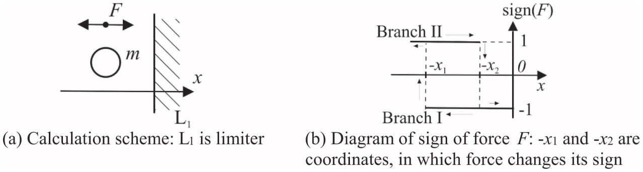
Figure 1 Calculation scheme and diagram of signs of force F, applied on mass m with one limiter.
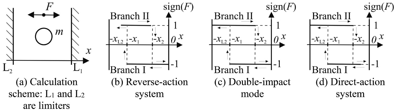
Figure 2 Calculation scheme and diagrams of signs of force F, applied on mass m with two limiters.
Note, that in case of single-acting system, hydraulic force acts on striker during only one of the cycle phases (for reverse-action system – this is a phase of backward strike corresponding to branch I (Figure 2(b)–(d))), during phases of stopping-down and forward movement (to coordinate −x2) hydraulic force is equal to zero. Herewith, movements occur under elastic force action between the body frame and the striker of impact unit, which value is determined by their mutual position.
Consider mathematical models of single-acting impact system with calculation schemes for source of constant pressure and source of constant flow rate. Elastic connection between the body frame and the striker is considered as linear.
3 System with a Source of Constant Pressure
System (Figure 3) includes a source of constant pressure E with pressure pn, tank T, an on-off control valve V, an impact unit (built-in body frame C and piston-striker P of mass m and SA – area from the side of chamber A), a spring S of stiffness cm, which connects body frame, striker and limiters L1 and L2 of striker movement. Hydraulic resistance and mechanical friction losses can be neglected.
Control valve V has feedback of striker position P: when it passes coordinates −x1 and −x2, it changes position from I to II and back. Position V determines the sign of force acting on the striker, as shown in diagram of Figure 2. It is considered that the control valve changes regimes instantly and does not produce losses in the system.

Figure 3 Design scheme of hydro-impact system with a source of constant pressure: E is source of constant pressure with pressure pn, T is tank, V is valve, C is body frame, P is piston-striker, S is spring, U is valve control line, L1 and L2 are striker movement limiters.
The presented system works as follows. At initial moment valve is in position I, striker P – near L1 limiter, valve control line U is connected with the drain line through a striker groove, chamber A of impact unit – with pressure line. When sourse E is activated and fluid is supplied on pressure line, striker P moves to the left under the influence of the hydraulic pressure in chamber A and forces from spring S, reaches coordinate −x2 (U disconnects from drain line), then – coordinate −x1 (U connects with pressure line). Valve passes into position II under the hydraulic pressure in the control line U. Chamber A connects with drain line, striker P movement occurs only from elastic force influence of spring S. In this phase, striker slows down its speed and can hit limiter L2. After stopping, striker P moves to the right and accelerates. When it passes coordinates −x1 and −x2, valve control line U disconnects from pressure line and connects with drain line. The valve returns to position I, chamber A connects with pressure line. Striker slows down and can hit limiter L1. After stopping, it starts moving to the left, cycle repeats.
Striker movement is described by differential equations
| (5) |
where S(J) = SA, if valve is in position I, S(J) = 0, if valve is in position II, with initial conditions (2) and additional conditions at fitting points (4).
4 System with a Source of Constant Flow Rate
In comparison with previous system, in design scheme (Figure 4) source of constant pressure is replaced by source of constant flow rate with flow rate q0, nominal pressure pn and efficiency η0. In this case, efficiency takes into account general leaks, determined by resistance r0 = pn/q0(1 − η0). A spring type hydraulic accumulator M is added in this system with a spring stiffness, cM and piston area, SM. The spring and piston masses are neglected.

Figure 4 Design scheme of hydro-impact system with a source of constant flow rate: F is source of constant flow rate, T, V, C, P, S, L1 and L2 are same as in Figure 3, M is accumulator, q0 is flow rate, r0 is hydraulic resistance, taking into account system leakages.
The same assumptions about the hydraulic and mechanical losses that were made in the previous scheme are considered in the constant flow scheme. Its working cycle also proceeds in the same way.
Striker and accumulator dynamics is described by differential equations (Gorodilov, 2005):
| (6) |
( is spring-controlled accumulator capacity, p/r0 is system leakages under pressure p), with initial conditions (2) and additional conditions at fitting points (4).
5 Numerical Study of Dynamics and Integral Characteristics of Hydro-impact System with Two Limiters
Equations (2), (4), (6) were integrated numerically by the Runge – Kutta method with Egorov control member (Arushunyan and Zaleytcin, 1990). In purpose to adjust solutions at conjunction points, fitting method was used (Besekerskii and Popov, 2004). Calculations were carried out until system comes up to limit self-oscillatory cycle, which can be determined by the following conditions
where , – velocities of striker in moment of valve moving from I to II positions of, respectively, i-th and i–1-th cycles (in case of multi-impact cycles in next cycle we assumed first oscillation with impact), ɛ = 10−6 is local accuracy.
Calculations are carried out for the following system parameters:
| – striker mass m | 6 kg |
| – striker area from the side of chamber A SA | 4.5 · 10−4m2 |
| – coordinates x1 and x2 | 0.05 and 0.03 m |
| – distance between limiters xL2 = |L1L2| | 0.08 m |
| – spring stiffness cm and preload deformation x3 | 3 · 104 N/m and 0.05 m |
| – striker velocity coefficient of restitution R | 0 |
5.1 Simulation with a Source of Constant Flow Rate
Suppose the following parameters of the source: nominal pressure pn = 14 MPa, efficiency η0 = 0.7. Let us change the flow rate q0 from 5 · 10−5 to 5 · 10−4m3/s. Spring stiffness and accumulator piston area are cM = 3 · 104 N/m and SM = 12 · 10−4m2, respectively.
Qualitative theoretical oscillograms of system’s limit cycles, obtained under conditions of giving parameters and varying flow rate q0, are shown on Figure 5.
Their analysis allows to allocate several types of self-oscillating limit cycles of the system under consideration: (1) multi-shock mode (Figure 5(a)) at a flow rate up to 1.7 · 10−4m3/s with impacts in the forward direction; (2) single-impact mode (Figure 5(b)) at a flow rate of 1.8 · 10−4 to 2 · 10−4m3/s with impacts in the forward direction; (3) double-impact mode (Figure 5(c)) with impacts in forward and backward directions at a flow rate of 2 · 10−4m3/s to 2.7 · 10−4m3/s and (4) single-impact mode with impacts in the backward direction (Figure 5(d)) at a flow rate higher than 2.8 · 10−4m3/s.
At low flow rate average pressure in considered system in limit cycle can be decreased from one oscillation to next (Figure 5(a)). While during the next oscillatory motion, the pressure is insufficient for the striker to overcome spring elastic forces and reach coordinate −x1. At a certain moment, force, acting on striker from the side of spring, when moving from limiter, turns out to be higher than force of liquid, striker slows down and stops before reaching coordinate −x1, then oscillates in opposite direction, leading to pressure increase in chamber A. Striker returns, passes coordinate −x1 and, after chamber A disconnects from pressure line, making forward movement resulting in strike about limiter. In some cases, striker can perform more than one oscillatory motion to reach coordinate −x1.
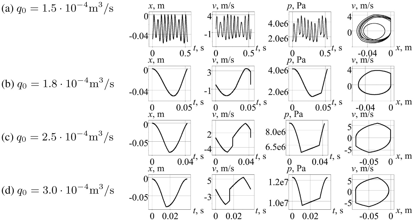
Figure 5 Theoretical oscillograms of dynamic characteristics (striker coordinates x and velocity v, pressure p in system) and velocity phase curves of system with two limiters under varying flow rate q0.
Transition to single-impact limit cycle occurs due to flow rate increase (Figure 5(b)). Pressure level in system rises up to value required to overcome spring reaction forces at each striker movement to coordinate −x1.
Further flow rate increase leads to the fact that striker is accelerated by liquid pressure while moving to the left, overcomes spring force by its own inertia and moves until it hits limiter L2 – coordinate −xL2. While moving to the right, after passing coordinate −x2, there is not enough liquid pressure to provide sufficient reaction and stop striker before coordinate 0. Striker again hits limiter L1 and system turns out to double-impact mode.
Now, transition to single-impact mode occurs due to increase of flow rate to level at which pressure in system increases so that, while passing coordinate −x2 and after chamber A connects with pressure line, striker can’t overcome hydraulic force acting on it, slows down and stops without hitting limiter L1. At this time, striker hits limiter L2.
Dependencies of pre-impact velocities vI upon striker interaction with right and left limiters, impact frequency f and average accumulator pressure pm on flow rate q0 supplied to device are shown on Figure 6. Since several modes are observed, then in the case of multi-impact mode pre-impact speed vI and frequency f were estimated by their average values.
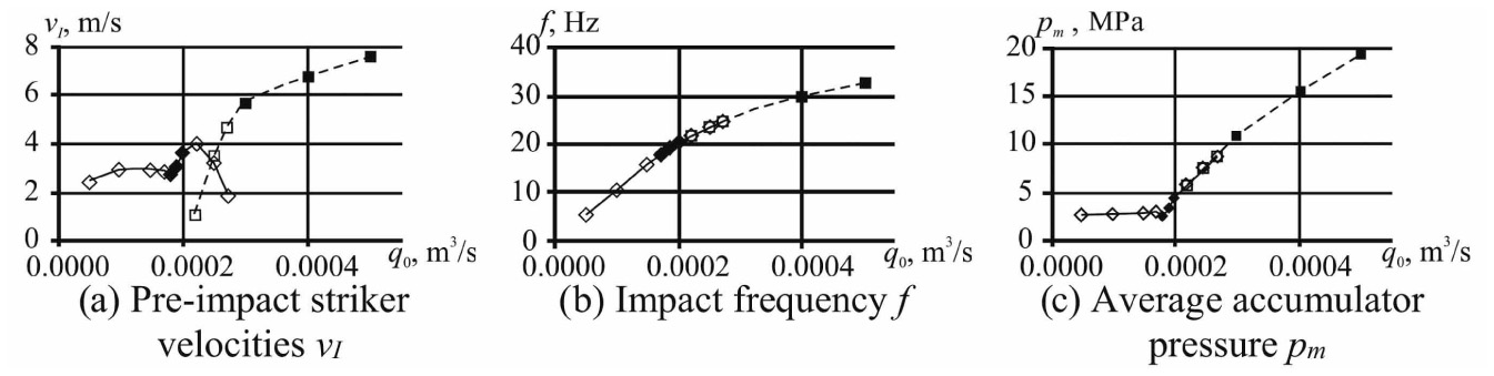
Figure 6 Dependencies hydro-impact system characteristics on flow rate q0: 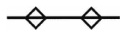 – multi-impact or double-impact mode, strikes in forward direction,
 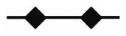 – single-impact mode, strikes in forward direction,
  – single-impact mode, strikes in backward direction,
  – double-impact mode, strikes in backward direction.
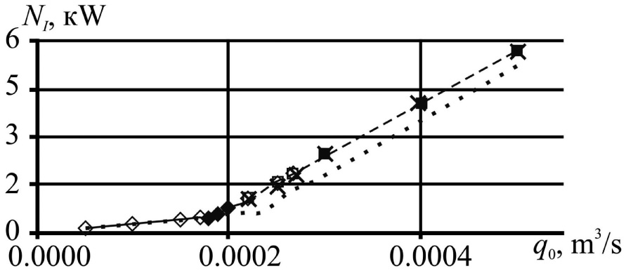
Figure 7 Dependencies of strike power N on flow rate q0. Curve legends coincide with Figure 6 legends for coordinate x2 = 0.03 m; ⋯ −x2 = 0.025 m; × – calculation result for system of constant pressure.
Impact power NI can be considered as the most informative integral characteristic, which in this case was calculated by the formula
where (EI)k – energy of k-th impact in limit cycle time T. In single-impact cycles k = 1. Dependency of power N on flow rate q0 is shown on Figure 7.
The fact that flow rate increase leads to system pressure increase and growth of dynamic characteristics: frequency f and pre-impact striker velocity vI, system strike power NI, – is physically understandable. Start of such behavior belongs to the point when multi-impact mode ends.
Multi-impact mode, observed in case of low liquid flow supplied to the system, allows, due to idle (without hitting about limiter) striker movements, to keep average pressure pm (Figure 6(c)) and average pre-impact velocity vI (Figure 6(a)) on constant values. There is a change in nature of dependencies of vI, pm and strike power NI on flow rate q0 at the point of transition from multi-impact to single-impact modes (Figures 6(a,c) and Figure 7).
Change in coordinates x1 and x2, in which valve position moves from I-th to II-th and vice versa, allows to conduct setup for system integral characteristics and points, which are typical for mode transition. To illustrate it, we carried out calculation of limit cycle characteristics for same device, as in previous case, but with different coordinate x2: x2 = 0.025 m. Flow rate q0 was under modification. In the result, compared models have in general same process development and behavior of system integral characteristics. Impact power reduce is shown on Figure 7 for double-impact and single-impact direct-acting modes. Note, that impact power curve coincides with corresponding curve, obtained from calculation with x2 = 0.03 m, for multi-impact mode. Displacement of the op-modes boundaries is shown in the first (for x2 = 0.03 m) and second (for x2 = 0.025 m) rows of the table.
The existence of multi-impact cycle can be described by the process nature, which is physically defined by model of system with flow rate source. This phenomenon was experimentally proven for single-impact backward-acting system by us (Gorodilov, 2010).
Table Flow rate values of op-modes of system with a source of flow rate (1st and 2nd rows) and pressures values of op-modes of system with a source of constant pressure (3 row)
| Multi-impact | Single-impact in forward direction | Double-impact | Single-impact in backward direction | |
| x2 = 0.03 m | q0 = 0.5 · 10−3 −1.7 · 10−3 m3/s |
q0 = 1.8 · 10−3 −2 · 10−3 m3/s |
q0 = 2.1 · 10−3 −2.6 · 10−3 m3/s |
q0 = 2.7 · 10−3 −5 · 10−3 m3/s |
| x2 = 0.025 m | q0 = 0.5 · 10−3 −2.2 · 10−3 m3/s |
q0 = 2.3 · 10−3 −2.6 · 10−3 m3/s |
q0 = 2.7 · 10−3 −3.8 · 10−3 m3/s |
q0 = 3.8 · 10−3 −5 · 10−3 m3/s |
| x2 = 0.03 m | – | pn = 5.1–9.5 MPa | pn = 9.6–16.2 MPa | pn > 16.2 MPa |
5.2 Simulation with a Source of Constant Pressure
In case of system with source of constant pressure, Equations (2), (4), (5) represent equations of material point free oscillation (Landau and Lifshitz, 1976). Therefore, solution can be presented as follows:
– in case of hydraulic force (Figure 2, branch I)
| (7) |
– in case of hydraulic force absence (Figure 2, branch II)
| (8) |
where is circular oscillation frequency, λ = SApn/cm is position of static balance for striker, xk0, vk0 are striker coordinate and velocity in the beginning of current working cycle phase, tk0 is time of the phase start.
Results of calculations show, that system with giving parameters in phase of backward movement and initial conditions
overcomes coordinate −x1 (oscillatory cycle with limiter L1 hitting begins) with giving pressure pn > 5 MPa (pressures values of op-modes of system presented at the last row of the Table).
When pressure increases above 9.5 MPa, system starts its transition to double-impact regime, and when pressure is 16.2 MPa and above – to single-impact with limiter L2 impact. Pressures values of the op-mode boundaries is shown in the third row of the table. Results of impact power, obtained in calculations for model under consideration, in coordinates q0−NI, are outlined in Figure 7. Pressure pn in Equations (7), (8) was assumed as average pressure pm, obtained in calculations for model with flow rate source q0 (Figure 7).
In calculations one can observe good agreement in power data for both models. But apparently, in model with source of constant pressure the value of this pressure is unknown from the beginning, because it is defined by process dynamics, which, in its turn, depends of giving system parameters. Also note, that process definition is incorrect, in particular, multi-impact mode is unachieved and oscillatory process can be observed only for pressure values pn > 5 MPa.
6 Conclusion
The possibility of implementation of reversible single-acting hydro-impact system is proven by conducted researches. In order to do that, two limiters of striker movement must be embedded into device construction.
System characteristics and working mode variation is possible in single device and can be achieved by liquid flow rate change, from the one side, and, from the other side, by setup of striker position, in which hydraulic chamber connects with pressure and drain lines.
Results of calculations for specific typical system show that change in flow rate leads to modification of auto-oscillatory limit cycles.
At low flow rate multi-impact mode is observed. Flow rate increase leads, firstly, to transition to single-impact mode with forward direction of striker movement, then to double-impact mode with impacts in both directions, and, finally, to single-impact mode with backward striker movement direction.
When flow rate increases, system integral characteristics also increase, such as pre-impact velocity and strikes frequency, pressure in system, impact power.
Acknowledgement
This work was supported by the FSR under project No AAAA-A17-117122090003-2.
Nomenclature
| F | force, acting on striker |
| m | striker mass |
| x1, x2 | coordinates, in which force changes its sing |
| L1, L2 | striker movement limiters |
| V | valve |
| U | valve control line |
| C | body frame |
| P | piston-striker |
| S | spring |
| M | accumulator |
| q0 | flow rate |
| pn | nominal pressure of source of constant flow rate |
| η0 | efficiency of source of constant flow rate |
| r0 | hydraulic resistance |
| cm | spring stiffness |
| x3 | preload deformation of spring |
| SA | striker area from the side of chamber A |
| xL2 | limiter L2 coordinate |
| R | striker velocity coefficient of restitution |
| x и v | coordinate and velocity of striker |
| t | time |
| cM | accumulator spring stiffness |
| SM | accumulator piston area |
| vI | pre-impact velocities |
| f | impacts frequency |
| pm | average accumulator pressure |
| NI | impact power |
| k | circular oscillation frequency |
| λ | position of static balance for striker |
| x0, v0 | initial striker coordinate and velocity |
| xk0, vk0 | striker coordinate and velocity in the beginning of current working cycle phase |
| tk0 | phase start time |
References
Alimov, O. D. and Basov, S. A. (1990) Hydraulic Vibro-Impact Systems (in Russian). Nauka. Moscow.
Arushunyan, O. B. and Zaleytcin, S. F. (1990) Numerical Solution of Ordinary Differential Equations on the Fortran Language (in Russian). Moscow: Moscow ST.Univ.
Babitsky, V. I. (2013) Theory of vibro-impact systems and applications. Springer Science & Business Media.
Besekerskii, V. A. and Popov, E. P. (2004) Theory of Automatic Control Systems (in Russian), Google Scholar. Moscow: Professiya.
Ficarella, A., Giuffrida, A. and Laforgia, D. (2006) ‘Numerical investigations on the working cycle of a hydraulic breaker: Off-design performance and influence of design parameters’, International Journal of Fluid Power, 7(3), pp. 41–55. doi: 10.1080/14399776.2006.10781257.
Franco, W. and Ferraresi, C. (2017) ‘A model-based methodology for rapid designing of hydraulic breakers’, International Journal of Fluid Power, 18(2), pp. 102–110. doi: 10.1080/14399776.2016.1270704.
Giuffrida,A. and Laforgia,D. (2005) ‘Modelling and simulation of a hydraulic breaker’, International Journal of Fluid Power, 6(2), pp. 47–56. doi: 10.1080/14399776.2005.10781219.
Gorodilov, L. V. (2005) ‘Mathematical models of hydraulic percussion systems’, Journal of Mining Science, 41(5), pp. 475–489. doi: 10.1007/s10913-006-0010-2.
Gorodilov, L. V. (2010) Development of Principles of the Theory on Hy-dropercussion Systems for Mining and Construction Machines: Dr. Eng. Extended Abstracts (in Russian). N.A. Chinakal Institute of Mining, SB RAS.
Gorodilov, L. V. (2012) ‘Analysis of the dynamics of two-way hydropercus-sion systems. Part I: Basic properties’, Journal of Mining Science, 48(3), pp. 487–496. doi: 10.1134/S1062739148030124.
Gorodilov, L. V. (2018) ‘Analysis of Dynamics and Characteristics of Main Classes of Self-Oscillating Volume-Type Hydraulic Impact Systems’, Journal of Machinery Manufacture and Reliability, 47(1), pp. 19–27. doi: 10.3103/S1052618818010077.
Gorodilov, L. V., Vagin, D.V. and Rasputina, T. B. (2017) ‘Development of the Procedure, Algorithm and Program to Select Basic Parameters of Hydraulic Percussion Systems’, Journal of Mining Science, 53(5), pp. 855–860. doi: 10.1134/S1062739117052874.
Landau, L. D. and Lifshitz, E. M. (1976) ‘Mechanics. Vol. 1’, Course of Theoretical Physics Ser Vol. 1. doi: 10.1016/j.jcis.2010.07.069.
Lekontsev, Y. M. and Sazhin, P. V. (2014) ‘Directional hydraulic fracturing in difficult caving roof control and coal degassing’, Journal of Mining Science, 50(5), pp. 914–917. doi: 10.1134/S106273911405010X.
Manzhosov, V. K. and Novikov, D. A. (2015) Simulation of transients and limit cycles of motion of vibro-impact systems with discontinuous characteristics (in Russian). Ulyanovsk: UlSTU.
Melamed, Y. et al. (2000) ‘Hydraulic hammer drilling technology: Developments and capabilities’, ASME Journal of Energy Resources Technology, 122(1), pp. 1–7. doi: 10.1115/1.483154.
Biography

Leonid V. Gorodilov was born in 1956 in Glazov, Russian Federation. He qualified as a specialist in the field of Physical processes of mining in the Moscow mining institute in 1979. Leonid V. Gorodilov in 1993 received a PhD degrees in Fluid mechanics, gas and plasma from the Institute of hydrodynamics SB RAS. In 2010, he received a Dr. of Engineering degrees in Mining machinery from the Institute of mining of SB RAS. Since 1985 he has been working at the Institute of mining SB RAS, currently he is the Head of the laboratory of Pulse systems modeling. Dr. L. Gorodilov is currently engaged in research in the field of hydraulic impact systems for mining and mechanics of impact destruction of rocks.
International Journal of Fluid Power, Vol. 20_2, 209-224.
doi: 10.13052/ijfp1439-9776.2023
© 2019 River Publishers