Design and Characterization of a Five-Chamber Constant-Volume Hydraulic Actuator
Beau Johnson*, Harrison Bartlett and Michael Goldfarb
Mechanical Engineering, Vanderbilt University, 2400 Highland Ave, Nashville, TN 37212, USA
E-mail: beau.p.johnson@vanderbilt.edu, harrison.l.bartlett@vanderbilt.edu, michael.goldfarb@vanderbilt.edu
* Corresponding Author
Received 28 January 2019; Accepted 21 October 2019; Publication 20 November 2019
Abstract
This paper describes a new design for a constant-fluid-volume, also known as a symmetrical, hydraulic cylinder. In contrast to the two fluid volume chambers of a typical hydraulic cylinder, the constant-fluid-volume cylinder contains five potential fluid chambers. Relative to three and four chamber designs, both previously described in the engineering literature, the five chamber design enables a minimum-diameter solution with a simpler porting implementation. Following a general description of the five-chamber design and its motivation, a five-chamber cylinder prototype is described and presented. Experimental results are presented comparing some behavioral characteristics of the five-chamber cylinder to a double-rod cylinder, and to two variations of single-rod implementations. Finally, a minimum-diameter five-chamber cylinder variant is described, and its geometric characteristics compared to equivalent double-rod and four-chamber cylinder implementations.
Keywords: Actuators, cylinder, damping, power generation, hydraulic systems.
1 Introduction
Hydraulic actuation systems provide among the highest force and power density of any actuator. Among the most commonly used hydraulic actuators is the single-rod hydraulic cylinder. Such cylinders are often employed in an actuation system that includes a pump, accumulator, and reservoir, along with a separate directional control valve for each cylinder. In this type of system, the pump and accumulator together provide a pressure source, and the directional control valve meters hydraulic fluid between the pressure source and one side of the hydraulic cylinder, and between the opposing side of the cylinder and the reservoir, from which the pump draws hydraulic fluid. For purposes of this paper, this type of hydraulic system is considered an “open” hydraulic system, since the reservoir is able to accommodate the variable fluid volume associated with movement of the single-rod cylinder (i.e., the amount of fluid in the reservoir will increase when the cylinder is fully retracted, and will decrease when it is fully extended).
In contrast to open-type hydraulic systems, some hydraulic actuators operate within a “closed” hydraulic system, in which the system does not include a fluid reservoir, and therefore is not able to directly accommodate fluctuations in fluid volume. A common closed-type hydraulic actuation system is a hydrostatic transmission (e.g., (Manring and Luecke, 1998; Kugi et al., 2000)), which typically employs rotary piston pumps and motors in a closed hydraulic system to transmit (rotational) shaft power between a hydraulic pump and motor. Since rotary piston pumps and motors are constant-volume hydraulic elements, no accommodation of variable fluid volume is required.
Although rotary-type hydrostatic actuation systems are common, a similar “closed” system approach can also be applied to linear actuation systems. Such systems can offer potential advantages relative to open-type linear actuation systems, such as the potential for greater efficiency and better leveraging of electrical power distribution, combined with the force density of hydraulic cylinders, providing benefits in applications including mobile robotics (Semini et al., 2017), prosthetics (Bellmann and Blumentritt, 2009), and flight control applications (Van Den Bossche, 2006). Discussion of the framework and characteristics of such systems is given in Habibi (1999, 2000, 2006) and Kolks and Weber (2018). As described in these references, due to the absence of a fluid reservoir in a closed system, an important component of a hydrostatic actuation system is a “symmetrical actuator,” which is a hydraulic actuator characterized by a constant fluid volume as a function of stroke. This type of actuator is referred to as a “constant-volume hydraulic actuator” (CVHA) here, since the amount of fluid contained within the actuator must always be constant over the full cylinder stroke.
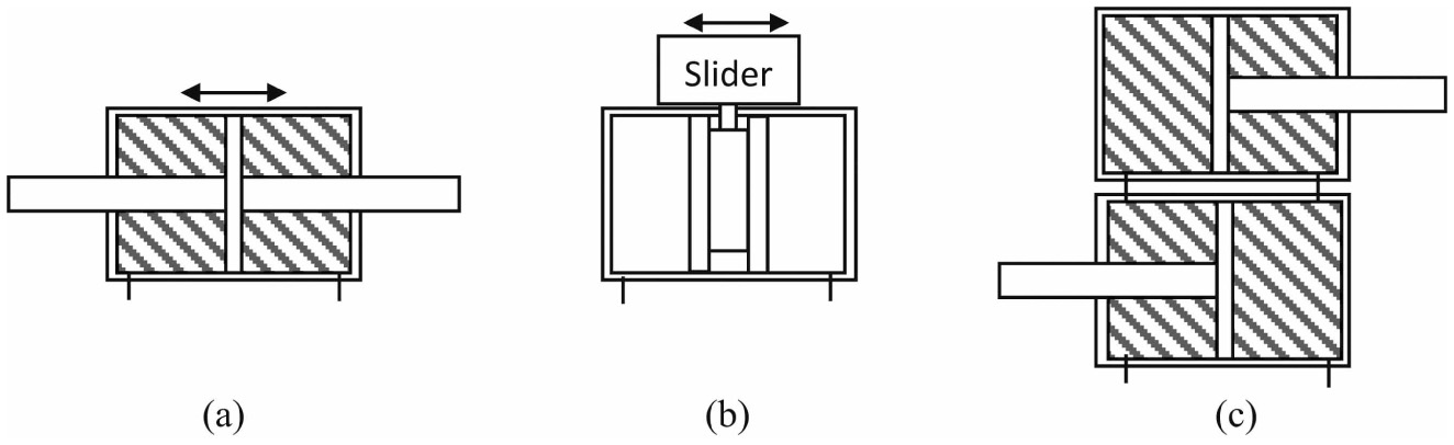
Figure 1 Schematic diagram of symmetric linear actuators: (a) double rod cylinder, (b) rodless cylinder, and (c) tandem cylinder.
The most common CVHA is a double-rod cylinder (Figure 1(a)), which mirrors the piston rod about the piston, such that a cylinder rod extends from the piston through each end of the cylinder and maintains a constant fluid volume over the stroke. Although this type of cylinder provides constant fluid volume, it also requires a design envelope that must accommodate the stroke length of the piston extended symmetrically on both sides of the cylinder, and thus requires a considerably larger design envelope, relative to a single-rod cylinder, for the same nominal output characteristics. Additionally, fewer options are available with respect to mounting such a cylinder, particularly since bending moments on the piston rods must generally be avoided. Arodless cylinder (Figure 1(b) is another cylinder configuration that provides a constant fluid volume. Rather than use a piston rod that extends axially through the end of the cylinder to transmit power to an external point of attachment, a rodless cylinder incorporates a carriage attached to the piston laterally through the wall of the cylinder. This configuration provides constant fluid volume, but the nature of sealing along the length of the cylinder limits its use to very low pressures, relative to rod-type cylinders. As such, performance with rodless cylinders is compromised substantially, relative to rod-type cylinders.Another cylinder configuration that provides constant fluid volume is a tandem cylinder configuration (Figure 1(c)) (Beater, 2007), which employs a pair of single-rod cylinders in which each end of one cylinder is in fluid communication with the corresponding end of a duplicate cylinder. Given this configuration, retraction of the rod in one cylinder is accompanied by extension of the rod in the other cylinder, and the coupled motion results in a constant fluid volume. In this configuration, only one of the two cylinders is used for actuation, while the other is used strictly to maintain a constant fluid volume, and as such, this configuration effectively doubles the size and weight of the actuator.
2 Constant Volume Single-Rod Cylinder
In order to provide a constant fluid volume linear actuator without the size, weight, packaging, and/or performance penalties associated with the aforementioned actuators, researchers have proposed alternative CVHA designs. Among the unifying aspects of these designs is the fact that, rather than two fluid chambers as is characteristic of typical hydraulic cylinders, these designs incorporate multiple fluid chambers. Specifically, previously-published multi-chamber cylinders contain either three fluid chambers (i.e., the designs described by Habibi (1999, 2000, 2006) and Pastrakuljic (1995)) or four (i.e., the designs described by Linjama et al. (2009, 2015), Heybroek and Norlin (2015) and Wu et al. (2016)). Figure 2(a) and (b) schematically depict the designs of the three and four chamber hydraulic cylinders, respectively. Note that, although a subset of the three or four chambers can be pressurized, implementation of these designs as a CVHAis subject to the following two essential symmetry conditions: (1) pressurization of at least one chamber must extend the piston rod, while pressurization of at least one other chamber must retract it; and (2) the effective area on the extension portion of the piston must equal the effective area on the retraction portion. For example, for the three-chamber design in Figure 2(a), only chamber 2 retracts the rod, and therefore chamber 2 must always be used. Although both chambers 1 and 3 extend the rod, it is not physically possible to establish equal piston areas between chambers 1 and 2 (due to the piston rod), since the area 1 will always be greater than area 2. As such, the only valid (two-pressure) combination is to use chamber 3 to extend the rod and 2 to retract it (while chamber 1 is left vented to atmosphere), where the piston and cylinder are designed such that piston areas exposed to chambers 2 and 3 are equal. In the case of the four-chamber cylinder (Figure 2(b)), the summation of areas of 2 and 4 (the retraction chambers) will always be less than area 1, and therefore (as in the three-chamber design) chamber 1 cannot be used. As such, chamber 3 must be used for extension, and retraction can either be restricted to either chamber 2 or chamber 4, or the combination of the two. Employing the combination of the two will enable a smaller overall cylinder diameter, since it more completely fills the rod-side of the piston with fluid. Specifically, in addition to the conditions for symmetry previously stated, in order to provide a minimum-diameter solution, the rod-side of the piston must be fully filled with pressurized fluid. Such is the chief advantage of a four-chamber design relative to the three-chamber design (i.e., smaller achievable theoretical diameter). This theoretical advantage, however, requires a more complex porting geometry, since simultaneous access to both chambers 3 and 4 in a compact space is a challenge (i.e., these ports would most likely be located in the center of the cylinder, which increases the cylinder diameter). As such, the theoretical advantage of the four-chamber design relative to the three-chamber design may not be realized, depending on the nature of the application.
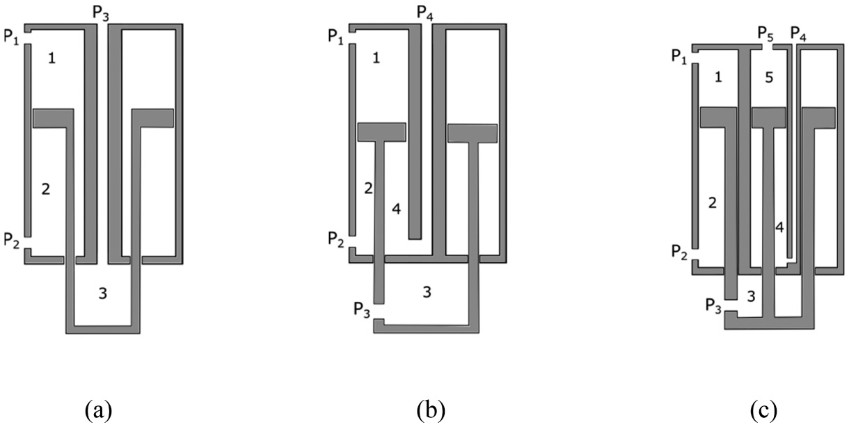
Figure 2 Schematic diagram of multi-chamber constant-fluid-volume linear cylinder actuators, specifically: (a) three-chamber cylinder, (b) four-chamber cylinder, and (c) five-chamber cylinder as described here.
This paper proposes a new CVHA cylinder design, shown in Figure 2(c), which incorporates five chambers. The inclusion of five chambers enables a combination of chambers that satisfies both the symmetry conditions of a CVHA, and satisfies the minimum diameter condition for a CVHA, without requiring use of chamber 3, which alleviates substantial challenges associated with porting. Specifically, meeting the minimum diameter criterion requires the use of chambers 2 and 4. Unlike the three and four chamber designs, however, the symmetry requirement can be satisfied using strictly chamber 1 to balance the piston area associated with chamber 2 and 4, and therefore chamber 3 need not be used. The result is a minimum diameter design with relatively simple porting, as described subsequently in this paper.
This paper presents two variations of the novel 5-chamber cylinder design: a “simplest porting” configuration, and a “minimum-diameter” configuration. Aprototype of the simplest-porting variation was constructed, and experiments were conducted to validate the behavioral characteristics of the actuator, relative to standard single-rod and double-rod cylinder configurations. Following presentation of the experimental results, the minimum-diameter design variation is described, and the resulting cylinder size is compared to that of a single-rod cylinder, and to the simplest-porting variation of the 5-chamber actuator.
3 Prototype Five-Chamber Cylinder Design
In order to experimentally validate the five-chamber concept, a five-chamber cylinder was designed, fabricated, and experimentally tested. Note that the prototype was designed as a relatively low-pressure cylinder (i.e., ∼20 bar), which simplified construction and testing. Since the constant-volume characteristics of the cylinder are independent of pressure, the low-pressure prototype does not substantially compromise the experimental validation of constant-volume behavior.
Since multiple variations of the five-chamber design meet the aforementioned symmetry requirement, the authors selected as an initial prototype the simplest-porting variation – specifically, a variation that uses only two chambers (chambers 2 and 5), each of which can be accessed via a standard cylinder port configuration (i.e., one port in each end of the cylinder body). This cylinder variation is shown schematically in Figure 3(a), and as a solid-model design in Figure 3(b).As shown in the figures, the five-chamber design consists of a cylinder nested concentrically inside another cylinder, along with a piston and rod assembly that moves axially within the cylinders. Rather than a simple piston, as in a typical single-rod cylinder, the piston assembly in the five-chamber actuator includes a piston arranged concentrically within another piston. The inner piston has a circular cross section and moves inside the inner cylinder, while the outer piston is annular such that it moves between the inner and outer cylinder. Note that end caps are sealed with O-rings, while the piston and rod seals employ U-cup seals to reduce sliding friction. Since chambers 1, 3, and 4 were not used, vent holes in those chambers vent the respective volumes to atmosphere.
In order to compare the cylinder characteristics to a standard-sized cylinder, the dimensions of the prototype were selected to match the maximum actuation force of a 1.9 cm (0.75 in) inside-diameter hydraulic cylinder with an approximate stroke length of 4.4 cm (1.75 in). As such, the prototype was designed with an inner-cylinder bore of 1.9 cm (0.75 in) and an outer-cylinder bore of 3.2 cm (1.26 in), which resulted in a total outer-diameter of the actuator of 3.4 cm (1.34 in). The resulting actuator prototype was fabricated from 7075 aluminum, and is shown assembled in the retracted and extended positions, respectively, in Figure 4.

Figure 3 (a) Schematic depiction of the five-chamber cylinder in a “simplest porting” configuration, where the shaded regions indicate volumes that are filled with hydraulic fluid, and non-shaded regions indicate chambers vented to atmosphere. (b) Solid model of the corresponding prototype actuator, where A and B indicate complementary fluid ports. The inner piston and rod is shown in green and was fabricated separately from the annular outer piston and rod shown in blue. The inner cylinder is shown in yellow, and the outer cylinder in orange. The cylinder endcaps are shown in red and grey, respectively.

Figure 4 Functional five-chamber cylinder prototype in (a) retracted and (b) extended configurations.
4 Experimental Characterization
The behavior of the five-chamber prototype was characterized and compared to three other hydraulic actuator configurations (i.e., a total of four configurations), each under two experimental conditions. The four configurations tested, shown in Figure 5(a–d), are as follows: (a) standard double-rod cylinder; (b) standard single-rod cylinder; (c) standard single-rod cylinder with accumulator on rod-side of piston; and (d) the five-chamber prototype. All cylinders had an effective cylinder bore of 1.9 cm (0.75 in) diameter and approximately 4.4 cm (1.75 in) stroke. All cylinders were also rated for similar pressures as the prototype (i.e., ∼20 bar). In the experiment, for each cylinder configuration, the two cylinder fluid ports were connected using rigid (i.e., steel) tubing, with a ball valve positioned in between the two ports, as shown in the schematics of Figure 5. The test setup for the five-chamber case is shown in Figure 6. Given this setup, the cylinder force-displacement relationship was measured under two test conditions: (1) the cylinder ports connected with the ball valve open, and (2) the cylinder ports connected with the ball valve closed. For a constant-volume cylinder, the first condition (ball valve open) should allow free movement of the cylinder rod throughout the cylinder stroke, and as such the ideal force-displacement relationship would be zero force through the range of motion. The second condition (ball valve closed) corresponds to what is commonly called a “hydraulic lock,” where the desired behavior is to be locked against motion in both directions. As such, the two experimental conditions are essentially complements: the first should produce (approximately) zero force, while the second should provide (approximately) zero motion.
In order to measure the force-displacement relationship for each, a test setup was constructed using a string potentiometer (Space Age Controls L021-00) to measure actuator displacement, and using a load cell (Transducer Techniques MLP500) in series with the actuator to measure force. Forces were applied bidirectionally to the actuator rod manually using a lever press connected to each cylinder rod. For the valve-open (VO) test condition, the lever press was used to incrementally move the rod through its range of motion in approximately 4 mm increments, stopping to measure displacement and force at each increment. This process was repeated throughout the range of motion, or until the load cell measured 500 N, whichever came first. Note that taking the measurements at zero velocity avoided viscous damping effects. This process was repeated for three cycles of measurement (i.e., three actuator strokes). For the valve-closed (VC) test condition, the piston was started in the center of the stroke when the ball valve was closed, and the lever press was subsequently used to apply forces bidirectionally in approximately 50 N increments, up to 500 N. This process was repeated for three cycles. For each test condition, the displacement and force measurements were recorded by an oscilloscope, saved to digital storage media, and were subsequently plotted using MATLAB.
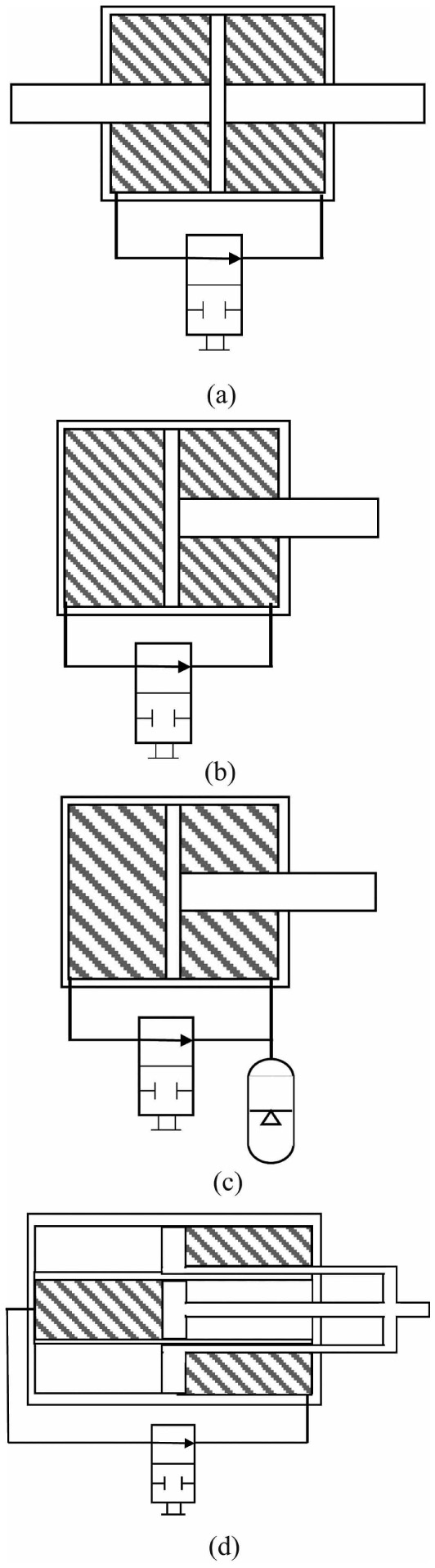
Figure 5 Schematic diagrams of four hydraulic actuator configurations used in experimental comparisons: (a) double rod cylinder, (b) a single rod cylinder, (c) singe rod cylinder with accumulator attached to the rod end, and (d) five-chamber CVHA. All cylinders were tested under two conditions: (1) ball valve open, and (2) ball valve closed.
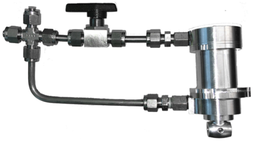
Figure 6 Five-chamber prototype shown in closed test circuit with ball valve in between cylinder ports. The capped connected shown was used for filling, but sealed off during the experimental characterization.
5 Results
The experimental results for each case shown in Figure 5 and for both the VO and VC test conditions are shown in Figure 7, with force plotted on the vertical axis and position plotted on the horizontal axis. Positive force values indicate tensile rod force and negative forces indicate compressive force. The middle of the stroke for each cylinder corresponds to a position of zero, such that positive displacement values represent extension and negative displacement values represent retraction.
As shown in the top row, the double-rod cylinder is characterized by near ideal constant-volume behavior (i.e., near zero-force in the VO condition, and near zero-displacement in the VC). Note that the cylinder differs only slightly from the ideal, due to seal friction in the VO case, and due to fluidic, structural, and seal compliance in the VC case. The second row in Figure 7 shows the results of the same tests performed on the single-rod cylinder. In this case, as shown in the VC case (second column), the single-rod cylinder provides a near ideal hydraulic lock behavior. As shown in the first column, however, due to the non-constant-volume (i.e., non-symmetric) nature of the single-rod cylinder, it fails to provide appropriate zero-force behavior in the VO case. Rather, in the rod retraction direction the cylinder is essentially locked, since the rod volume cannot be introduced into the closed volume of the fluid circuit. The rod is able to move in the rod extension direction, although doing so creates a vacuum in the fluid that acts to pull the rod towards the zero position. As such, the single-rod is unable to provide appropriate constant-volume behavior. The problem of variable fluid volume can be accommodated via use of an accumulator on the rod-side of the cylinder, as illustrated in Figure 5(c), which is the configuration tested in the third row of Figure 7. In this case, under the VO condition, the rod is able to move throughout the stroke with near ideal (i.e., zero-force) behavior, since the accumulator accommodates the change of fluid volume introduced by the piston rod. As seen in the second column, however, the system is unable to provide a bidirectional hydraulic lock in the VC case. Rather, the system is able to provide a hydraulic lock against retraction, but can at most sustain a vacuum against rod extension. Finally, the last row in Figure 7 shows the VO and VC cases for the five-chamber prototype. As can be seen in the figure, the prototype, like the double-rod cylinder, provides essentially ideal constant-volume behavior under both test conditions.Amore direct comparison of the data comparing only the double-rod and five-chamber results under both conditions is shown in Figure 8. As seen in the figure, both provide essentially identical behavior, different from the ideal only in seal friction for the VO condition, and system compliance for the VC condition.
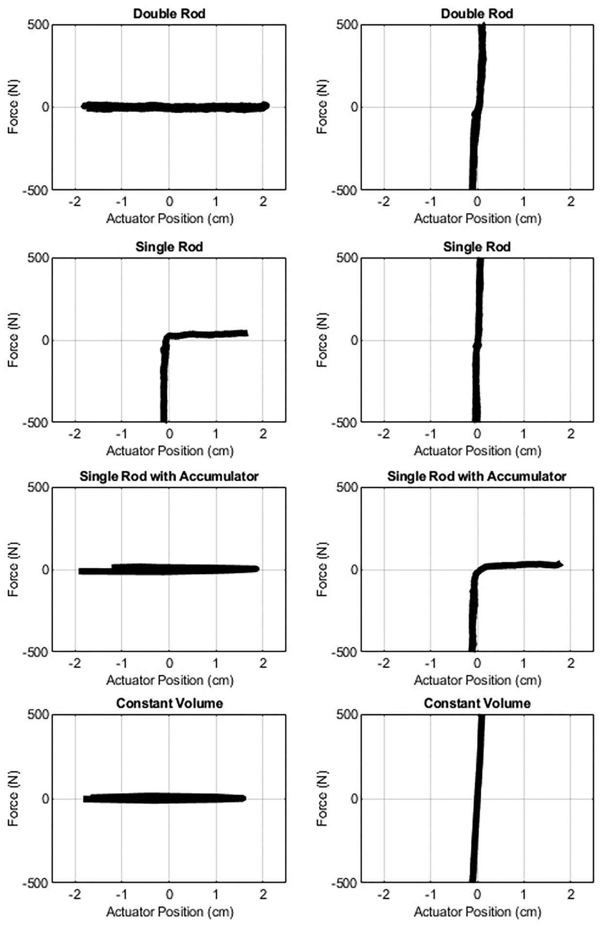
Figure 7 Experimental force-displacement results for each test configuration shown in Figure 5, under both valve open (shown left) and valve closed (right) test conditions.
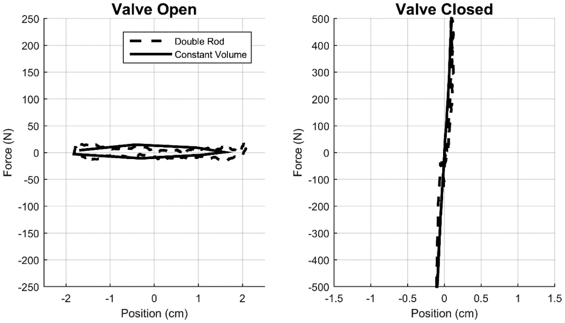
Figure 8 Direct comparison of double-rod cylinder and five-chamber configurations under both VO and VC test conditions.
6 Discussion
6.1 Test Results
As shown in the data of Figure 7, the single-rod variants are unable to provide appropriate constant-volume behavior. Specifically, although an accumulator allows the free motion condition desired in the VO test condition, it precludes a bidirectional hydraulic lock in the VC condition. Although the accumulator case tested here was at atmospheric pressure, one could alternatively use a gas-charged or spring-charged accumulator. Doing so would improve the behavior in the VC condition, but at the cost of compromising the behavior in the VO condition. As the accumulator stiffness increases from zero (as tested) to ideally infinite, the behavior of the single-rod system with accumulator transitions from the second row in Figure 7 to the first, where the ideal VC behavior is restored as the ideal VO behavior is lost.
As shown in Figure 8, the five-chamber and double-rod behaviors are essentially identical. Therefore, the primary difference between these two actuators is the geometric envelope each requires, and the associated mounting conditions. Specifically, the five-chamber design requires an increased diameter relative to its single-rod counterparts, but requires substantially less axial length than an equivalent double-rod cylinder, and also enables in most cases simpler mounting arrangements.
6.2 Minimum-Diameter Design
Recall that the five-chamber prototype was configured using chambers 2 for retraction and 5 for extension, since that configuration was relatively simple to implement, and thus selected for the experimental proof of concept. As previously mentioned, however, that variation does not satisfy the minimum-diameter criterion, which requires that the rod-side of the piston be fully filled with pressurized fluid. Doing so requires the use of both chambers 2 and 4 for retraction, which in the five-chamber design can be balanced by using chamber 1 for extension, as illustrated schematically in Figure 9. In this configuration, chambers 2 and 4 are in fluid communication, which is enabled by: (1) ports between chambers 2 and 4 near the rod seals and (2) ports in the outer piston rod near the piston. Note that, additionally, the outer piston rod can be constructed from several different rods, rather than a single annular rod. Configuring the chamber 1 piston area to equal the combined chambers 2 and 4 piston area will satisfy the symmetry condition and provide CVHA behavior. A cylinder of the same fluid dimensions as those tested, i.e., effective bore of 1.9 cm (0.75 in) and stroke of 4.4 cm (1.75 in), can be constructed with this design with a bore diameter of 2.0 cm (0.8 in). By comparison, the proof-of-concept prototype shown in Figures 3 and 4 required a bore diameter of 3.1 cm (1.22 in).
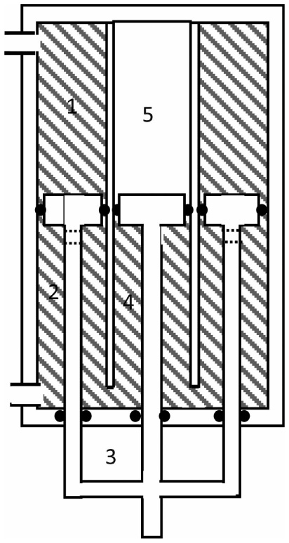
Figure 9 A schematic representation of a minimum-diameter variation of the five-chamber actuator.
6.3 Comparing Characteristics of Different CVHAs
In order to provide some relative insight into the comparative design characteristics, equivalent double-rod, four-chamber, and (minimum-diameter) five-chamber (Figure 9) cylinders were compared. These were compared based on swept volume, swept profile, and linear sealing burden.
6.3.1 Swept volume and profile comparison
The theoretical design envelope differences can be compared by considering the bore and the total stroke length. For a 1.9 cm (0.75 in) bore, 4.4 cm (1.75 in) stroke cylinder, an equivalent double-rod cylinder with a 0.64 cm (0.25 in) rod has a bore of 2.0 cm (0.8 in) and swept stroke length of 8.8 cm (3.5 in). An equivalent minimum-diameter cylinder can be constructed by using the same rod area as the double-rod cylinder, and using a standard cylinder wall thickness (i.e., 1.25 mm or 0.05 in) for the internal cylinder wall. Doing so yields a minimum-diameter configuration with an outer bore of 2.1 cm (0.83 in) and swept stroke length of 4.4 cm (1.75 in) for both a four-chamber cylinder and five-chamber cylinder. Note that the outer wall thickness is excluded from these comparisons, since it should be essentially equal for all cylinders, since all would presumably be made of the same material, rated at the same pressure, and all have outer bore diameters that are approximately equal. As such, in terms of profile, the double-rod requires 17.6 cm2 (2. in2) while the four-chamber and five-chamber both require 9.2 cm2 (1.43 in2). In terms of swept volume, defined as the actual cross-section swept through the rod movement, the double-rod requires 27.6 cm3 (1.76 in3), while the four-chamber and five-chamber require 15.2 cm3 (0.93 in3). As such, for the example design considered, the four-chamber and five-chamber designs require approximately 53% of the swept profile and approximately 55% of the swept volume, relative to the double-rod type. As such, both the four and five-chambers designs provide substantially greater design compactness.
6.3.2 Linear sealing burden
In order to compare the amount of sealing required, which presumably is related to the amount of seal friction, the amount of linear seal required for each cylinder type was calculated. For the different cylinder types compared above, the double rod cylinder requires 5.3 cm (2.1 in) of linear seal, the five-chamber requires 7.1 cm (2.8 in), and the four-chamber cylinder requires 8.4 cm (3.3 in). Therefore, both the multi-chamber cylinders entail an increased sealing burden relative to the double-rod; in this example, the five-chamber requires 34% more linear seal contact, while the four-chamber requires 58% more linear seal contact. As a first-order approximation, one can also assume that the five-chamber and four-chamber designs will entail a 34% and 58% increase in seal friction, respectively, relative to the double-rod cylinder.
6.3.3 Chamber 3
As previously mentioned, the four-chamber requires use of chamber 3, while the five-chamber does not. As such, the four-chamber requires the use of an annular piston rod, while the five-chamber can replace the annular piston rod with a plurality (e.g., three) standard cylinder rods, which are most likely easier to seal and simpler to manufacture in an accurate manner.
The utilization of chamber 3 additionally requires the four-chamber design to accommodate the movement of a fluid port throughout the stroke of the cylinder and requires internal porting to access the fluid volume housed in chamber 4. Conversely, with the use of a plurality of standard rods in place of an annular rod, chambers 2 and 4 in the five-chamber design are naturally integrated, and therefore chamber 4 no longer requires porting. As such, the minimum-diameter design of the five-chamber with a plurality of standard rods requires porting of chambers 1 and 2, which are the standard ports in a double-acting hydraulic cylinder.
Table 1 Comparison of the relative dimensions and sealing burden of the five-chamber, four-chamber, and double rod cylinder with equivalent effective cross-sectional areas
| Cylinder | Bore cm (in) | Stroke cm (in) | Profile cm2 (in2) | Swept Volume cm3 (in3) | Linear Sealing cm (in) |
| Five-Chamber | 2.1 (0.83) |
4.4 (1.75) |
9.2 (1.43) |
15.2 (0.93) |
7.1 (2.8) |
| Four-Chamber | 2.1 (0.83) |
4.4 (1.75) |
9.2 (1.43) |
15.2 (0.93) |
8.4 (3.3) |
| Double-Rod | 2.0 (0.8) |
8.8 (3.5) |
17.6 (2.8) |
27.6 (1.76) |
5.3 (2.1) |
7 Conclusion
The authors have presented a new five-chamber hydraulic cylinder design that provides symmetrical (i.e., constant-volume) behavior in a single-rod package. Relative to a double-rod cylinder alternative, the five-chamber cylinder offers improved design compactness (i.e., reduced swept volume), although at the expense of a greater sealing burden and likely increase in corresponding friction. Relative to a four-chamber constant-volume design, the five-chamber offers equivalent compactness, but a lower sealing burden and presumably lower associated seal friction, and also offers a standard porting arrangement into the cylinder housing. As such, the proposed five-chamber design offers a reduced design volume relative to double-acting cylinders, and offers a reduced seal burden and ease of porting relative to four-chamber designs.
Acknowledgements
This work was supported by The U.S. Department of Defense under DOD contract no. W81XWH-15-2-0068, and by an award from the Vanderbilt School of Engineering Dean’s Office.
References
Beater, P., 2007, Pneumatic Drives. Springer, Berlin, Heidelberg, Chap. 9.
Bellmann, M. and Blumentritt, T. S. S., 2009, “Functional principles of current microprocessor-controlled prosthetic knee joints,” Orthopädie Technik, 29, pp. 1–6.
Habibi, S. and Goldenberg, A.A., 1999, “Design of a new high performance electrohydraulic actuator,”International Conference on Advanced Intelligent Mechatronics, IEEE/ASME, Atlanta, GA, USA, 1999, pp. 227–232.
Habibi, S. and Goldenberg, A.A., 2000, “Design of a new high-performance electrohydraulic actuator.” IEEE/ASME transactions on mechatronics, 5(2), pp. 158–164.
Habibi, S., Burton, R., and Sampson, E., 2006, “High precision hydrostatic actuation systems for micro-and nanomanipulation of heavy loads.” Journal of dynamic systems, measurement, and control, 128(4), pp. 778–787.
Heybroek, K. and Norlin, E., 2015, “Hydraulic multi-chamber cylinders in construction machinery.” Hydraulikdagarna, Sweden Mar 16–17.
Kolks, G. and Weber, J., 2018, “Symmetric Single Rod Cylinders with Variable Piston Area? A Comprehensive Approach to the Right Solution.” BATH/ASME 2018 Symposium on Fluid Power and Motion Control, ASME, pp. V001T01A006–V001T01A006.
Kugi A., Schlacher K., Aitzetmüller H., and Hirmann G., 2000, “Modeling and simulation of a hydrostatic transmission with variable-displacement pump.” Mathematics and computers in simulation, 53(4), pp. 409–14.
Linjama, M., Paloniitty, M., Tiainen, L., and Huhtala, K. 2015. “Mechatronic design of digital hydraulic micro valve package.” Procedia Engineering, 106, pp. 97–107.
Linjama, M., Vihtanen, H.P., Sipola, A., and Vilenius, M. 2009. “Secondary controlled multi-chamber hydraulic cylinder.” The 11th Scandinavian International Conference on Fluid Power, SICFP, pp. 2–4.
Manring, N.D. and Luecke G.R., 1998, “Modeling and designing a hydrostatic transmission with a fixed-displacement motor.” Journal of Dynamic Systems, Measurement and Control, Transactions of the ASME 120(1), pp. 45–49.
Pastrakuljic, V., 1995, “Design and modeling of a new electro hydraulic actuator.” M.S. Thesis, Department of Mechanical Engineering, University of Toronto.
Semini, C., Barasuol, V., Goldsmith, J., Frigerio, M., Focchi, M., Gao, Y., and Caldwell, D. G., 2017. “Design of the hydraulically actuated, torque-controlled quadruped robot HyQ2Max,” IEEE/ASME Transactions on Mechatronics, 22(2), pp. 635–646.
Van Den Bossche, Dominique, 2006 “The A380 flight control electrohydro-static actuators, achievements and lessons learnt.” 25th international congress of the aeronautical sciences.
Wu, X., Luo, Q., and Li, X., 2016, “The four-chamber hydraulic cylinder,” IEEE/CSAA International Conference on Aircraft Utility Systems, Beijing, China. Oct. 10–12, pp. 666–669.
Biographies

Beau Johnson received the B.S. degree in mechanical engineering from the University of Alabama at Birmingham, Birmingham, AL, USA, in 2018. He is currently working toward the Ph.D. degree in mechanical engineering at Vanderbilt University, Nashville, TN, USA. His research interests include robotics and mechatronics with an emphasis on applications for lower limb prosthetics and exoskeletons.

Harrison Bartlett received the B.S. degree in biomedical engineering from the Georgia Institute of Technology, Atlanta, GA, USA, in 2014 and the M.S. and Ph.D. degrees in mechanical engineering from Vanderbilt University, Nashville, TN, USA, in 2018. He is a co-founder of Synchro Motion, LLC, a company specializing in the design of rehabilitation robotic devices. His research interests include the mechanical design and control of assistive robotic devices as well as actuation technology.

Michael Goldfarb received the B.S. degree in mechanical engineering from the University of Arizona in 1988, and the S.M. and Ph.D. degrees in mechanical engineering from MIT in 1992 and 1994. Since 1994, he has been at Vanderbilt University, where he is currently the H. Fort Flowers Professor of Mechanical Engineering, Professor of Electrical Engineering, and Professor of Physical Medicine and Rehabilitation. His research interest is the design and control of robotic systems that interact physically with people, with a particular focus on the development of assistive devices to improve quality of life for people with physical disabilities.
International Journal of Fluid Power, Vol. 20_2, 225-244.
doi: 10.13052/ijfp1439-9776.2024
© 2019 River Publishers