Extended Analysis of a Valve-Controlled System with Multi-Chamber Actuator
Henrique Raduenz1,*, Liselott Ericson1, Kim Heybroek2, Victor J. De Negri3 and Petter Krus1
1Division of Fluid and Mechatronic Systems, Linköping University, Linköping, Sweden
2Volvo Construction Equipment, Eskilstuna, Sweden
3Federal University of Santa Catarina, Florianópolis, Brazil
E-mail: henrique.raduenz@liu.se; liselott.ericson@liu.se; kim.heybroek@volvo.com; victor.de.negri@ufsc.br; petter.krus@liu.se
*Corresponding Author
Received 17 September 2021; Accepted 30 September 2021; Publication 12 November 2021
Abstract
This paper outlines an extended analysis on how multi-chamber actuators can improve the efficiency of valve-controlled systems. Resistive control is a major source of energy losses in valve-controlled systems that share the same pump to drive multiple loads. By combining different chambers, the load on multi-chamber actuators can be transformed into different pressure and flow rate levels. This allows the adaptation of its load to the loads on other actuators. This can lead to a reduction of resistive control energy losses that occur between pump and actuators when driven simultaneously. As a case study to highlight how the system efficiency can be improved, a load sensing system with a conventional and a multi-chamber actuator is analysed. The equations that describe the system steady state behaviour are presented to evaluate the effect of the load transformations on the system efficiency. A disadvantage of such architecture is the fact that load transformations result in different actuator speeds. To reduce this effect, a compensation factor for the command signal to the proportional valve is presented. The highlight from this paper is the potential for efficiency improvement enabled by the adoption of multi-chamber actuators in a valve-controlled architecture. Further research is required for the selection of number of chambers and their areas since they directly affect the system efficiency.
Keywords: Digital fluid power, multi-chamber actuators, resistive control losses.
1 Introduction
This paper contains a more extensive analysis of the system that was first presented in [1]. Another publication from the same research group on this concept but, focused on the development of a control solution is presented in [2]. In the current publication, it is included an analysis of the system efficiency for a wider range of load scenarios. Additionally, it is presented a solution to compensate area differences to ensure a similar actuator speed for the same valve control input. Extra content is added, and the discussion is extended towards which simplifications could be done and possible limitations of the proposed concept.
This study is motivated by the fact that the use of throttle-less digital hydraulics into a valve-controlled system architecture might result in increased system efficiency. In the proposed concept a multi-chamber cylinder replaces a conventional actuator in a valve-controlled load sensing architecture. Although the full potential of throttle-less digital hydraulics to increase efficiency might not be achieved, since now it is connected to a variable pressure source, it could still result in a considerable reduction of the system energy losses.
Concepts for linear actuation in hydraulics have been designed with a conventional resistive or with a digital hydraulics approach in mind. One digital hydraulics approach was presented by Linjama et al. in [3], where the concept of a secondary controlled multi-chamber actuator is proposed. By using a parallel configuration of on/off valves, different connections between constant pressure sources and actuator chambers are obtained, resulting in discrete force levels. When comparing to a load sensing system, the authors mention that they typically have several actuators, where the supply pressure is optimized for only one of them, resulting in significant throttling losses on the control valves. This is not the case for secondary controlled actuators since the loads are decoupled.
In [4] the energy efficiency of a three-chamber actuator controlled by on/off valves is evaluated. At each control edge there is a set of valves with different flow areas. At each control mode (combination of actuator areas to pressures sources) the pressure of one of the chambers is controlled resistively through the selection of different valves, resulting in a different total flow area. The control objective is to find the mode that can drive the load but also reduce the pressure drop over the valves, therefore reducing the resistive control losses.
A similar concept as the one present in [3] is presented in [5] for the control of an excavator arm. The main difference is the additional pressure source, which results in a higher number of available force levels. The same concept is investigated in [6], but applied to the control of flight control surfaces of aircrafts. In [6] the authors presented a detailed investigation of how the areas of the actuator chambers can be determined together with an efficiency analysis. For the same load cases, the digital hydraulic actuator result in a significant reduction in energy losses in comparison to traditional servo-proportional control.
It is observed that the switching nature of these systems imposes a major challenge on the development of controllers. Aiming to find a compromise between control performance and system efficiency other researchers proposed alternative architectures that also contain means of resistive control.
In [7] the authors mention the limited finite number of discrete force levels that can be generated by digital hydraulic configurations with parallel valves. To improve the force resolution, aiming to achieve an accurate control of the actuator, the authors propose that a proportional valve should be connected to one of the chambers. Results show improved controllability while still maintaining high energy efficiency.
In [8] the authors present a model predictive control strategy for a four-chamber actuator connected to a two-pressure common pressure rail through proportional valves, a Variable Displacement Linear Actuator (VDLA). It is similar to the concept presented in [3] except for the use of proportional valves which allow resistive control between the different force levels. In a simulation study presented in [9] the effectiveness of the VDLA is shown at a system level for a hydromechanical hybrid motion system for a wheel loader. In [10] results show significant fuel efficiency improvement for an excavator with a hydraulic system architecture based on the VDLA. Although the high efficiency results might motivate a change to the architecture of hydraulic systems in mobile machines, it is noted that a significant redesign is required. It is also required a more complex control approach to achieve the desired operation performance and smoothness for the operator.
The goal of this paper is to show, through a range of load cases and combinations of chambers, that the use of multi-chamber actuators in a valve-controlled system can result in an increased system efficiency. The main objective for the multi-chamber actuator is to adapt its required pressure and flow rate to reduce resistive losses that arise when multiple loads are driven simultaneously. It is also shown how the areas can be compensated to ensure similar actuator speed for the same operator input.
This paper is organized as follows: Section 2 presents a description of the proposed concept and analysis of the connections between chambers and valve ports; Section 3 provides a discussion on problems related to control of this actuator; Section 4 presents the steady state equations used for the assessment of efficiency and analysis for the area compensation; Section 5 presents the analysis of the system, efficiency results and results for the compensation factor; Section 6 presents discussions and Section 7 the conclusions. The terms: combination of chambers and mode; are used interchangeably along the text.
2 Concept Description and Analysis
The concept of multi-chamber actuators applied to valve-controlled architectures is presented and studied in this section. Figure 1(a) shows the application of a multi-chamber actuator to an open-centre architecture. Figure 1(b) shows the application of a multi-chamber actuator to a load sensing architecture.
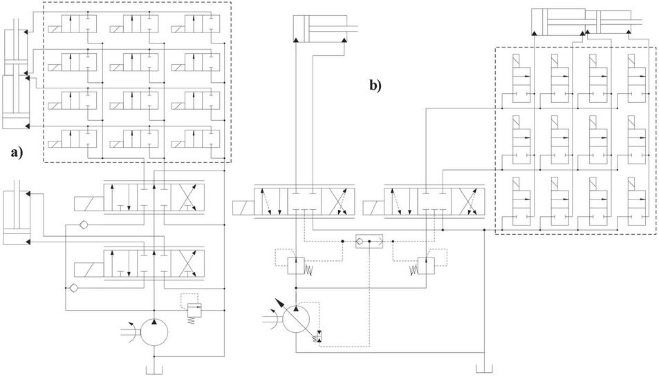
Figure 1 Proposed concept: (a) Open-centre architecture; (b) Load sensing architecture.
The fundamental idea for energy saving of such concepts is that the load on the multi-chamber actuator can be transformed to different pressure and flow rate levels. By selecting a combination of areas that result in a match of load pressures between the two actuators, the resistive losses on the control valves can be reduced.
With respect to implementation, one interesting aspect is that they do not require significant changes to the existing base architectures. The third hydraulic line connection between the on/off valves and the reservoir is necessary for two reasons. One is to avoid a high imbalance of flow rates in the ports of the proportional valve. Another is for when a flow from the reservoir is needed to fill the expanding chambers that are not connected to the proportional valve. It would be necessary to have a pressurized reservoir.
The architecture proposed in Figure 1(b) was selected to perform an analysis of its efficiency and to describe in more detail how it could be increased. A schematic diagram of the selected architecture with the main variables used in the analysis is presented in Figure 2.
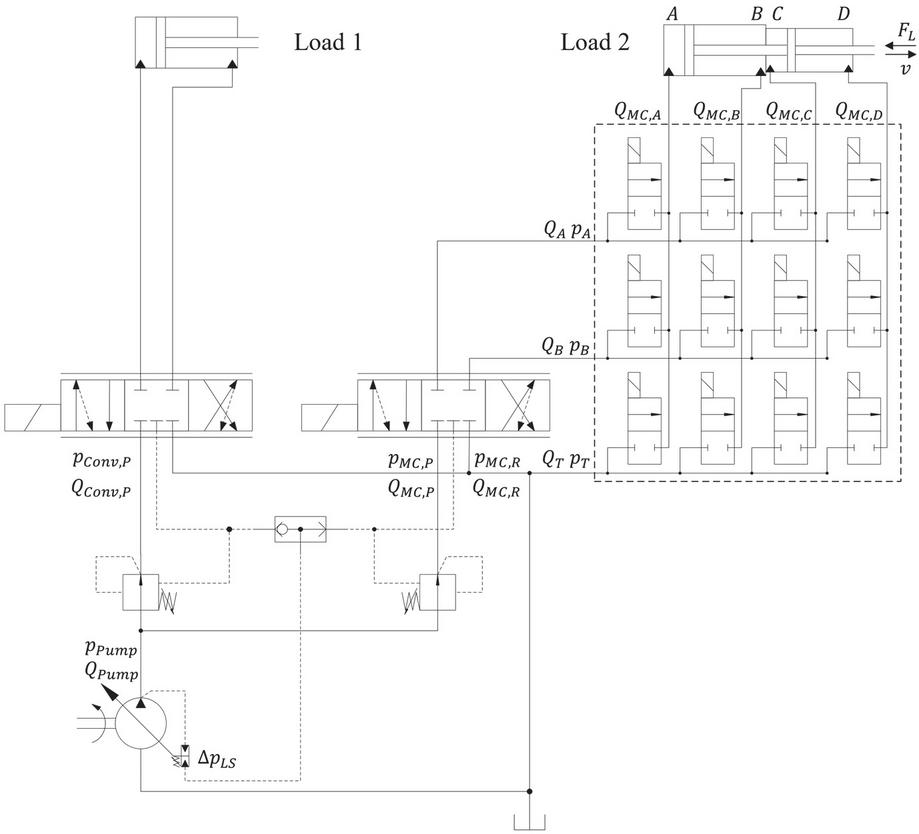
Figure 2 Selected architecture for case study.
The design parameters of the multi-chamber actuator and on/off valves are extracted from [5]. However, the difference between the concepts lies in the power supply. For the current concept, it is a load sensing architecture rather than constant pressure sources. The multi-chamber actuator presented in [5] was designed to be operated in a secondary controlled system, which would result in 81 force steps. For the current application not all modes that would be available for a secondary-controlled actuator are feasible. Most of them are excluded due to at least one of the reasons listed in the sequence:
• No flow through the port of the proportional valve
Certain modes result in no flow at one of the ports of the proportional valve and, therefore, they have been removed. Table 1 shows an example of such a situation, where no chamber is connected to the B port of the proportional valve.
Table 1 Infeasible mode due to no flow at one port of the proportional valve
| Ports | A | B | T |
| Mode | AC | – | BD |
• Flow with same direction in both ports of the proportional valve
Certain modes result in flow in the same direction in both ports of the proportional valve and, so, they have been removed. In simple terms it means, for example, that it could result in suction of flow from reservoir through the proportional valve. One example of such a situation is presented in Table 2. Chambers A and C expand or contract at the same time, resulting in flow with the same direction in both ports. The areas of the actuator determine which modes are excluded for this reason.
Table 2 Infeasible mode due to same flow direction in the proportional valve ports
| Ports | A | B | T |
| Mode | A | C | BD |
• Redundant modes when defining the actuator movement direction
The manifold of on/off valves allows each of its input ports (A/B/T) to be connected to any of the chambers, while the proportional valve can switch direction. This results in two possibilities to achieve the same actuator motion. For example, one possibility would be to maintain the proportional valve in one side and let the on/off valves change mode to achieve the different movement directions. This situation is presented in Table 3.
Table 3 Change in actuator direction of motion caused by the mode
| Ports | A | B | T | Proportional valve | Actuator Motion |
| Mode 1 | A | B | CD | PA and BT ( position) | Extend |
| Mode 2 | B | A | CD | PA and BT ( position) | Retract |
An advantage of this approach is that a 4/2 instead of a 4/3 proportional valve could be used. However, another possibility is for the proportional valve to operate in both sides for the same mode of on/off valves. This results in several redundant modes. One example of such redundancy is shown in Table 4.
Table 4 Redundant modes when operating the proportional valve in both directions
| Ports | A | B | T | Proportional valve | Actuator Motion |
| Mode 1 | A | B | CD | PA and BT ( position) | Extend |
| A | B | CD | PB and AT ( Position) | Retract | |
| Mode 2 | B | A | CD | PB and AT ( Position) | Extend |
| B | A | CD | PA and BT ( position) | Retract |
This approach seems to be a more natural one to adopt since fewer modes are needed. At the same time the proportional valve does not need to be changed or its control structure be significantly modified.
In terms of selecting which of the redundant modes to use, the decision was taken to select the ones that, for a given load in one of the four quadrants of force and speed, make the proportional valve always operate to the same side for all modes. This avoids a need for the proportional valve to change operating side if the load changes in magnitude but not the operating quadrant. Sixteen modes are thought to be feasible for this system configuration. They are presented in Table 5.
Table 5 Selected combinations of chambers
| Mode | A | B | T | Mode | A | B | T |
| 1 | A | B | CD | 9 | ABC | D | – |
| 2 | A | BD | C | 10 | ACD | B | – |
| 3 | A | D | BC | 11 | BC | D | A |
| 4 | AB | D | C | 12 | C | B | AD |
| 5 | AC | B | D | 13 | C | BD | A |
| 6 | AC | BD | – | 14 | C | D | AB |
| 7 | AC | D | B | 15 | CD | B | A |
| 8 | AD | B | C | 16 | – | – | – |
Some of these modes have flow regeneration between chambers, which results in smaller flow supply from the pump, aiding to increase system efficiency. Examples of that are modes 4 and 9 where flow from a contracting chamber fill expanding chambers.
Figure 3 shows two examples of how the configuration of digital valves result in the desired combination of actuator chambers.

Figure 3 Examples of valve configuration for: (a) Mode 6; (b) Mode 15.
3 Notes Regarding System Control
With modes to choose from comes the challenge of which one to select for the different load scenarios on the actuators and how to perform the switching between them during operation.
In a secondary controlled system, the main objective is for the actuator to achieve the desired control goal, and that would be position, speed or force. This would be achieved by switching between modes. For the current concept, the objective is also to select a mode that minimizes system energy losses. The transformation of the load, which results in smaller losses, is done while the proportional valves are still responsible for controlling position, speed or force. As will be shown in the results section, the selection of a mode to maximize the efficiency is mainly driven by the current force and speed on the actuators.
As exemplified in the analysis of the concept, most of the possible modes are in fact infeasible, redundant, or result in similar performance as will be shown in the results section. Most of them could be disregarded. In this sense, mapping system states to the most efficient mode can be simplified to a great extent. This makes the process of developing a controller a much simpler task.
Although having fewer modes to choose from, it is not a trivial task to map all possible system states to the most efficient one. It could be found through the development and implementation of an intelligent and optimisation-based controller. This would be treated as a multi-objective optimisation, where a trade-off between control accuracy of the multi-chamber actuator and system efficiency should be made. As part of the study carried out by the research group, a controller based on reinforcement learning is being studied. Initial results are found in [2]. In the current paper, the focus is on the advantage of having modes to select from and on establishing possible ways to assess which mode is the best for a certain system state.
4 System Model
As a simplification, the pressure losses on the on/off valves are considered negligible. The subscript MC refers to multi-chamber actuator and Conv to conventional actuator. The flow rate at the ports of the multi-chamber actuator is given by
| (1) |
where is the actuator speed and the negative sign tells that it is a contracting chamber for a positive speed. The flow rates at the input ports of the digital valve manifold are
| (2) |
where are binary variables that determine whether the valve that connects input port to chamber of the multi-chamber actuator is closed or open. The total chamber area connected to ports A, B and T are given by
| (3) |
Whether port A or B of the digital manifold is connected to supply or return of the proportional valve depends on its position. In this way, the flow rate from the supply port () and to the return port () of the proportional valve are given by
| (4) | ||
| (5) |
The next step is to calculate the pressures on the proportional valve ports connected to supply () and to return (). As for the flow rate, they are dependent on the proportional valve position and are calculated as
| (6) | ||
where is the load force. The pressure on the reservoir port (T) of the digital valve manifold is considered to be zero. To simplify the analysis, the load on the conventional actuator is considered to result in a pressure () and flow rate () at the supply port of the proportional valve. The pump pressure () and flow rate () are
| (7) | ||
| (8) |
where is the pressure difference for the load sensing system. The hydraulic power required by each load is calculated as
| (9) | ||
| (10) |
The hydraulic power supplied by the pump is calculated as
| (11) |
The power to drive the pump is
| (12) |
where the mechanical and volumetric efficiencies are considered to be functions of pressure and flow rate only, since a constant pump speed is adopted for this analysis. Knowing the power to each load and the power supplied by the pump, the resistive losses in the control valves between pump and actuators () are calculated as
| (13) |
By applying Equations (9) to (11) into Equation (13) and by evaluating Equation (8) for the two possible cases, the analysis can be further extended to
| (14) | ||
| (15) |
From Equations (14) and (15) it is evaluated how the selection of different chambers can affect the system efficiency. The first term of both equations indicates that the flow rate of the multi-chamber actuator should be small, which means selecting a mode with small area connected to supply. The second term of both equations indicates that having similar pressure levels would also result in a reduction of those terms, which means selecting a mode that results in as close a pressure as possible to the pressure on the conventional actuator.
Each mode changes the flow rate and pressure, so both terms of Equations (14) and (15) are affected, which means a reduction in the first might result in an increase in the second. In this sense, for every different force and speed on the actuators Equation (13) should be re-evaluated. However, the combination of chambers will also affect the efficiency of the pump, for which the power loss () is calculated as
| (16) |
The total efficiency of the hydraulic system is then calculated as
| (17) |
These equations allow the pressure and flow diagrams for the loads in each actuator to be calculated. Tor the multi-chamber actuator there will be different flow rates and pressures at the proportional valve for the different modes, as defined in Equations (4) to (6).
4.1 Compensation of Actuator Areas
A requirement for mobile machines is to reduce the workload of operators by ensuring a smooth control. For the proposed concept, each mode results in a different actuator. Here it is considered an open-loop speed control system, where the operator requests a desired actuator speed. If not compensated, the same input command from the operator results in the same opening of the proportional valve. For the same pressure drop over it, due to the pre-compensation, the flow rate would be the same. This leads to different actuator speeds for the different modes. This increases the workload for the operator that would adjust the lever command to obtain the desired speed.
This effect is somewhat straightforward to be minimized by means of adjusting the opening of the proportional valve according to the active mode. This results in a different flow rate but same actuator speed. By means of simple static equations it is shown how to adjust it by a compensation factor. A similar analysis for the specific case of a few operation modes is presented in [2].
Neglecting leakage in the actuator and digital valve block, the flow rate through the proportional valve is equal to the actuator flow rate () which is a function of speed () and area ()
| (18) |
In this case is the actuator area for the active mode, is the flow coefficient, the spool circumference, the valve opening, the fluid density and the pressure drop over the proportional valve that is regulated by the pressure compensation valve. Considering , and as constants, the actuator speed is a function of the valve opening () as
| (19) | ||
| (20) |
From Equation (19) it becomes clear the effect of the actuator area on the actuator speed. To achieve same speed for the same operator input, the opening of the proportional valve should be adjusted as
| (21) |
where is the adjusted valve opening and is the actuator area reference used to determine the speed range of the actuator for the operator inputs. In this sense, if the operator input is directly translated to a valve opening (), this signal should be compensated according to Equation (21).
5 Results
The results in Section 5.1 present a ‘Single Load Case’ where it is shown the impact of different modes on various system variables as modelled in Section 4. It is also presented an overview of how a range of non-overrunning loads over the multi-chamber actuator affect the choice of the most efficient and feasible modes, Section 5.2. And in Section 5.3, it is also presented results for the compensation signal as suggested in Section 4.1.
5.1 Single Load Case
As show in Equations (1) and (2), flow rates at the proportional valve ports are calculated directly from the actuator speed and area of the connected chambers. Results for a positive and negative actuator speed are presented in Figure 4. The opening position of the proportional valve is also shown, where 1 means PB and AT, and 1 means PA and BT. The modes on the x-axis should be read as: areas connected to ports A/B/T.
For most of the modes there is a noticeable difference in flow rate between the two ports, which is caused by the asymmetry in the chamber areas. Further comments about this difference are provided in the discussion section.
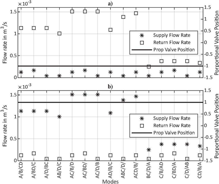
Figure 4 Flow rate at supply and return ports of the proportional valve; (a) ; (b) .
By considering a load force on each actuator, it is analysed in which conditions the selected concept could result in lower resistive losses. Two cases of actuator load forces and speeds are presented that result in a non-overrunning and an overrunning load.
To compare with a conventional system, the same calculations are performed for a conventional actuator instead of a multi-chamber actuator driving Load 2 (Figure 2). The conventional actuator areas are and which is equivalent to mode 6 in Table 5. It can exert the same force as the multi-chamber actuator. Its results are shown in the right-most position on the x-axis with the name . The left-most position on the x-axis presents the conventional actuator driving Load 1, .
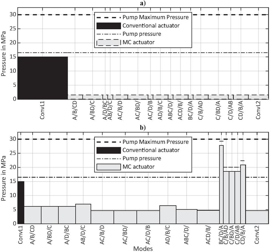
Figure 5 Proportional valve supply port flow rate vs pressure: (a) Overrunning load; (b) Non-overrunning load.
Figure 5 shows the resultant pressure and flow diagrams for the supply port of the proportional valves, calculated with Equations (1) to (6) for each of the modes. In both plots the load force on the multi-chamber actuator is 35 kN, speed is 0.2 m/s for the overrunning load and 0.2 m/s for the non-overrunning load, flow rate and pressure of the conventional actuator are m/s and 15 MPa. The width of the bars is the flow rate required from the pump and the height is the load pressure. The dash-dotted line represents the pump pressure, Equation (8). The resistive control losses can be visualized as the area between the pump pressure curve and the loads.
For the overrunning load, Figure 5(a), the pressure in the chambers connected to supply would be very small. In the calculations, they were considered to be zero but to enable the visualization, in the plot they were assigned a small value. Independent of the pressure, the pump must supply the flow rate to fill up the chambers. In such situations, the mode could be chosen to minimize the flow rate required from the pump to reduce the losses.
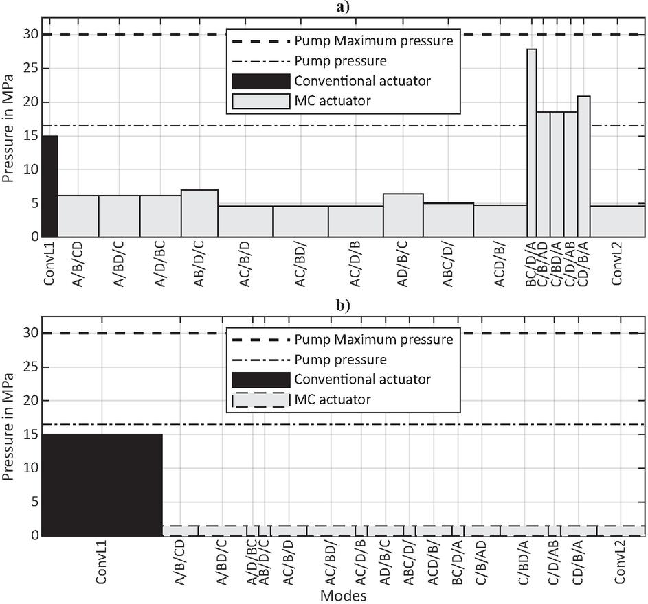
Figure 6 Proportional valve return port flow rate vs pressure: (a) Overrunning load; (b) Non-overrunning load.
Figure 5(b) shows the results for a non-overrunning load, where it is seen that certain combinations of chambers have the potential to reduce the resistive control losses. For this load, modes that result in a higher pressure and lower flow rate, like mode CD/B/A, would have an advantage over a low pressure and high flow rate mode, like A/B/CD. For higher load forces, certain modes would result in too high pressure, rendering them infeasible.
Figure 6 presents the pressure and flow diagrams for the return port of the proportional valve. For the overrunning load, Figure 6(a), the movement is controlled by the meter-out edge of the proportional valve. This diagram shows that, if one would like to recover this available energy, it would be possible also to modulate the pressure and flow rate to the energy recuperation and storage system, if available. Figure 6(b) highlights the flow rate on the return port for a non-overrunning load.
Figure 7 presents the results for the calculation of pump and resistive control power losses and the required hydraulic power according to Equations (9) to (16).
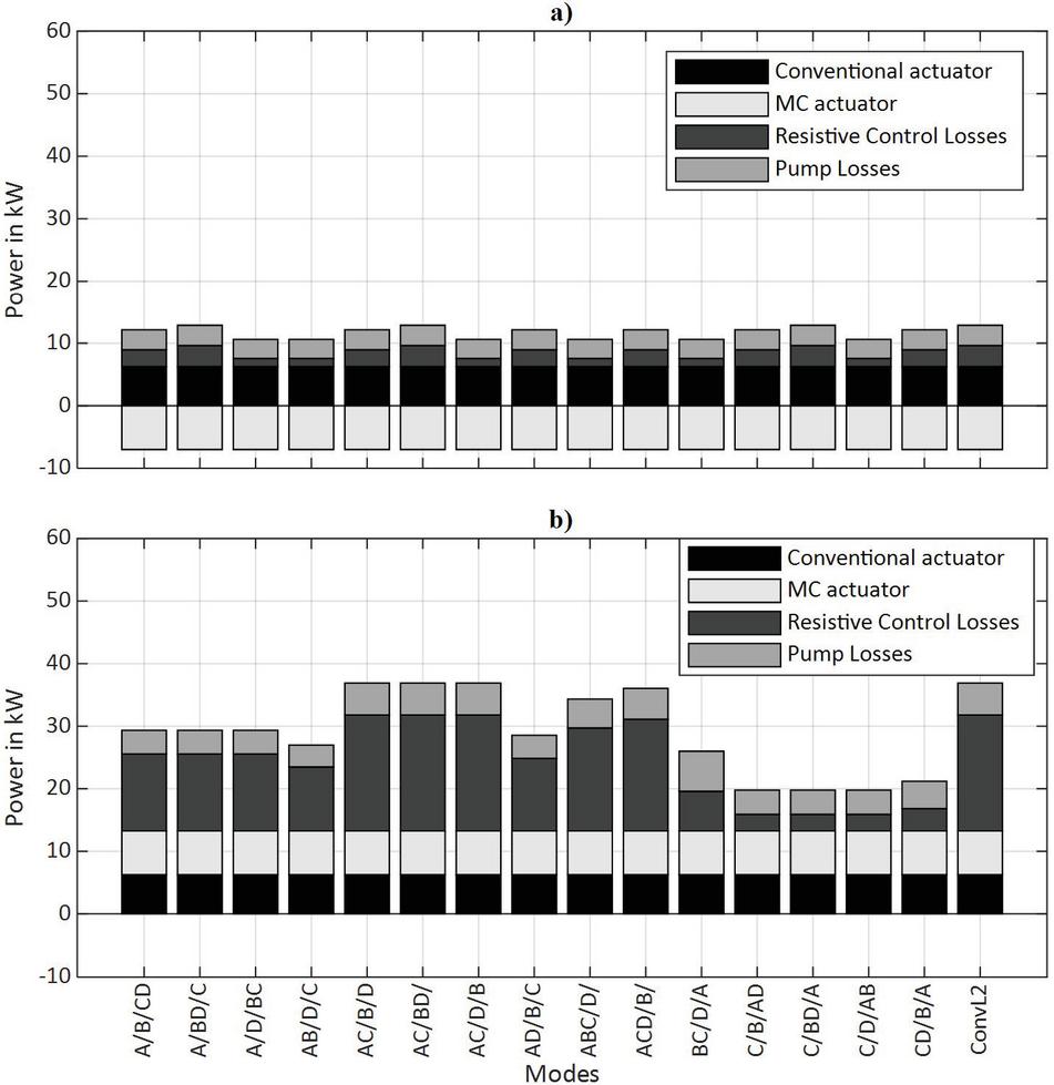
Figure 7 Power supply and power loss: (a) Overrunning load; (b) Non-overrunning load.
Figure 7(a) shows the power supplied to and lost by the system for the case of an overrunning load. The load on the multi-chamber actuator is lost when throttling the flow back to the reservoir. Although it is an overrunning load, supply losses can be affected by which mode is selected. This is because the mode affects the flow rate, which still result in resistive losses over the control valves. By selecting a mode with smaller chambers connected to supply, these losses are minimized. Although it is an overrunning load, the compensation valve must control the same pressure drop upon the proportional valve.
Figure 7(b) shows the power supplied to and lost by the system for the case of a non-overrunning load. Some modes would result in less power supplied by the system to perform the movement, like mode C/D/AB. Although the pump losses are not constant for all modes, the largest difference is caused by the reduction in resistive control losses.
Figure 8 shows the system efficiency for both conventional and multi-chamber actuators, Equation (17). It is noteworthy that most of the combinations of chambers would result in a higher efficiency than if the same load was driven by a conventional actuator with equivalent areas. In the worst-case scenario, it would have the same efficiency. It is clear the possible improvement in system efficiency with the proposed concept.

Figure 8 System efficiency: (a) Overrunning load; (b) Non-overrunning load.
It is important to mention that the friction in the actuators was not modelled. In a multi-chamber actuator it would most likely be higher. In this sense, for certain modes the system efficiency would be lower than that of the conventional system.
5.2 Range of Loads
As highlighted in the previous section, for each load there will exist a mode that results in maximum system efficiency. In this section, the maximum system efficiency is determined for a range of loads over the multi-chamber actuator. This allows the evaluation of how the mode selection would change with the change in load. The load force and speed of the Load 2 actuator span 0 to 100 kN and 0 to 0.2 m/s respectively, while they remain the same for the conventional actuator, as in Section 5.1.
Figure 9(a) shows the system efficiency, Equation (17), considering a multi-chamber actuator. For each data point it is also indicated which mode, according to Table 5, maximize the efficiency. It must be noticed that for modes that result in the same system efficiency, as presented in Figure 8, only one of them is indicated. Modes that resulted in pressures above the maximum pump pressure were removed.
The maximum efficiency remains relatively high, around 0.5 to 0.8, for the whole range presented in Figure 9(a). Despite having 16 modes to choose from, only a few of them were necessary to cover the load range with maximum efficiency. This indicates that some of the modes could be disregarded to simplify the controller. However, it is important to mention that a thinner discretization of the load range could reveal other modes that maximize the system efficiency than the ones visible in Figure 9(a). Most importantly, the load over the conventional actuator remained constant. In this sense, a more thorough investigation with other loads is necessary to be sure that some modes can be disregarded.
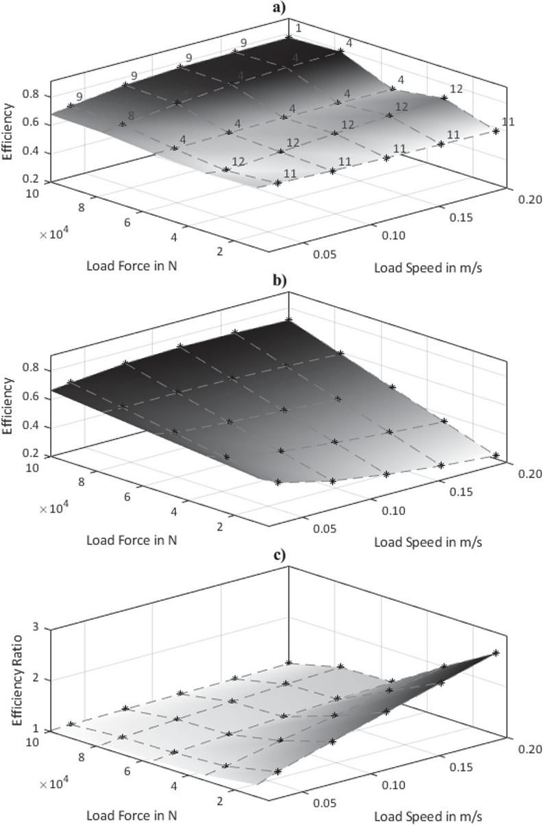
Figure 9 Range of non-overrunning loads; (a) Maximum system efficiency with multi-chamber actuator; (b) System efficiency with conventional actuator; (c) Ratio of efficiencies.
In Figure 9(a) one can notice that, for small load forces the highest efficiency is achieved with modes with smaller areas connected to the supply, since that result in higher pressure and lower flow rate. For larger forces, the modes with larger chamber areas will obviously be required to move the load.
To establish a comparison Figure 9(b) shows the system efficiency for the case of a conventional actuator moving Load 2. It is directly noticed the decrease in system efficiency for smaller load forces. The efficiency is directly impacted by the incapacity of the conventional actuator to transform the load to a range that better matches the other loads.
The difference in the efficiencies can be better visualised if they are compared directly. Figure 9(c) shows the ratio of efficiencies between the multi-chamber case and the conventional case, (). It is calculated as
| (22) |
The gain in having the capacity of adapting the load is clearly seen from Figure 9(c), where the efficiency ratio is always larger than 1, and for smaller forces and higher speeds it is significantly higher.
5.3 Compensation of Actuator Areas
For this study, mode 4 according to Table 5, is used as the reference mode area () for the determination of the compensation factor (), Equation (21). The reference mode is indicated in bold. Table 6 presents the compensation factor and the compensated valve signal () for a few input/commanded valve positions () and actuator modes. Not all modes are presented because for some of them the compensation factor ) is similar. It is also worth to mention that it was considered a 0.2 () spool overlap and maximum value of 1 (). The spool position is normalized for simplicity and the 0 to 1 input from the operator is transformed to the operating opening of the valve, 0.2 to 1.
Table 6 Valve position compensation values
| Control Edge | P to A (non-overruning) | P to B (non-overruning) | |||||||
| (Load) | or P to B (overruning) | or P to A (overruning) | |||||||
| Mode | AC/B/D | ABC/D/ | A/B/CD | AB/D/C | C/B/AD | BC/D/A | A/BD/C | A/B/CD | A/D/BC |
| 1.50 | 1.38 | 1.13 | 1.00 | 0.38 | 0.25 | 1.33 | 1.00 | 0.33 | |
| 0.20 | 0.30 | 0.28 | 0.23 | 0.20 | JK10.20 | JK10.20 | 0.27 | JK10.20 | JK10.20 |
| 0.36 | 0.54 | 0.50 | 0.41 | 0.36 | JK10.20 | JK10.20 | 0.48 | 0.36 | JK10.20 |
| 0.52 | 0.78 | 0.72 | 0.59 | 0.52 | JK10.20 | JK10.20 | 0.69 | 0.52 | JK10.20 |
| 0.68 | JK11.00 | 0.94 | 0.77 | 0.68 | 0.26 | JK10.20 | 0.91 | 0.68 | 0.23 |
| 0.84 | JK11.00 | JK11.00 | 0.95 | 0.84 | 0.32 | 0.21 | JK11.00 | 0.84 | 0.28 |
| 1.00 | JK11.00 | JK11.00 | JK11.00 | 1.00 | 0.38 | 0.25 | JK11.00 | JK11.00 | 0.33 |
Other points to consider when calculating the compensation factor are which side the valve is operating at and the load over the actuator. That determines which area of the actuator is connected to the port that is controlling the load. In this analysis we consider that an overrunning load is primarily controlled by the meter-out edge and a non-overrunning load is controlled by the meter-in edge. Although in practice this is not always true, this simplification is assumed here. In this sense the compensation factor should change according to the direction of motion and current load.
Since the areas are different in size, the compensation factors become far from 1. This results in valve saturation at or at as highlighted in grey background colour.
6 Discussion
Figure 4 shows a considerable difference between the magnitudes of flow rates at the ports of the proportional valve. This flow rate mismatch is an issue since the pressure drop in the control edges of the proportional valve would be significantly different. However, when selecting modes from the redundant ones, the larger flow rates for the different chambers can be assigned to the same ports, and the opposite is also true. The asymmetry of the proportional valve could be designed/selected to have as close a match as possible to the asymmetry of the chamber areas. A study on matching the area ratio of actuators and areas of control edges of proportional valves is presented in [11].
The ratio between the chamber areas have a significant effect on the available modes to be chosen from – on the one hand because more modes can be made feasible with respect to the discussion in Section 2. On the other hand, they could be chosen to not result in as many infeasible pressures or flow rates, e.g. when subjected to the loads common to the specific application. The choice of areas would also affect the overall efficiency of the system. This is a topic for further research, possibly by defining a design optimisation problem for the system parameters.
Table 6 showed the results of the compensation factor () to compensate the difference in areas for the different modes. This compensation should result in the same operator feeling where a certain lever command results in the same speed. However, due to the large difference in chamber areas the compensation factor leads to saturation of the valve. As for the case of number of available modes, a better design and selection of areas should reduce the saturation.
As mentioned in [12], an important feature of parallel connected systems is that no switching is needed to maintain any of the modes. Switching the valves is needed only when a different mode is desired. In this sense, the system can operate according to the load expected for a particular operation. For the entire operation, it could maintain the same actuator mode since no major load variations would exist. If the operation has larger load variations, than switching can be executed more frequently as well.
Although a multi-chamber actuator with four chambers was studied, the same concept could be applied to a three-chamber actuator. This would result in a smaller number of available modes, but likely also reduced component costs, as a consequence of having fewer on/off valves and simpler cylinder construction.
From the perspective of system complexity and cost, another interesting point is to evaluate the simplifications that could be done to the digital valve manifold. The study started with the possibility to connect each chamber to each input port (A/B/T). However, after the study it is possible to evaluate if all those connections were necessary. The valves that connect port B to chambers A and C are not necessary due to the simplifications presented in Section 2. This is seen in Table 5 where areas A and C are never connected to port B.
Another aspect that could lead to a simplification is the fact that some modes result in similar or even same efficiencies as seen in Figures 5 to 8. This would make the development of controllers much simpler. However, there are still the challenges of controlling the switching between modes to be seamless and assessing the stability of the load sensing system itself. Since they tend to be oscillating systems, the stability for each mode should be studied because the dynamic characteristics change with the mode.
7 Conclusions
This paper presented an extended analysis of a proposed concept to reduce resistive control losses of valve-controlled systems with the use of multi-chamber actuators. A case study was presented for a load sensing system with one pump driving two loads. It was shown that the different modes of the multi-chamber actuator can adapt the resultant pressure and flow rate from its load to the pressure and flow rate resultant from the load on the other actuator. In this way, resistive control losses can be significantly reduced. It is shown that modes might have similar efficiency and that only some of them might result in maximum system efficiency. It was also suggested that a smart selection of the available modes can lead to a simpler system, since the number of modes is reduced, fewer changes to the control of the proportional valve are required and simplifications could be done to digital valve manifold. It is suggested the inclusion of a compensation factor to the signal of the proportional valve to ensure similar operator feeling. Further research should be directed towards the evaluation of design parameters, the design of a controller and the evaluation of the system for more load scenarios.
Acknowledgements
This research is supported by the Brazilian Coordination for the Improvement of Higher Education Personnel (CAPES), the Brazilian National Council for Scientific and Technological Development (CNPq) and the Swedish Energy Agency (Energimyndigheten) Grant Number P49119-1.
Nomenclature
| Designation | Denotation | Value | Unit |
| Multi-c. actuator speed | – | ||
| Multi-c. actuator load | – | ||
| Conv. actuator prop. valve load pressure | – | ||
| Conv. actuator prop. valve flow rate | – | ||
| Conv. Actuator hydraulic power | – | ||
| Pump pressure | – | ||
| Pump flow rate | – | ||
| Pump hydraulic power | – | ||
| Pump power | – | ||
| Pump volumetric efficiency | – | – | |
| Pump mechanical efficiency | – | – | |
| System efficiency | – | – | |
| Ratio of efficiencies | – | – | |
| Control loss power | – | ||
| Pump power losses | – | ||
| Load sensing pressure differential | 1.5e6 | ||
| Multi-c. act. prop. valve supply flow rate | – | ||
| Multi-c. act. prop. valve pressure of the port connected to supply | – | ||
| Multi-c. act. hydraulic power | – | ||
| Multi-c. act. prop. valve return flow rate | – | ||
| Multi-c. act. prop. valve pressure of the port connected to return | – | ||
| Multi-c. act. prop. valve port A flow rate | – | ||
| Multi-c. act. prop. valve port A pressure | – | ||
| Multi-c. act. prop. valve port B flow rate | – | ||
| Multi-c. act. prop. valve port B pressure | – | ||
| Multi-c. act. port T flow rate | – | ||
| Multi-c. act. port T pressure | 0 | ||
| Multi-c. act. port A flow rate | – | ||
| Multi-c. act. port B flow rate | – | ||
| Multi-c. act. port C flow rate | – | ||
| Multi-c. act. port D flow rate | – | ||
| Multi-c. act. chambers areas | [27 3 9 1] | ||
| ] | |||
| Multi-c. act. chamber D area | 2.097e-4 | ||
| Combined areas connect to prop. valve ports | – | ||
| Uncompensated proportional valve position | – | ||
| Compensated proportional valve position | – | ||
| Pressure drop over the proportional valve | – | ||
| Oil density | – | ||
| Proportional valve compensation signal | – | – | |
| Multi-c. actuator area controlling the load | – | ||
| Multi-c. actuator reference area | – | ||
| Proportional valve flow coefficient | – | – | |
| Proportional valve spool circumference | – |
References
[1] H. Raduenz, L. Ericson, K. Heybroek, V. J. De Negri, P. Krus, ‘Improving the efficiency of valve-controlled systems by using multi-chamber actuators’. In: The 17th Scandinavian International Conference on Fluid Power, pp. 224–236, Linköping, Sweden, 2021. DOI: 10.3384/ecp182; ISBN: 978-91-7929-013-9.
[2] D. Berglund and N. Larsson, ‘Controlling a Hydraulic System using Reinforcement Learning: Implementation and validation of a DQN-agent on a hydraulic multi-chamber cylinder system’. Dissertation, Linköping University, 2021.
[3] M. Linjama, H-P. Vihtanen, A. Sipola, M. Vilenius, ‘Secondary controlled multi-chamber hydraulic actuator’. In: The 11th Scandinavian International Conference on Fluid Power, Linköping, Sweden, 2009. ISBN: 978-91-7393-588-3
[4] M. Huova, A. Laamanen, M. Linjama, ‘Energy efficiency of three-chamber cylinder with digital valve system’, International Journal of Fluid Power 11.3, pp. 15–22, 2010. DOI: 10.1080/14399776.2010.10781011
[5] A. Dell’Amico, M. Carlsson, E. Norlin, M. Sethson, ‘Investigation of a digital hydraulic actuation system on an excavator arm’. The 13th Scandinavian International Conference on Fluid Power, pp. 505–511, Linköping, Sweden, 2013. DOI: 10.3384/ecp1392a50
[6] H. C. Belan, C. C. Locateli, B. Lantto, P. Krus, V. J. De Negri, ‘Digital secondary control architecture for aircraft application’. In: The 7th Workshop on Digital Fluid Power, pp. 21–39, Linz, Austria, 2015.
[7] E. Heemskerk, R. Bonefeld, H. Buschmann, ‘Control of a semi-binary hydraulic four-chamber actuator’. In: The 14th Scandinavian International Conference on Fluid Power, Tampere, Finland, 2015. ISBN 978-952-15-3530-7
[8] K. Heybroek, J. Sjöberg, ‘Model predictive control of a hydraulic multichamber actuator; A feasibility study’. In: IEEE/ASME Transactions on Mechatronics, Vol. 23, No. 3, pp. 1393–1403, June 2018. DOI: 10.1109/TMECH.2018.2823695
[9] K. Pettersson, K. Heybroek, P. Mattsson, P. Krus, ‘A novel hydromechanical hybrid motion system for construction machines’. In: International Journal of Fluid Power, Vol. 18, Issue 1, pp. 17–28, 2017. DOI: 10.1080/14399776.2016.1210
[10] K. Heybroek, M. Sahlman, ‘A hydraulic hybrid excavator based on multi-chamber actuators and secondary control – design and experimental validation’. In: International Journal of Fluid Power, Vol. 19, Issue 2, 2018. DOI: 10.1080/14399776.2016.1210423
[11] M. C. Destro, V. J. De Negri, ‘Method for combining valves with symmetric and asymmetric actuators for hydraulic systems’. In: International Journal of Fluid Power. Vol. 19, pp. 1–14, 2018. DOI: 10.1080/14399776.2018.1483164
[12] M. Linjama, ‘Digital fluid power – state of the art’. In: The 12th Scandinavian International Conference on Fluid Power, Tampere, Finland, 2011. ISBN 978-952-15-3273-3
Biographies

Henrique Raduenz received the master’s degree in Mechanical Engineering at the Federal University of Santa Catarina (UFSC), Brazil, in 2018. Currently he is doing his double-degree doctoral studies at UFSC and at Linköping University, Sweden. The main topic of research is fluid power systems for mobile machines.

Liselott Ericson received a Ph.D in hydraulics at Linköping University (LiU), Sweden, in 2012. She currently works as an associate professor at Fluid and Mechatronic Systems at LiU. The areas of interest include pump and motor design, electro-hydraulic systems, modelling and simulation.

Kim Heybroek was born in Västervik, Sweden, in 1981. He received the M.Sc. degree in mechanical engineering from Linköping University (LiU), Linköping, Sweden, in 2006. In 2008, he joined Volvo Construction Equipment in Eskilstuna, where he is currently working as a Research Engineer and has a Specialist role in the field of hydraulics. In 2017, he received the Ph.D. degree in hydraulics at the Department of Fluid Power and Mechatronic Systems (FluMeS) at LiU.

Victor J. De Negri has been Head of the Laboratory of Hydraulic and Pneumatic Systems (LASHIP) at the Department of Mechanical Engineering, Federal University of Santa Catarina (UFSC), Brazil, since 1995. He received his D. Eng. degree in 1996 from UFSC. He is a member of ASME and ABCM and Associate Editor of the IJFP and JBSMSE. His research areas include the analysis and design of hydraulic and pneumatic systems and design methodology for mechatronic systems.

Petter Krus is a professor and head of division of Fluid and Mechatronic Systems at Linköping University in Sweden. He is also holder of the Swedish Endowed Chair in Aeronautics at “Instituto Technólogico Aeronáutica”, ITA in Brazil. His field of research is in fluid power systems, aeronautics, systems engineering, modelling and simulation and design optimisation.
International Journal of Fluid Power, Vol. 23_1, 79–108.
doi: 10.13052/ijfp1439-9776.2314
© 2021 River Publishers