Loss Calculation and Thermal Analysis of High-speed Magnetic Suspension Amorphous Motor
Xiaolu Hu1, Guibing Shi1, Yifan Lai1, Li Wang1, 2 and Juntao Yu1, 2,*
1School of Mechanical, Electrical & Information Engineering, Shandong University, Weihai 264209, China
2Weihai Institute of Industrial Technology, Shandong University, WenhuaXilu 180, 264209 Weihai, P.R. China
E-mail: juntaoyu@sdu.edu.cn
*Corresponding Author
Received 30 March 2022; Accepted 12 May 2022; Publication 12 June 2023
Abstract
High loss density, small volume and difficulty heat dissipation become important factors restricting the development of high-speed motor. In this paper, a new type of high-speed magnetic suspension amorphous motor was studied and its loss and temperature rise were analysed. The influence of cooling fan on air friction loss and cooling effect under different working conditions was studied through fluid analysis. The advantages of magnetic suspension amorphous motor were verified by analysing temperature distribution and efficiency under different conditions. The accuracy of the simulation results was verified by building an experimental platform to test the temperature of the prototype. It is showed that the application of new materials and new technologies is of great significance to improve the efficiency and stability of traditional motors.
Keywords: Magnetic suspension amorphous motor, thermal analysis, loss calculation.
1 Introduction
Permanent magnet synchronous motor (PMSM) is widely used because it eliminates intermediate growth links such as gear boxes and can realize direct drive, which greatly improves working efficiency [1]. However, the temperature rise generated under high loss density will seriously affect the stable operation of the motor due to its high power density. Therefore, the problem of PMSM loss and temperature rise has become the research hotspot of the majority of scholars in recent years.
The electromagnetic loss generated during the operation of the motor is transformed into heat energy and diffuses outwards, becoming the main heat source of the motor. The flux density of silicon steel (SS) stator core is characterized by high frequency, so the iron loss (P) will be very obvious at high speed and high working frequency [2]. So, amorphous alloy (AA) materials have attracted extensive attention because of their excellent soft magnetic properties. The stator core of motor is compared with AA and SS respectively, including loss and thermal performance under no-load and no-load conditions [3–5]. Rotor eddy current losses (P) are mainly caused by space harmonics, time harmonics of winding armature magnetic field and air gap reluctance changes caused by stator slotting [6]. For high-speed magnetic suspension motors, the rotor does not contact the rest of the machine, and the heat generated by the losses will accumulate inside the motor, which will lead to irreversible demagnetization of permanent magnets. In addition to electromagnetic loss, air friction loss (P) is also an important part of the high-speed motor, becoming an important factor affecting the temperature rise of the motor [8]. Therefore, accurate calculation of loss is the basis of motor temperature rise analysis.
In this paper, a 35 kW, 30 krpm magnetic suspension amorphous motor developed in the laboratory was studied, and its loss and temperature rise were analysed by electromagnetic-thermal-fluid (ETF) coupling method. The research of electromagnetic field includes P, copper loss (P) and P, which mainly analysed the influence factors of stator P and permanent magnet P. Through the flow field analysis, the influence of different cooling air speed and rotation speed on P was studied, so that a reasonable method was taken to effectively cool the motor. Finally, an experimental platform was built to test the temperature rise of the prototype. The accuracy of the ETF coupling analysis method and the high efficiency of high-speed magnetic suspension amorphous motor were verified. This was of great significance for the loss reduction, accurate prediction of high-speed PMSM temperature rise during the design stage and the development of high efficiency and energy saving motor.
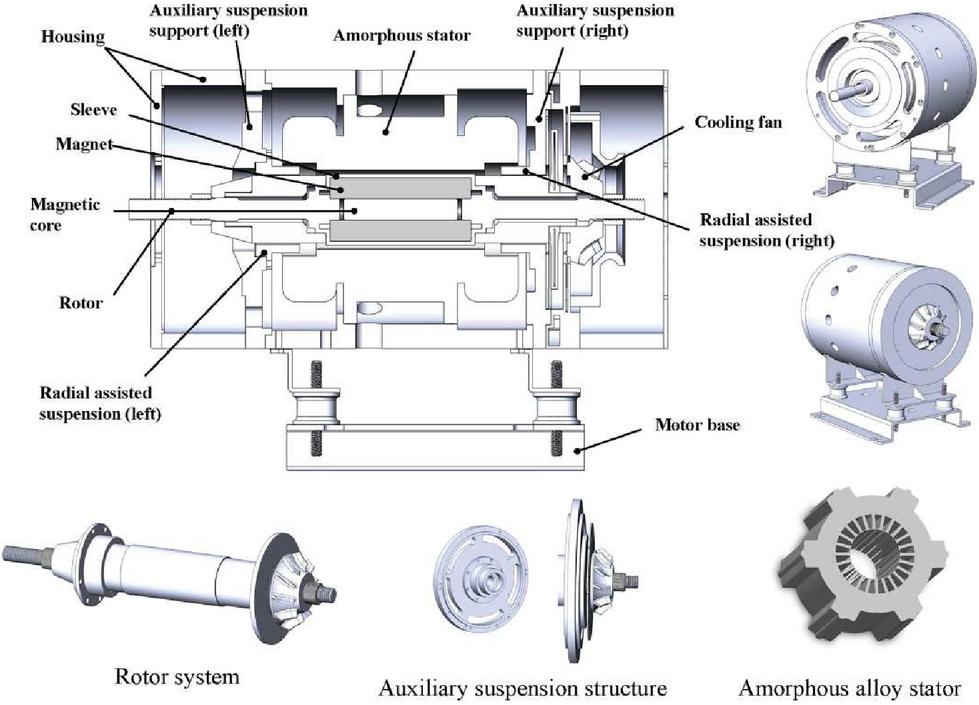
Figure 1 Motor structure model.
2 Motor Structure Model
In this paper, a bearingless magnetic suspension amorphous motor was designed. The active suspension control was realized by stator winding and permanent magnet rotation, and no additional magnetic bearings were required. Therefore, a smaller rotor size and a higher critical speed were achieved. The rotor adopts sleeve structure to ensure that the permanent magnet was not damaged under high speed working intensity. The use of amorphous alloy as stator core material, can significantly reduced the loss of motor at high speed and high frequency. In addition, due to the large air gap width of magnetic suspension motor, forced air cooling was carried out on it, and a circle of cooling holes was set on the outer surface of the shell to avoid the complex structure brought by water cooling. The structure of magnetic suspension amorphous PMSM used in this paper is shown in Figure 1, and the basic design parameters are shown in Table 1.
Table 1 Motor structure parameters
| Parameters | Value | Parameters | Value |
| Rated power/kW | 37.5 | Stator outer diameter/mm | 139 |
| Rated speed/rpm | 30000 | Stator inter diameter/mm | 58.85 |
| Rated voltage/V | 380 | Rotor outer diameter/mm | 53 |
| Winding layer | single | Rotor inter diameter/mm | 22 |
| Slot number | 24 | Poles number | 2 |
3 Electromagnetic Analysis
3.1 Iron Loss
The classical iron loss theory of Bertotti clearly introduces the mechanism of P, which can be divided into hysteresis loss (P), eddy current loss (P) and additional loss (P) [9]. The specific calculation formula can be expressed as:
| (1) |
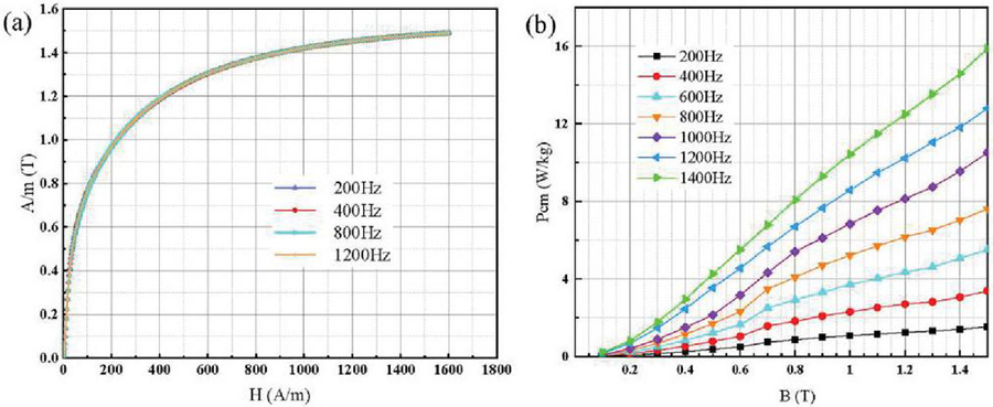
Figure 2 (a) Magnetization curve and (b) Loss density.
Where , and is hysteresis loss factor, eddy current loss factor and additional eddy current loss factor, respectively. f is the magnetic field frequency, and B is flux density.
Due to the characteristics of small coercivity, low remanence and low resistivity of AA, the P and P are much smaller than those of SS stator [3]. The magnetization curve and loss density of the AA stator used in this paper at different frequencies are shown in Figure 2. The material properties are imported into Maxwell to obtain the loss of stator core under different working conditions. Figure 3 shows that the P of the SS stator is much higher than that of AA stator. Under load, the average iron loss of the SS stator is 580 W, while that of AA stator is 190 W. The loss of the AA as the motor stator core is reduced by nearly 70% at high frequency.
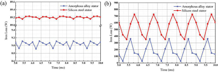
Figure 3 Loss comparison between AA stator and SS stator: (a) Stator iron loss at no-load; (b) Stator iron loss at on-load.
3.2 Copper Loss
The size of winding P directly affects the performance of the motor and temperature rise because it is one of the main losses of motor. With the increase of frequency, the skin effect and proximity effect of stator windings became obvious, and the alternating current P of stator windings also increased. Without considering the change of resistance, the P is calculated by analytical method [10]:
| (2) |
where m is the number of phases, I is the current through the winding and R is the resistance.
In order to improve the efficiency of thermal analysis and simplify the winding equivalently, the results of electromagnetic field analysis had some errors, so the empirical formula was used to calculate P. P distribution at different speeds is shown in Figure 4.
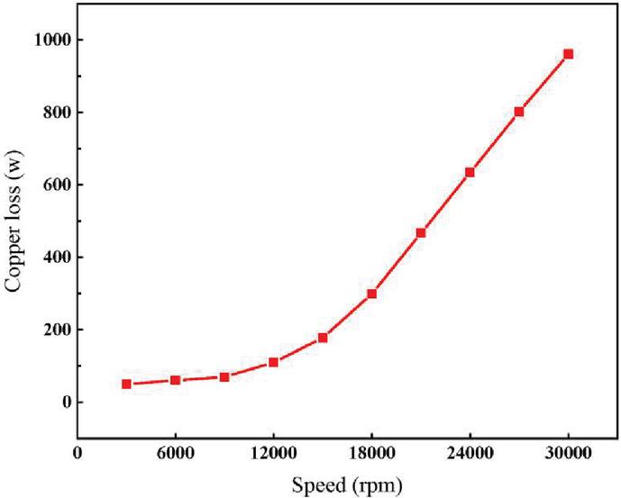
Figure 4 Copper loss distribution at different speeds.
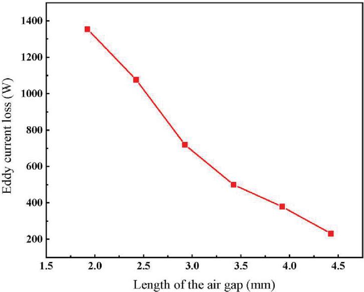
Figure 5 Effect of different air gap lengths on eddy current losses.
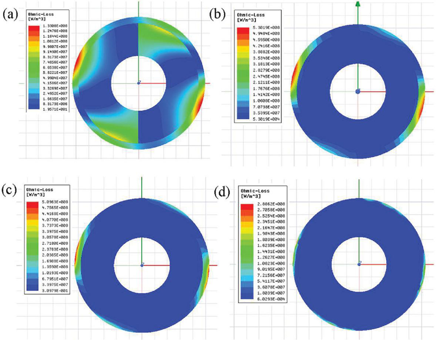
Figure 6 P distribution of different sleeve materials: (a) Carbon fiber sleeve; (b) Titanium alloy sleeve; (c) Zinc alloy sleeve and (d) Titanium alloy sleeve and copper shield.
3.3 Eddy Current Loss
P of permanent magnet is affected by spatial harmonics of magnetic field, which can be reflected by the change of air gap length [11]. In this paper, the thickness of the permanent magnet was adjusted accordingly while the length of the air gap was changed to ensure that the magnetic field intensity in the middle of the air gap basically unchanged. Figure 5 shows the changes of rotor P under different air gap lengths. The results show that the P decreased significantly with the increase of air gap length. The air gap length increased from 1.9 mm to 4.4 mm, and the P decreased by about 68%. However, when the air gap length was larger than 3.92 mm, the amount of permanent magnets increased significantly, but the P did not decrease effectively. When the air gap width was 4.4 mm, the sleeve must be completely filled with permanent magnets to ensure the constant magnetic field intensity. Therefore, various factors should be integrated when determining the length of the motor air gap, rather than the larger the more appropriate.
The sleeve not only plays the role of protecting rotor permanent magnet, but also contributes greatly to P of permanent magnet [12]. Figure 6 shows that different sleeve materials have different shielding effects on permanent magnets. Among them, carbon fiber sleeve had the worst shielding effect on permanent magnet P, while titanium alloy sleeve and copper shield can almost shield most P. The electrical conductivity of each part of the material corresponds to Figure 6. With the increase of the conductivity of the sleeve, the P in the permanent magnet body decreased all the time, while the P in the sleeve approached normal distribution with the change of conductivity. When the conductivity was less than , the induced current decreased and P decreased gradually. When the electrical conductivity is reduced to close to the insulation material, there is almost no P in the sleeve, and the harmonic field will directly act on the permanent magnet. The eddy current in the permanent magnet is very obvious, resulting in great loss. When the resistivity is greater than , as the conductivity increased, the resistance became very small and approached the superconducting material. The diamagnetic shield ring current was generated to isolate the rotor from the air gap magnetic field and played the role of magnetic shield. As a result, the P of both the sleeve and the permanent magnet are reduced. So, if the sleeve is an ideal superconductor, the magnetic shielding effect can counteract the vortices in the sheath and permanent magnet.
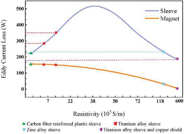
Figure 7 Effect of sleeve conductivity on eddy current loss of rotor.
4 Flow Analysis
The P generated by the motor at high speed cannot be ignored. The internal cooling channel of the motor is shown in Figure 8. While cooling the rotor, the air flow will also produce P. Pa was commonly calculated by the following analytical formula [13]:
| (3) |
where is the friction coefficient and it is related to the surface structure of the stator and rotor; is the air density; is the rotor angular velocity; r is the rotor radius and is the rotor axial length.
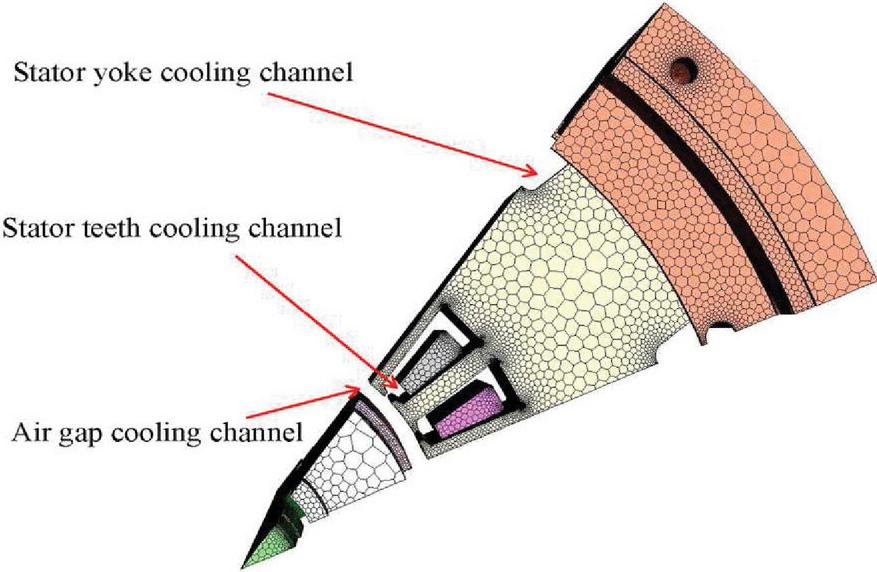
Figure 8 Cooling channels inside the motor.
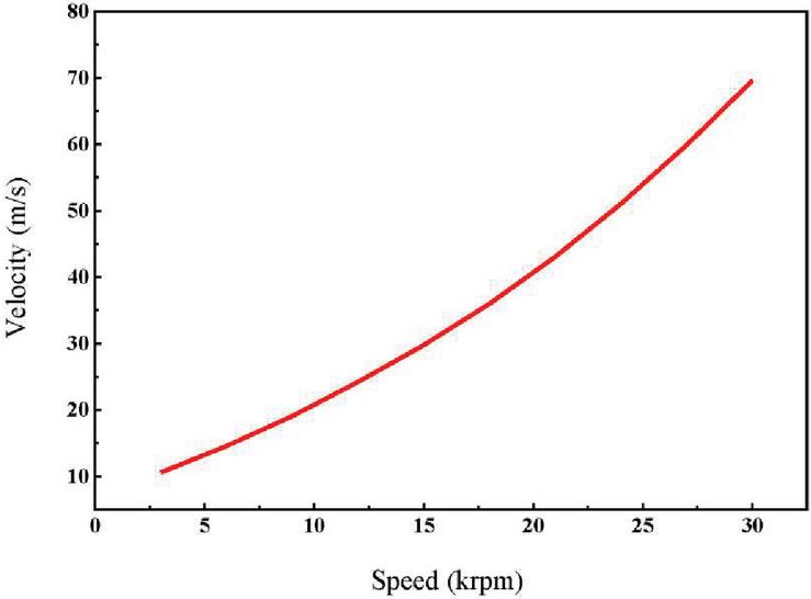
Figure 9 Cooling air speed at different speeds.
When the cooling fan rotates with the motor, it can be seen from Figure 9 that the speed increases from 3000 rpm to 30000 rpm, the maximum speed of the cooling air in the air gap increases from 10 m/s to 70 m/s, with almost exponential growth.
P in the cooling process is analysed in Figure 10. In the case of the same cooling air speed, with the increase of motor speed, the P in the machine increased gradually, and the increase gradient became larger and larger. At the same speed, when the air speed was below 40 m/s, the P was small, but the P increased by more than 3 times at high speed when the cooling air speed increases from 40 m/s to 70 m/s.
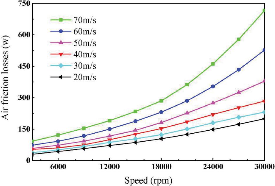
Figure 10 Air friction loss at different speed and cooling speed.
5 Coupled Temperature Field Analysis
5.1 Coupling Conditions and Process
In this paper, ANSYS-Fluent was used to analyse the temperature field, which solved the problem of non-uniform distribution of the loss, and improved the accuracy of motor temperature rise analysis through several coupling iterations. The specific realization process is shown in Figure 11. Based on the analysis of electromagnetic field and fluid field, the boundary conditions of temperature field are as follows:
(1) The cooling air inlet is set as the velocity-inlet boundary condition, and the air speed at the inlet is assumed to be 70 m/s. Outlet is set as pressure-outlet boundary conditions, outlet pressure is standard atmospheric pressure, environmental temperature is set as 25C.
(2) The amorphous stator core, winding, permanent magnet and rotor are all heat sources, wherein electromagnetic losses are directly mapped to the temperature field through Fluent.
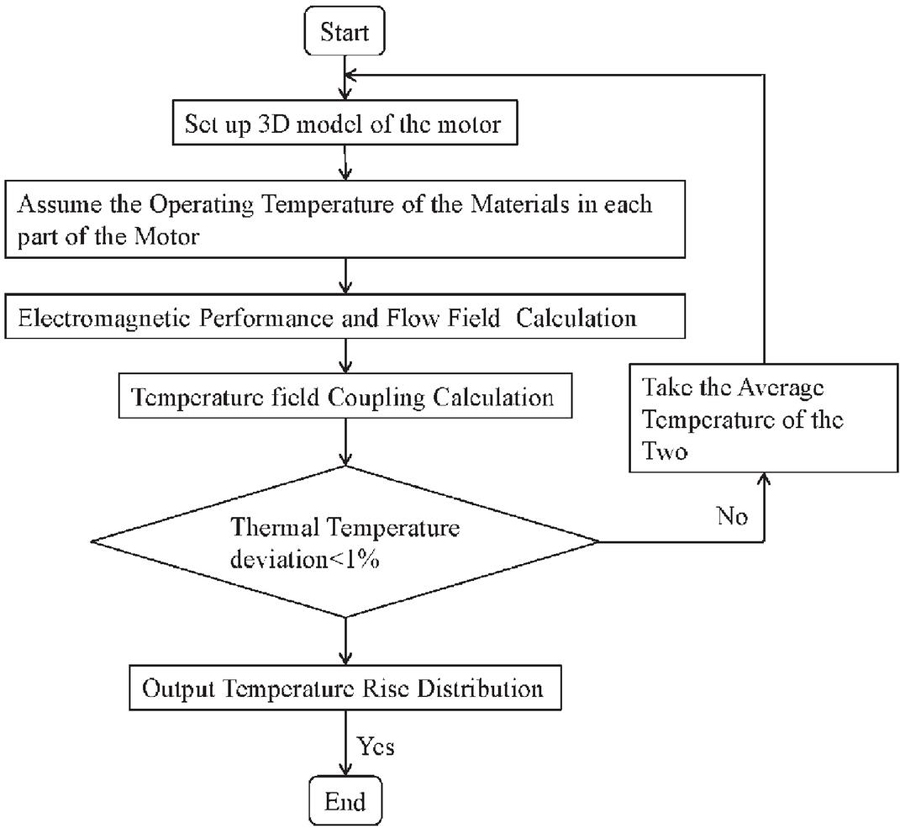
Figure 11 Coupled iterative process.
Table 2 Motor material parameters
| Density | Specific Heat | Thermal | ||
| Parameters | Materials | (kg/m) | Capacity J/(kgK) | Conductivity (W/m/K) |
| Stator | Amorphous | 7180 | 430 | 18 |
| Magnet | Ti-alloy | 4500 | 612 | 8 |
| Rotor sleeve | Sm-Co | 8300 | 500 | 23 |
| Winding | Copper | 8930 | 386 | 400 |
| Housing | Steel | 7850 | 500 | 15 |
(3) The stator and rotor air gap interface is set as the motion boundary, and the speed at the interface is the motor speed.
(4) Due to the relatively low temperature of the housing surface of the motor, the influence of radiation heat transfer is ignored. The specific parameters of materials for each motor component are shown in Table 2.
5.2 Influence of Air Gap Length on Rotor Temperature
The length of air gap plays a key role in the cooling of magnetic suspension rotor. Figure 12 shows the temperature distribution of the rotor under different air gap lengths. It can be seen that with the increase of the air gap length, the surface temperature of the rotor decreased significantly. As the air gap length increases, the P of the rotor can be effectively reduced and the heat generation reduced. In addition, it can increase the flow of cooling air and improve the heat dissipation efficiency of the rotor. Therefore, the reasonable selection of air gap length of magnetic suspension motor can significantly improve the cooling efficiency of the motor, which is of great significance to the design of rotor cooling structure of high-speed magnetic suspension motor.

Figure 12 Rotor temperature distribution with different air gap lengths: (a) 1.925 mm; (b) 2.425 mm; (c) 2.925 mm and (d) 3.425 mm.
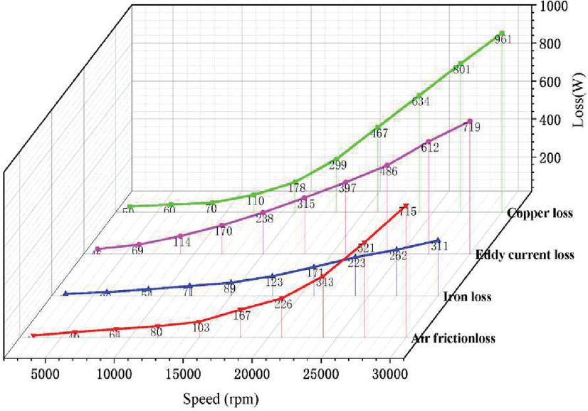
Figure 13 Loss distribution at different speeds.

Figure 14 Temperature and efficiency distribution at different speeds.
5.3 Overall Temperature Distribution of the Motor
The heat source and boundary conditions of the motor are different under different working conditions. Figure 13 shows the loss distribution at different speeds. It can be seen from Figure 14 that with the increase of speeds, the temperature rise gradient of each part gradually increases. It can be seen from Figure 15 that the main temperature rise of the motor occurs in the motor winding, and the maximum temperature of the motor is less than 115C. The highest temperature of the stator core was mainly concentrated in the stator slot, which had a high loss density and heat transfer from the winding, therefore the temperature was high. The maximum temperature of the permanent magnet was about 92C. The overall temperature was below 120C, and the temperature law of each part is within a reasonable range. The results show that it is better to use amorphous alloy as stator core and magnetic suspension rotor. Therefore, due to the reduction of loss, air cooling can be used to meet the requirements of magnetic suspension amorphous motor, without the need of complex water cooling structure.
According to the efficiency analysis in Figure 14, the overall efficiency of the motor is 96.3% at 30 krpm. The development of permanent magnet synchronous motor combining amorphous stator and bearingless magnetic suspension technology is of great significance to the development of high efficiency motor and provides a reference direction for the research and development of low loss, high efficiency and energy saving motor.
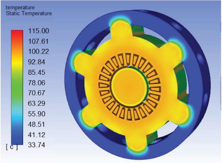
Figure 15 Temperature distribution of each part of the motor at 30 krpm.
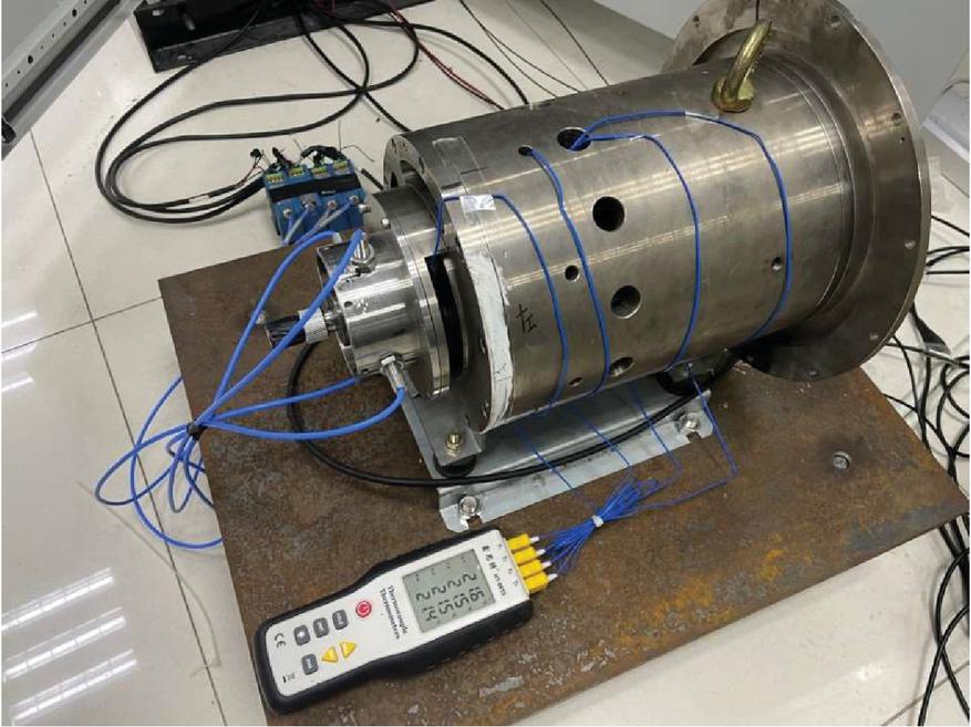
Figure 16 Temperature rise experiment platform.
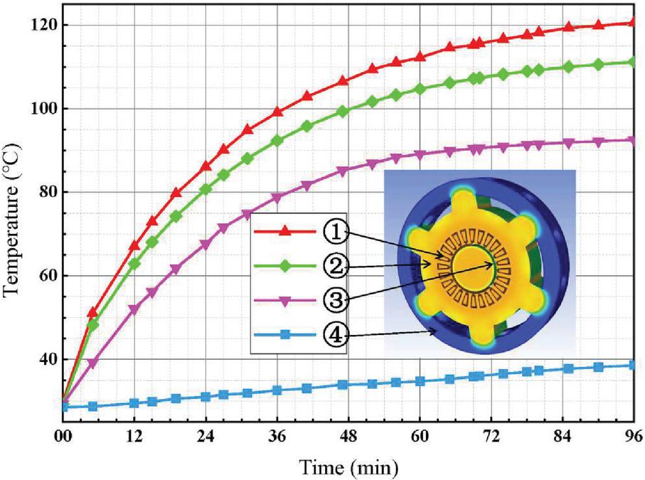
Figure 17 Motor temperature rise process at 30 krpm.
6 Temperature Rise Test
Combined with the simulation results, an experimental platform for motor temperature rise was built. During prototype manufacturing, thermal resistance temperature sensors were embedded in the winding end, stator and rotor positions for easy measurement. The test platform is shown in Figure 16. The specific test points are shown in Figure 17, mainly including winding, stator, outer surface of rotor, and housing measurement.
It can be seen from Figure 17 that the temperature rise of the motor is basically stable after running 96 minutes at 30 krpm. The winding temperature was 120C, the stator temperature was 111C, the rotor surface temperature is 90C, and the housing temperature is 38C.
As can be seen from Figure 18, there are errors between the experimental results and the simulation results. Since the temperature of the internal permanent magnet cannot be measured, only the outer surface of the rotor can be measured. The use of magnetic bearing increased the difficulty of measuring the rotor, so the rotor error became large. The winding error mainly came from the equivalent of the winding. The actual winding structure was more complex, so the measured temperature was greater than the simulation temperature. However, the above errors were within the allowed range, and the error between the overall experimental results and the simulation results was less than 10C.
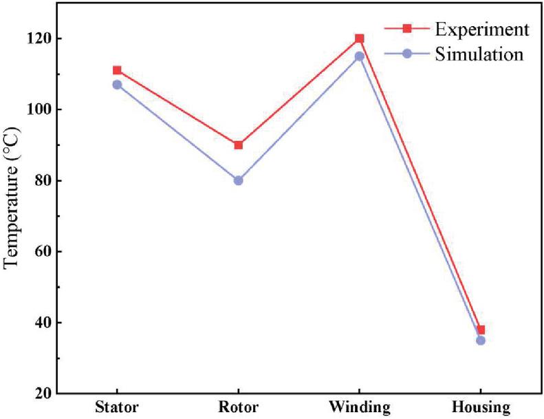
Figure 18 Comparison of simulation and experimental results.
7 Conclusion
In high-speed PMSM, loss and temperature rise are the key factors that affect the efficiency and stable operation of the motor. In this paper, the loss and temperature rise of magnetic suspension amorphous motor were analysed by ETF coupling method. The results show that the P can be reduced by 70% when AA was used as motor stator core at high speed. Proper selection of air gap length and sleeve material can effectively reduce P of permanent magnet. In addition, the increase of air gap length can improve the flow of cooling air, thus improving the heat dissipation efficiency of the motor. The experimental results were in good agreement with the simulation results. The analysis in this paper proved that the application of AA and magnetic bearing in high speed and high power PMSM can reduce the loss, and the motor efficiency can reach 96.3%. This provided a reference for the further improvement of motor efficiency and was of great significance to the development of high efficiency and energy saving motor.
Acknowledgments
Financial supports from the National Key Research and Development Program of China (No. 2021YFB3500205), the Key Research and Development Plan of Shandong Province (No. 2021CXGC010309) and Natural Science Foundation of Shandong Province (No. ZR2020ME119) are gratefully acknowledged.
Competing Interests
The authors have no relevant financial or non-financial interests to disclose.
Authors’ Contributions
Xiaolu Hu: Conceptualization, Methodology, Investigation, Writing-original draft, Writing-reviewing & editing. Guibing Shi: Methodology, Writing-reviewing & editing. Yifan Lai: Methodology, Writing-reviewing & editing. Li Wang: Conceptualization, Methodology. Juntao Yu: Writing-reviewing & editing, Project administration, Funding acquisition, Supervision.
References
[1] D. Gerada, A. Mebarki, N. L. Brown, C. Gerada, A. Cavagnino, and A. Boglietti, High-speed electrical machines: Technologies, trends, and developments, in IEEE Transactions on Industrial Electronics, vol. 61, no. 6, pp. 2946–2959, Jun. 2014. DOI: https://dx.doi.org/10.1109/TIE.2013.2286777.
[2] J. Kim, I. Jeong, K. Nam, J. Yang and T. Hwang, Sensorless Control of PMSM in a High-Speed Region Considering Iron Loss, in IEEE Transactions on Industrial Electronics, vol. 62, no. 10, pp. 6151–6159, Oct. 2015. DOI: https://dx.doi.org/10.1109/TIE.2015.2432104.
[3] W. Tong, S. Dai, S. Wu and R. Tang, Performance Comparison Between an Amorphous Metal PMSM and a Silicon Steel PMSM, in IEEE Transactions on Magnetics, vol. 55, no. 6, pp. 1–5, Jun. 2019. DOI: https://dx.doi.org/10.1109/TMAG.2019.2900531.
[4] W. Tong, R. Sun, S. Li and R. Tang, Loss and Thermal Analysis for High-Speed Amorphous Metal PMSMs Using 3-D Electromagnetic-thermal Bi-Directional Coupling, in IEEE Transactions on Energy Conversion, vol. 36, no. 4, pp. 2839–2849, Dec. 2021. DOI: https://dx.doi.org/10.1109/TEC.2021.3065336.
[5] W. Tong, R. Sun, C. Zhang, S. Wu and R. Tang, Loss and Thermal Analysis of a High-Speed Surface-Mounted PMSM With Amorphous Metal Stator Core and Titanium Alloy Rotor Sleeve, in IEEE Transactions on Magnetics, vol. 55, no. 6, pp. 1–4, Jun. 2019. DOI: https://dx.doi.org/10.1109/TMAG.2019.2897141.
[6] B. Dong, K. Wang, B. Han, S. Zheng, Thermal Analysis and Experimental Validation of a 30 kW 60000 r/min High-Speed Permanent Magnet Motor With Magnetic Bearings, in IEEE Access, vol. 7, pp. 92184–92192, July. 2019. DOI: https://dx.doi.org/10.1109/ACCESS.2019.2927464.
[7] Z. Huang, J. Fang, X. Liu, B. Han, Loss Calculation and Thermal Analysis of Rotors Supported by Active Magnetic Bearings for High-Speed Permanent-Magnet Electrical Machines, in IEEE Transactions on Industrial Electronics, vol. 63, no. 4, pp. 2027–2035, April. 2015. DOI: https://dx.doi.org/10.1109/TIE.2015.2500188.
[8] Y. Hu, B. Chen, J. Jia, X. Zhang, J. Liu and Z. Li, Design and Analysis of Cooling System for High Speed PM Synchronous Motor with Magnetic Bearings, in 2018 21st International Conference on Electrical Machines and Systems (ICEMS), pp. 228–233, Nove. 2018. DOI: https://dx.doi.org/10.23919/ICEMS.2018.8549036.
[9] G. Bertotti, General properties of power losses in soft ferromagnetic materials, in IEEE Transactions on Magnetics, vol. 24, no. 1, pp. 621–630, Jan. 1988. DOI: https://dx.doi.org/10.1109/20.43994.
[10] Y. Tang, L. Chen, F. Chai and T. Chen, Thermal Modeling and Analysis of Active and End Windings of Enclosed Permanent-Magnet Synchronous In-Wheel Motor Based on Multi-Block Method, in IEEE Transactions on Energy Conversion, vol. 35, no. 1, pp. 85–94, March. 2020. DOI: https://ieeexplore.ieee.org/document/8863503.
[11] Y. Xia, G. Li, Z. Qian, Q. Ye and Z. Zhang, Research on rotor magnet loss in fractional-slot concentrated-windings permanent magnet motor, 2016 IEEE 11th Conference on Industrial Electronics and Applications (ICIEA), 2016, pp. 1616–1620. DOI: https://dx.doi.org/10.1109/ICIEA.2016.7603844.
[12] N. Boubakera, D. Matta, P. Enricia, F. Nierlichb, G. Durandb, F. Orlandinic, X. Longèrec, J.S. Aïgbac, Study of eddy-current loss in the sleeves and Sm-Co magnets of a high-performance SMPM synchronous machine (10 kRPM, 60 kW), in Electric Power Systems Research, vol. 142, pp. 20–28, Jan. 2017. DOI: https://doi.org/10.1016/j.epsr.2016.08.045.
[13] Y. Zhang, S. McLoone, W. Cao, F. Qiu and C. Gerada, Power Loss and Thermal Analysis of a MW High-Speed Permanent Magnet Synchronous Machine, in IEEE Transactions on Energy Conversion, vol. 32, no. 4, pp. 1468–1478, Dec. 2017. DOI: https://dx.doi.org/10.1109/TEC.2017.2710159.
Biographies

Xiaolu Hu was born in Zhangjiakou, Hebei, China, in 1996. She received the B.S. degree in metallurgical Engineering from North China University of Science and Technology, Tangshan, China, in 2019. She is currently pursuing the M.S. degree in materials science and engineering at Shandong University, Weihai, Shandong, China.
Her current research interest includes heat dissipation and cooling optimization design of high speed magnetic suspension amorphous motor.

Guibing Shi was born in Shanxi, China, in 1995. He received his M.S. degree in materials Science and Engineering from Beijing General Research Institute for Non-Ferrous Metals, Beijing, China, in 2020. Mainly engaged in the field of rare earth permanent magnet material research. He is currently pursuing his Ph.D in mechanical engineering at Shandong University, Weihai, Shandong, China.
His current research interests include the research of amorphous nanocrystalline soft magnetic composites and device design.

Yifan Lai was born in Chengdu, Sichuan, in 1998. She received the B.S. degree in Material Molding & Controlling Engineering from Shandong University, Jinan, China, in 2020. She is currently pursuing the M.S. degree in Materials and Chemicals at Shandong University, Weihai, Shandong, China.
Her current research interests include processing technologies of amorphous iron cores and properties of amorphous motors.

Li Wang was born in Weihai, Shandong, in 1973. She received her M.S. degree and Ph.D. degree in materials processing engineering from Shandong University, Jinan, China, in 1998 and 2001, respectively. Currently.
She is the executive Vice President of The School of Mechatronics and Information Engineering, Shandong University, Weihai, Shandong. Her research interests are new-generation magnetic materials and electromagnetic drive control.

Juntao Yu was born in Weihai, Shandong, in 1982. He received his M.S. degree and Ph.D. degree in Mechatronics engineering from Beihang University, Beijing, China, in 2005 and 2013, respectively.
He is presently working as a lecturer in School of Mechanical and Electrical Engineering, Shandong University, Weihai, Shandong, China. His research direction is design, simulation and debugging of electro-hydraulic servo system and components.
International Journal of Fluid Power, Vol. 24_3, 419–440.
doi: 10.13052/ijfp1439-9776.2431
© 2023 River Publishers