Fault Analysis and Diagnosis of Downhole Traction Robot Hydraulic System
Delei Fang1,*, Yong Xue2, Guofeng Jia1, Pan Li1, Jie Tang3 and Xiaoming Wang1
1Tianjin Key Laboratory of Integrated Design and On-line Monitoring for Light Industry & Food Machinery and Equipment, College of Mechanical Engineering, Tianjin University of Science & Technology, Tianjin 300222, China
2Beijing Special Engineering Design Institution, Beijing, 100028, China
3Aviation Engineering Institute, Civil Aviation University of China, Tianjin, 300300, China
E-mail: fangdelei@tust.edu.cn
*Corresponding Author
Received 08 April 2022; Accepted 07 August 2022; Publication 12 June 2023
Abstract
Fault diagnosis of downhole traction robot has characteristics of special mechanical structure, complicated working condition and lack of research data. In this paper, a method of fault analysis and diagnosis of tractor hydraulic system based on model is presented. The failure mode and mechanism of key components in telescopic hydraulic system are analyzed. The fault diagnosis of hydraulic system is proposed based on the mathematical model of hydraulic component. Based on AMESim, the fault model of hydraulic system is established, and the diagnosis of single fault and multi-fault are simulated, which can collect the fault data and the specific diagnosis process. To carry forward the engineering application, the simulated internal leakage system in cylinder is set up and schemes of fault diagnosis are carried out, which prove that the diagnosis is consistent with theoretical analysis and simulation. The research on fault analysis and diagnosis of the downhole traction robot hydraulic system not only lays theoretical basis for the tractor fault detection, but also provides guidance for the construction and implementation of the diagnostic system.
Keywords: Fault analysis and diagnosis, downhole traction robot, hydraulic system, mathematical model.
1 Introduction
With the development of horizontal well technology, downhole traction robot has been widely used in drilling, logging and other underground operations [1–3]. Durability and reliability in tractor operations are increasingly challenging, because of high temperature and high pressure environment. Therefore, it is significant to ensure that downhole tractor works normally and stably in extremely complex environments [4–6].
Downhole traction robot has a limited number and complex structure, its reliability is a typical small sample and multi-stage problem, which cannot be evaluated by traditional large sample statistical tests. So, the fault diagnosis for downhole robot should be researched from the point of fault mechanism, which is based on the mathematical model of each component. Also, in this way, a large number of failure data can be collected to provide the basis for the further fault diagnosis. The existing fault diagnosis and methods of traditional hydraulic equipment can provide a good reference for the fault diagnosis of tractor hydraulic system [7–10]. Chen studied the influence in the sizes of overflow valve damping hole on pressure overshoot, transition time and adjusting pressure. Also, some researches on fault injection for machinery hydraulic system are also widely carried out based on the simulation software [11–13]. Zhou carried out a simulation research on hydraulic system leakage based on AMESim, which can be used to judge the location and cause of leakage fault [14]. Zhang analyzes the causes of leakage in the piston pump by taking the eccentric annular gap of the piston pair as the research object. By changing the size of the annular gap, the pressure and flow are simulated, to realize the injection of internal leakage fault [15]. Chen simulated the common fault conditions and collect sample data based on AMESim software, and the BP neural network was applied for fault simulation training and diagnosis test [16].
In this paper, the structure of downhole traction robot and its working principle and operation features are introduced. The telescopic hydraulic system is selected as the research object, and mathematic models for some key components are established based on the analysis of failure mechanism. Through the application of AMESim, the typical fault models and simulation system can be built to verify the feasibility of fault diagnosis. Finally, in order to verify the practical effect of the fault diagnosis, the experimental system of internal leakage in telescopic cylinder is built, and some trials will be carried out for rapid diagnostic test.
2 Mathematical Model
2.1 Description of Hydraulic System
Figure 1 shows the prototype of downhole traction robot based on one-way locking mechanism. The tractor consists of mechanical structure including two locking mechanisms and one telescopic mechanism, hydraulic system and the controller integrated in the body. The tractor movement is realized by alternating locking between the both locking mechanisms and the expansion of telescopic mechanism.
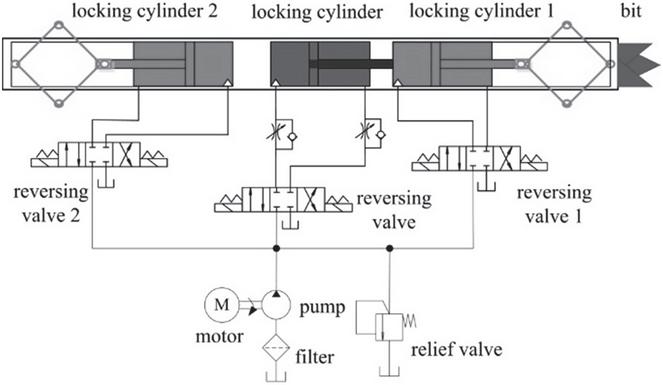
Figure 1 Diagram of downhole traction robot system.
There are some key components in hydraulic system, including asymmetric hydraulic cylinder which can realize locking and expanding, reversing valve which controls the motion direction of hydraulic cylinder, speed control valve which is responsible for the moving speed, motor and hydraulic pump which provide energy for the whole machine. Because of modular design and similar configuration, hydraulic system in telescopic mechanism is selected as the object for fault analysis and diagnosis, and the research methods can be applied to the downhole traction robot for the other fault diagnosis.
2.2 Mathematical Model
It is known in previous operations that hydraulic cylinder, speed control valve and reversing valve have a high frequency of failure. Therefore, some typical faults in the three components are analyzed. The corresponding mathematical models are established below.
2.2.1 Model of hydraulic cylinder
In hydraulic cylinder, the most typical fault is leakage, which is caused by a broken seal. Due to the fluid flow between both cylinder cavities, the leakage usually affects the motion of cylinder piston. In the telescopic mechanism hydraulic system, the schematic diagram of cylinder is shown in Figure 2.
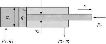
Figure 2 Schematic diagram of telescopic hydraulic cylinder.
Combined with cylinder speed, pressure, the flow equation can be expressed as:
| (1) |
where, and are the areas of big cavity and rod cavity, respectively, and are the pressures of the both cavities. is the displacement, , are the volumes of the two cavities, is the bulk elastic modulus of the fluid.
When cylinder is leaking, the flow equation above is expressed as follow,
| (2) |
where, is the internal leakage.
When working pressure is steady, the formula of internal leakage is obtained.
| (3) |
Therefore, deviation estimator can be used to detect the leakage in cylinder.
| (4) |
2.2.2 Model of speed control valve
In hydraulic system of downhole robot, the structure of speed control valve is shown in Figure 3. Because drilling fluid is the transmission medium with many solid particles, speed valve is prone to blockage. Figure 3(b) shows simplified model of speed control valve.
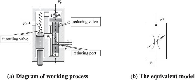
Figure 3 The structure diagram of speed control valve.
The flow expression in reducing valve is obtained.
| (5) |
where, is the flow through reducing valve, is the flow coefficient, is the area gradient. is the opening of the valve port. is the input pressure. is the output pressure.
The flow expression in throttling valve is obtained.
| (6) |
where, is the flow through the throttle valve. is the flow coefficient, is the area gradient. is the opening of the valve port. is the output pressure.
Ignoring the friction between the spool and valve body, force balance on reducing valve spool can be expressed.
| (7) |
where, is the spring stiffness, is the pre-compression of spring; is the effective area on spool. is the stable hydraulic force.
| (8) |
Combining Equations (5), (6), (7) and (8), flow expression in the speed control valve is got as follow.
For a specific speed control valve, the offset of the reducing valve spool is far less than the pre-compression of the spring, , so can be expressed as .
The fault in the speed control valve changes the value opening y and effect the steady flow. So, the difference between the theoretical flow and the actual flow can be used as the deviation estimator to detect the blockage failure.
| (10) |
2.2.3 Model of reversing valve
According to the actual operation, the main faults of reversing valve include the insufficiency of spool opening and internal leakage Schematic diagram of the reversing valve in the telescopic hydraulic system is shown in Figure 4. Port P is the high pressure port, and port T is the low pressure port. Port A and port B connect the two cavities respectively. Figure 4(b) is the diagram of computational model, which is used to establish the mathematical model.
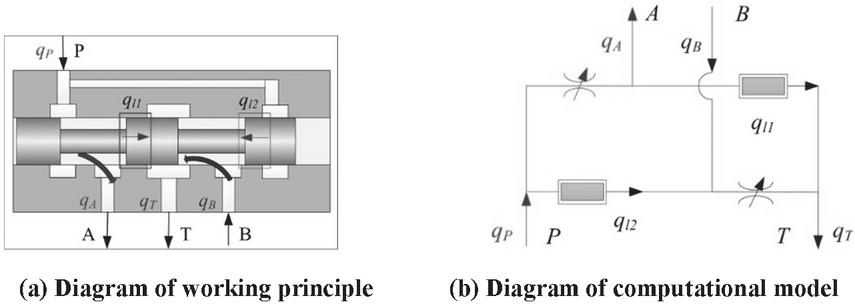
Figure 4 Schematic diagram of the reversing valve.
The internal leakage diagnosis
When the leakage occurs, the flow of reversing valve can be expressed.
| (11) | |
| (12) | |
| (13) | |
| (14) |
Combining Equations (11) and (12),
| (15) |
So, the leakage estimator can be selected.
| (16) |
Due to the low accuracy when using two flow signals at the same time, it can be judged by combining the pressure signal.
So, the leakage can also be expressed.
| (17) |
The leakage estimator is obtained below.
| (18) |
The spool opening diagnosis
The insufficiency of reversing valve opening causes throttling. Using the actual output pressure and input pressure, the theoretical flow can be calculated. Therefore, the fault can be analyzed by the difference between the theoretical flow and the actual flow.
The normal opening is , and the opening coefficient is (), When the opening is , the actual flow at port P is obtained.
| (19) |
So, the deviation estimator of the flow can be expressed.
| (20) |
By selecting the flow deviation estimator, it is possible to judge whether there is any fault in reversing valve, but it cannot be determined whether the specific fault is caused by internal leakage or opening insufficiency. Therefore, it is necessary to judge the fault type according to the other changes from pressure and flow. In general, when leakage occurs, the pressure in valve becomes lower, when opening fault occurs, the pressure in valve becomes higher.
3 Simulation
Based on mathematical models of typical components, the fault analysis and diagnosis of hydraulic system is simulated. According to the working principle, the simulation models based on AMESim are established, as shown in Figure 5.
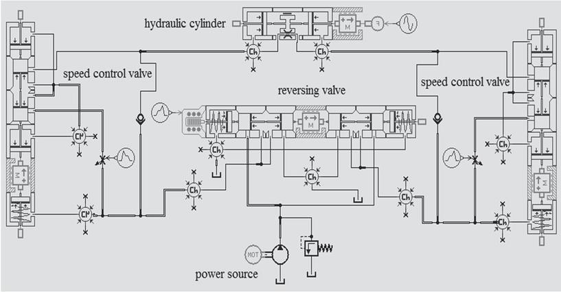
Figure 5 Simulation models of telescopic hydraulic system.
The simulation models mainly include hydraulic cylinder, speed control valve, reversing valve and relief valve. The related parameters are shown in Table 1.
Table 1 The settings of parameters in simulation models
| Parameter | Value |
| Maximum working pressure | 10 Mpa |
| Maximum load | 5400 N |
| Shaft speed of motor | 1000 rev/min |
| Pump displacement | 5.5 cc/rev |
| Piston diameter | 40 mm |
| Rod diameter | 20 mm |
| Length of piston stroke | 170 mm |
| Maximum flow rate at reversing valve | 8 L/min |
| Orifice diameter of speed control valve | 5 mm |
3.1 Analysis of Single Fault
3.1.1 Internal leakage in cylinder
The clearance between the cylinder and the piston is set from 0 mm to 0.4 mm, and the simulation results are shown in Figure 6. When supplied by a fixed displacement pump, the flows rate at port A and port B are shown in Figure 6(a). The flow rate difference is obtained by formula 4, as shown in Figure 6(b). It indicates that internal leakage increases as clearance increases, and the expanding speed of piston decreases with the increase of clearance. Conversely, if the flow rate difference is known, the value of clearance in the hydraulic cylinder can be diagnosed.
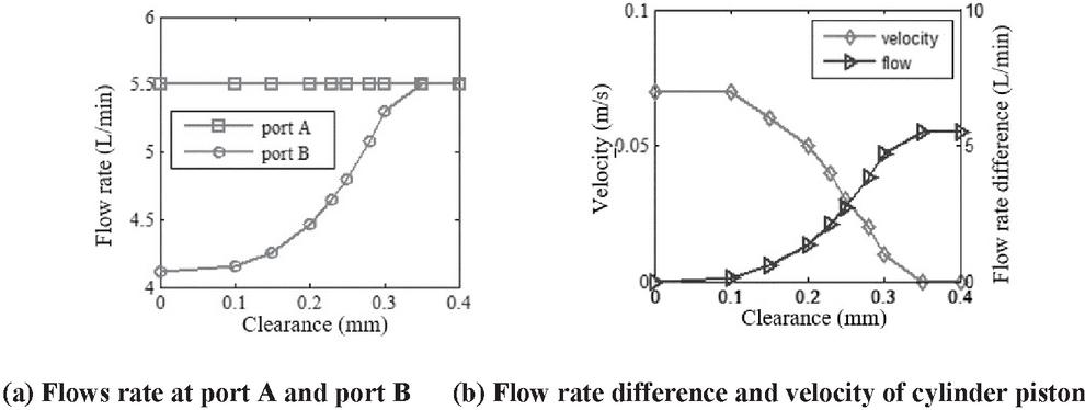
Figure 6 Related curves of internal leakage in cylinder.
3.1.2 Blockage in speed control valve
In the blockage simulation, the orifice diameter in speed control valve ranges from 0 mm to 5 mm. The flow rate varies with changes of orifice diameter, as shown in Figure 7. The theoretical flow rate can be obtained by injecting fault pressures to the normal valve, as shown in Figure 7(b). By calculating the difference between theoretical flow and actual one, the flow difference is obtained, as shown in Figure 7(b). In addition, the velocity of piston keeps increasing as the orifice diameter increases. The maximum velocity remains 0.07 m/s when the diameter reaches 2 mm. As can be seen, the flow deviation and velocity can be used as the basis for fault location for speed control valve.
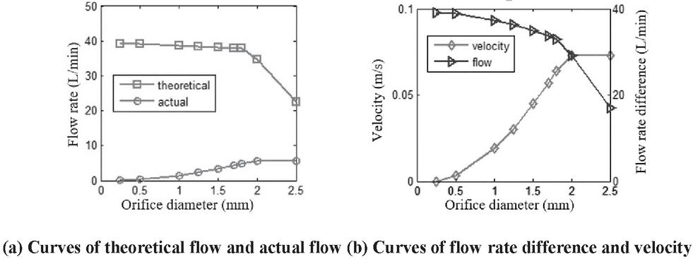
Figure 7 Related curves of blockage in speed control valve.
3.1.3 Opening in reversing valve
As shown in Figure 8, the opening coefficient of the reversing valve ranges from 0 to 1. Through direct measurement, the actual flow is measured and the value is shown in Figure 8(a). The theoretical flow rate can be obtained by injecting the actual pressures to the mode.
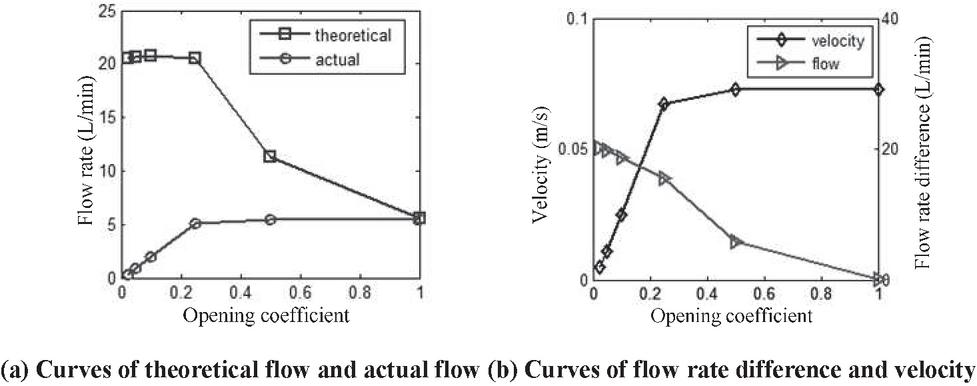
Figure 8 Related curves of reversing valve in opening fault.
Figure 8(b) shows the deviation of the flow rate in reversing valve. The value decreases with the increase of opening coefficient, which indicates the fault become less, the curve of piston velocity indicates that the speed becomes larger as opening coefficient increases, and it cannot increase after the opening coefficient reaches 0.5. All the above information can be used as the basis for fault diagnosis for reversing valve.
3.2 Multiple Faults Simulation and Diagnosis
To verify the applicability of fault diagnosis, the simulation of hydraulic system which contains multiple faults is carried out. In the case, the fault modes include: the insufficient opening of reversing valve, the blockage of speed control valve and the internal leakage in cylinder. The faults parameters are shown in Table 2.
Table 2 The settings of parameters in the fault series
| Item | Opening Coefficient | Orifice Diameter | Cylinder Clearance |
| Series 1 | 30% | 2.5 mm | 0.25 mm |
| Series 2 | 20% | 3.5 mm | 0.15 mm |
| Series 3 | 60% | 1.5 mm | 0.2 mm |
Among the above faults, the opening fault in series 2 is the worst, and series 3 is the lightest. Also, the blockage of speed control valve in series 3 is the worst, the internal leakage in series 1 is the worst. According to the principle of fault diagnosis, all the faults in the system should be diagnosed and the fault severity of each component should be distinguished.
3.2.1 Simulation results
The simulation results of three fault series are shown in Figures 9 and 10. Figure 9 depicts the displacements of cylinder piston, the solid line is the curve of the system without fault, and the other three lines are the curves of piston motion in three fault series, respectively. It can be seen that all the motion of three series reach the predetermined position later than that of normal system, which means failures. By further measurement, the flow curves of different series are obtained, as shown in Figure 10. In the normal system, the flow rate into hydraulic cylinder is 5.5 L/min, which is not accessible to the other three faults series.
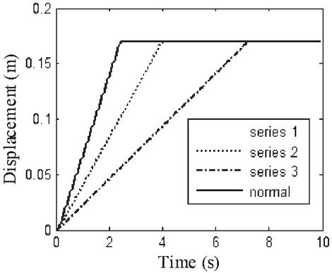
Figure 9 Displacements in different series.
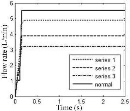
Figure 10 Flow curves in different series.
Comparing Figure 9 with Figure 10, we find that the flow rate in series 1 is greater than that in series 2, but the speed in series 1 is lower than that in series 2. So, it shows that the severity of the fault in the series is not certain, and this problem must be solved by testing specific component in each series.
3.2.2 Component diagnosis
All the curves of reversing valve flow rate in three series are shown in Figure 11. When the theoretical flows minus the actual flows respectively, the three series flow deviations are shown in Figure 12. The figure shows that the maximum deviation is produced in series 2, which means the maximum failure, and series 3 has the least deviation, which is the lightest fault. This diagnosis is also consistent with the initial settings of fault severity.
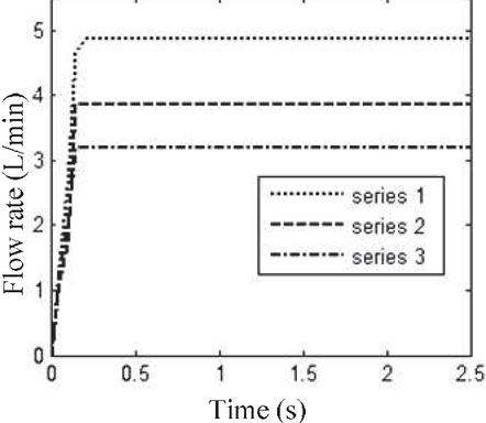
Figure 11 Flow rate at port P in reversing valve.
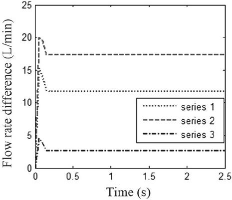
Figure 12 Flow rate difference in reversing valve.
Similar to the diagnosis and analysis of reversing valve, the difference curves of the theoretical flow rate and the actual one in the speed control valve is obtained, as shown in Figure 13. According to the numerical value, it can be seen that series 3 has the most serious faults, series 1 is lighter and series 2 is the lightest, which fully conforms to the previous setting of orifice diameter in speed control valve.
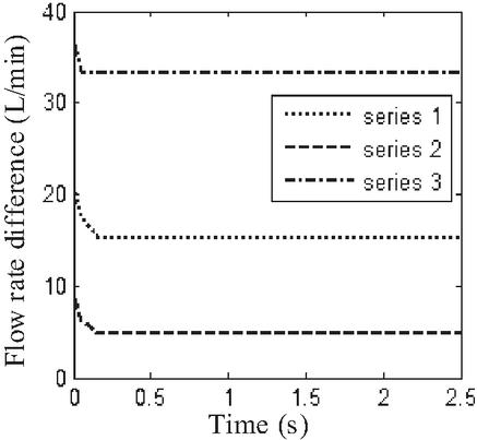
Figure 13 Curves of flow rate difference in speed control valve.
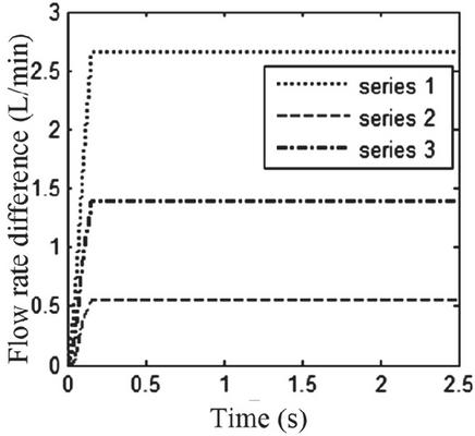
Figure 14 Curves of flow rate difference between the ports in cylinder.
According to the internal leakage flow formula, the flow rate difference of hydraulic cylinder leakage is calculated, as shown in Figure 14. As we can see from the figure, in series 1, the internal leakage 2.64 L/min is the largest. In series 2, the leakage 0.55 L/min is the smallest, which is consistent with settings of the cylinder clearance.
4 Experiments
4.1 Test System
There are so few downhole robots, the cost and the time of failure testing for the actual system are high and large. Therefore, some fault is imitated to study fault characteristics and fault diagnosis. In the internal leakage, a throttling valve is set in parallel with the cylinder to simulate the internal leakage with variable sizes. Thus, the internal leakage experiment can be carried out. The schematic diagram of experiment system is shown in Figure 15.
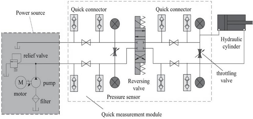
Figure 15 Schematic diagram of experiment system.
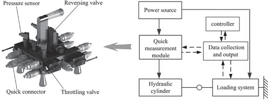
Figure 16 Diagram of wiring of experiment system.
In Figure 15, the experiment system consists of three parts: power source, quick measurement module and hydraulic cylinder. The quick measurement module is used to measure flows and pressures of the inlet and the outlet of cylinder. There are ball valves between both adjacent quick connectors. After placing ball valve in the closed state and connecting flow sensor between both quick connectors, the flow in the pipeline can be measured.
Figure 16 shows diagram of wiring in experiment system. The solid line in the figure represents the hydraulic flow. The power source not only provides pressure and flow for the telescopic mechanism, but also provides energy for the loading system. The dotted line is the signal transmission line, in which the controller sends out instructions to make hydraulic components and sensors work.
Based on experimental principle and connection mode, the internal leakage experiment system is established, as shown in Figure 17.
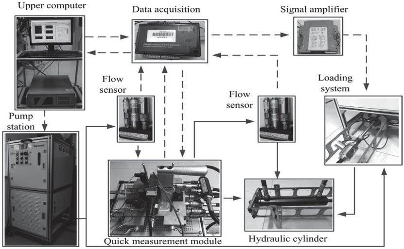
Figure 17 Physical map of internal leakage experiment system.
4.2 Results and Discussions
When the operation is stable, the relevant data is obtained and plotted. In the experiment, the simulating leakage clearance of the cylinder is set by 0 and 0.2 mm, and the corresponding displacements of cylinder piston are shown in Figure 18. In addition, the theoretical curves for the settings of 0 mm and 2 mm are added. It can be seen that when the cylinder has no failure, the displacement in the experiment is almost identical with the simulation displacement, where external leakage and pipe leakage are not considered. When the cylinder clearance is 0.2 mm, the trend of experimental displacement is similar to that of simulation analysis.
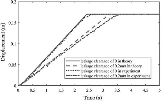
Figure 18 Curves of displacement in the experiment and simulation.
Further verification of the leakage diagnosis is performed, namely, the selected leakage estimator. The experimental estimators are obtained by introducing the flows of hydraulic cylinder ports. When the cylinder is not leaking, the deviation estimators are shown in Figure 19, whose mean value is about 0 L/min. When the cylinder leakage is 0.2 mm, the deviation estimators are obtained as shown in Figure 20, whose mean value is around 1.5 L/min. The estimators fluctuate because of the effects of noise and other vibrations. Compared with theoretical result, the mean deviation should be near 1.37 L/min, which is less than the experimental value. The reason is that there may be amount of other leakages in the operation, including pipeline leakage and external leakage.
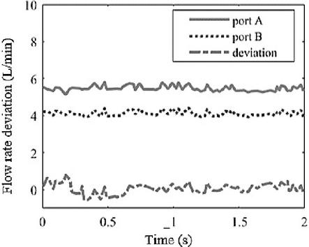
Figure 19 Curves of the flow without internal leakage.

Figure 20 Curves of the flow with internal leakage.
From the experimental data and graphs, the experiment can simulate internal leakage characteristics of the hydraulic cylinder. Moreover, the method of deviation estimator proposed in this paper can correctly locate and diagnose the leakage and severity of the cylinder.
With the leakage experiment, the fault characteristics and data of each leakage dimension can also be collected, which is provided for the fault diagnosis. In addition, based on the similar experiment principle, it can also collect fault characteristic for other hydraulic components including directional valve, speed control valve and even overflow valve, which is helpful to establish the fault information database for the downhole traction robot hydraulic system.
5 Conclusions
In this paper, the fault analysis and diagnosis of downhole traction robot hydraulic system were proposed with some simple but effective arguments and measurements.
The structure of downhole traction robot was introduced, and its working principle and operation feathers were analyzed. With the help of the analysis of failure mode and mechanism in the key components, the fault diagnosis of hydraulic system was proposed based on the mathematical model. Based on simulation, the fault model of downhole traction robot hydraulic system was established, and the diagnosis of single fault and multi-fault were simulated, some fault data and characteristics were found and collected. Experiments of simulated leakage in hydraulic cylinders were established, and schemes of fault diagnosis were carried out, which can validate the feasibility of the diagnostic method.
For future research, the following work is to collect more and more fault data and characteristics on hydraulic components.
References
[1] Liu Q, Zhao J, Zhu H, et al. Review, classification and structural analysis of downhole robots: core technology and prospects for application[J]. Robotics and Autonomous Systems, 2019, 115: 104–120.
[2] Jianzhong Shang, Delei Fang, et al. Design and Analysis of a Hydraulic Drive Downhole Traction In-pipe Robot Based on Flexible Support Structure[J]. Proceedings of Institution of Mechanical Engineers, Part C: Journal of Mechanical Engineering Science. 2021, 235(1):18–27.
[3] Fang Delei, Shang Jianzhong, et al. Axiomatic Design for Purely Hydraulic Drive In-pipe Robot[J]. Journal of national university of defense technology. 2019, 41(6):63–69.
[4] Saeed A, French A, Moore N B. Analysis and Case Study: Comparing CT Slim Tractor Performance Using Different CT Sizes in 3 Wells[C]//SPE/ICoTA Well Intervention Conference and Exhibition. OnePetro, 2020.
[5] Duthie L, Saeed A, Shaheen S, et al. Design Transformation of Hydraulically Powered Coiled Tubing Tractors for Matrix Acidizing Stimulations in Extended Reach Carbonate Reservoirs[C]//Abu Dhabi International Petroleum Exhibition & Conference. OnePetro, 2017.
[6] Murtaza S, Hajri M A, Saeed A S, et al. Deployment of One of Its Kind Slim Coiled Tubing Tractor to Overcome Reach Issue in Extended Reach Restricted Smart Completed Wells[C]//SPE Asia Pacific Oil & Gas Conference and Exhibition. OnePetro, 2020.
[7] Sharifi, Siavash, Tivay, et al. Leakage fault detection in Electro-Hydraulic Servo Systems using a nonlinear representation learning approach[J]. ISA Transactions, 2018(73):154–164.
[8] Raduenz H, Mendoza Y E A, Ferronatto D, et al. Online Fault Detection System for Proportional Hydraulic Valves[J]. Journal of the Brazilian Society of Mechanical Sciences and Engineering, 2018, 40(7):331–338.
[9] Effect Analysis of Leakage in the Middle Position and Improvement of an O-type 3-position-4-way Directional Valve with the Spool Structure[A]. Xuyao Mao, Chao Wu, Hongyuan Ding, Bin Li, Yiou Liu. Proceedings of 6th International Conference on Energy Materials and Environment Engineering, 2020, 508(1):012160.
[10] Fault diagnosis of automobile hydraulic brake system using statistical features and support vector machines[J]. Jegadeeshwaran R, Sugumaran V. Fault diagnosis of automobile hydraulic brake system using statistical features and support vector machines[J]. Mechanical Systems and Signal Processing, 2015, 52:436–446.
[11] He D, Hu N, Wang M. Study on real-time fault injection and simulation of mechanic-electronic-hydraulic control system based on AMESim and LabVIEW[C]// Prognostics and System Health Management Conference (PHM-2014 Hunan), 2014. IEEE, 2014:446–450.
[12] He Yuming, Peng Likun, Song Fei. Simulation Based on AMESim for Internal Leakage of Hydraulic Slide Valve[J]. Chinese Hydraulics & Pneumatics, 2018(5):74–80.
[13] Bahrami M, Naraghi M, Zareinejad M. Adaptive super-twisting observer for fault reconstruction in electro-hydraulic systems[J]. Isa Transactions, 2018(76):235–245.
[14] Zhou Xiaojun. Jiang Lehua. Gao Jingwei. Simulation Analysis for Inner Leakage of Hydraulic Cylinder Based on AMESim[J]. Machine Tool & Hydraulics. 2012, 40(23):147–150.
[15] Zhang Jing, Hu Zhongquan, et al. Analysis of Leakage Fault Injection for A10VNO Pump Based on AMESim[J]. Hydraulics Pneumatics & Seals, 2021, 41(07):69–73.
[16] Chen Minjie, Yang Rongjin. Fault Simulation and Diagnosis Technology of Hydraulic System for Hydraulic Support[J]. Chinese Hydraulics & Pneumatics, 2021(1):128–132.
Biographies
Delei Fang received the B.S. degree from the Hebei University of Science and Technology and the M.S. degree from Yanshan University in 2014, and the Ph.D. degree from the National University of Defense Technology, Changsha, China, in 2018. He is currently a Lecturer with the Tianjin University of Science & Technology. His research areas include mobile robot, hydraulic system integration and energy efficient hydraulic components.

Yong Xue received the Ph.D. degree in mechanical engineering from the National University of Defense Technology, Changsha, China, in 2016. He is a researcher with Beijing Special Engineering Design Institution. His research interests in hydraulic machinery and equipment.

Guofeng Jia received the B.S. degree in vehicle engineering from Luoyang Institute of Technology, in 2020. He is currently working toward the M.S. degree at the Tianjin University of Science & Technology. His research interests include hydraulic control technology and fluid power component.
Pan Li received the B.S. degree from the Department of Mechanical Engineering, Wuhan Polytechnic University, China in 2012. She received the Ph.D. degree at the Department of Mechanical Engineering, Tianjin University, Tianjin, China in 2019. She is currently a lecturer in Tianjin University of Science & Technology.

Jie Tang received the M.S. degree at the Department of Mechanical Engineering, Yanshan University, Qinhuangdao, China in 2010. He is currently an associate professor in Aviation Engineering Institute, Civil Aviation University of China. His research interests include fluid transmission and control.

Xiaoming Wang received the Ph.D. degree at the Department of Mechanical Engineering, Tianjin University, Tianjin, China in 2009. He is currently a lecturer in Tianjin University of Science & Technology. His research interests include underwater vehicles and embedded control systems.
International Journal of Fluid Power, Vol. 24_3, 513–536.
doi: 10.13052/ijfp1439-9776.2435
© 2023 River Publishers