Flow Field Characteristics and Structure Improvement of Double-stage Safety Valve
Zhao Guochao1,*, Yin Shi1, Song Yuning2 and Wang Hui1
1College of Mechanical Engineering, Liaoning Technical University, Fuxin, Liaoning, 123000, China
2Department of Mechanical and Power Engineering, Yingkou Institute of Technology, Yingkou, 115014, China
E-mail: abczgccba@126.com
*Corresponding Author
Received 09 April 2022; Accepted 18 November 2022; Publication 12 June 2023
Abstract
The paper proposes a new double-stage large flow protection relief valve based on the double-stage linkage structure, to solve the problem that when it is impacted by the top plate, the traditional hydraulic support protective relief valve has smaller overflow and lower sensitivity, which causes the column circuit to be damaged. The flow field characteristics of double-stage protective relief valve are numerically simulated by the computational fluid dynamics method and semi-implicit connection pressure equation calculation model. Then the dynamic characteristics of the flow field distribution of the double-stage protective relief valve are obtained. According to the law of fluid flow, the structure of main valve core is optimized for the negative pressure, cavitation and vortex area. The flow field characteristics of the optimized double-stage protection valve are simulated and analyzed. In the end, the flow field characteristics of optimized double-stage protective relief valve are compared with the original. The results show that the negative pressure value of double-stage protective relief valve is reduced by 15%, and the outlet velocity of double-stage protective relief valve is reduced by 21% compared to the unoptimized when the main core is fully opened. The research results provide reference for the evolution design of high-flow, impact-resistant hydraulic support safety valve structure.
Keywords: Hydraulic support, double-stage safety protection valve, flow field, dynamic characteristic.
1 Introduction
The development trend of coal mining working face is comprehensive mechanization and unmanned, and the work efficiency and safety performance requirements of coal mining and operation process are constantly improved [1]. The hydraulic support is one of the core equipment of fully mechanized mining face. The safety valve installed on the column is an important part of the hydraulic support. It is used to limit the actual working resistance of the hydraulic support so that it does not exceed the allowable value [2]. Compared with the single-acting safety valve used in traditional hydraulic supports, it cannot solve the insignificant random impact caused by the vibration of the equipment [3], so it is required to design a two-stage protection large-flow safety valve for the hydraulic support that can meet the needs of different working conditions.
In recent years for safety protection valve design, Li [4] has designed a new type of differential high-pressure large-flow safety valve. The fluid-structure coupling simulation is performed by ADINA software, and the dynamic characteristics of the safety valve are simulated in AMESim software. Guo Yongchang [5] proposed a dynamic and static loading test bench for safety valves, and verified the correctness of the simulation results of the safety valve flow field through experiments. Guo [6] used Simulink module in MATLAB to build the simulation model of safety valve and analyzed the impact resistance characteristics. In addition, a hydraulic circuit is built, and MATLAB and AMESim are used to simulate the unloading capacity of the two-stage safety valve after impact. Han Fengxia [7] used CFD DESIGN to analyze the flow field of the spool of the safety valve and carried out experimental verification. Literature [8] made a statistical analysis of the massive damage of the hydraulic support safety valve of Holsinghe Mine, and proved that the quality of the hydraulic oil and the excessive impact load are the main reasons for its damage. Literature [9–12] carried out hydrodynamic analysis and simulation of the spool of the safety valve from the perspective of fluid mechanics. At present, there are few researches to solve the negative pressure, cavitation, cavitation and vortex area of the main spool. This paper proposes a new high-flow safety protection valve based on the double-stage linkage structure, and makes structural optimization for the above problems.
In there, for the process of opening-overflow-closing of the two-stage safety valve when the hydraulic support roof is subjected to a large impact load, for the partial flow field of the main spool, with the help of computational fluid dynamics method, the Semi-Implicit Method for Pressure Linked Equations calculation model and RNG - turbulence model, numerically simulate in the flow field of the main spool of the two-stage safety valve is implemented, and the Origin software is used to fit numerically the characteristic streamline to obtain the change of the internal flow field of the safety valve during the opening of the main spool rules and optimize and improve the structure.
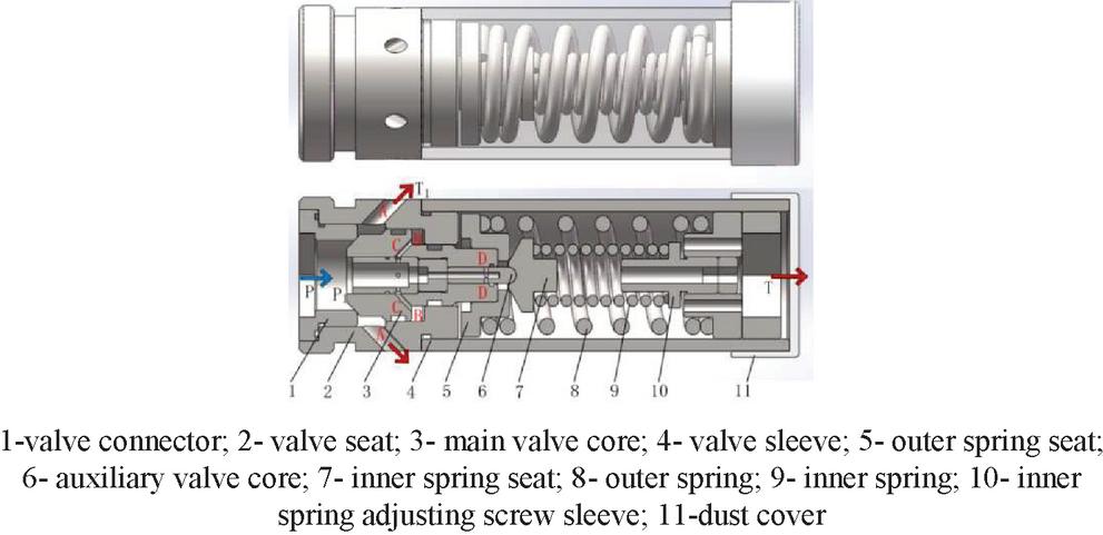
Figure 1 Structure of double stage protective relief valve.
2 Structural Characteristics and Working Principle of Safety Valve
Based on the design of direct-acting relief valve and differential cone valve linkage structure, the hydraulic support has a two-stage high-flow safety valve structure design, which is divided into two-stage safety valves, of which the first-stage uses a small-flow direct-acting structure (Secondary spool), the second stage adopts a large-flow differential structure (The main spool) [13], and its internal structure is shown in Figure 1.
The working principle of the two-stage safety valve is connected to the hydraulic support column circuit. When the top plate of the hydraulic support is less impacted or the support vibrates, when the pressure in the lower chamber of the column rises to the opening pressure of the auxiliary valve core, the direct-acting valve opens. The liquid flows out from the jet port on the dust cover of the safety valve, so that the pressure in the lower cavity of the column can be controlled. When the top plate pressure is large and the top plate sinks faster, resulting in a large impact load, the pressure in the lower cavity of the support column suddenly rises. At this time, the main valve core opens and the high-pressure liquid flows out through the outlet A, and the column is quickly Unloading to ensure the stability of the entire circuit of the hydraulic support.
The rated flow and rated pressure of the first-stage direct-acting valve. When the pressure fluctuation range of the column circuit is small, a certain amount of liquid is discharged to ensure the stability of the circuit pressure. Due to its structural limitation, the first-stage direct-acting valve has a small flow and opening pressure Relatively low; the rated flow and rated pressure of the secondary differential main valve. When the column circuit produces large pressure fluctuations due to the impact of the roof, the circuit is unloaded and protected by discharging a large amount of high -pressure liquid, so that the safety valve is in the situation of sudden pressure changes. Can maintain a good unloading capacity.
3 CFD Simulation of Flow Field Characteristics of Double-Stage Safety Valve
3.1 Computational Model Calibration
Among several equations of computational fluid mechanics, Semi-Implicit Method for Pressure Linked Equations based on velocity-pressure coupling is currently the main method for solving the characteristics of incompressible liquid flow field [14]. Boundary conditions are u,v as the initial value of the velocity component in the x direction and y direction, and the pressure p is derived by the momentum equation [15].
The controlling equation for flow and heat transfer is:
| (1) | |
| (2) | |
| (3) |
Where is the fluid density, is the dynamic viscosity.
The initial state of the flow field is stationary, Re indicates the dimensionless number of fluid flow. When the flow reaches a steady state, the x-direction dimensionless velocity U, the y-direction dimensionless velocity V.
The dimensionless incompressible Navier-Stokes equation is:
| (4) | |
| (5) |
Integrating over the equation:
| (6) | |
| (7) | |
| (8) |
Using the finite volume method to discretize the equations, the discretized continuity equation is:
| (9) |
The discretized momentum equation is:
| (10) |
Where a and b are the coefficient and constant terms; and the others are the terms related to the number of iterations.
When the first iteration is performed, the initial pressure value is defined, the velocity component after the first iteration can be obtained according to Equation (10), and the initial pressure value is corrected according to the velocity component. The pressure correction equation is:
| (11) |
The corrected pressure value and velocity component are used to modify the velocity value. The velocity correction equation is:
| (12) |
Where A is used to calculate the area of the micro element.
It can be seen from the fluid mechanics that a mass conservation equation and three momentum conservation equations form an Navier-Stokes equation system, but when using the Reynolds average method for time averaging, Navier-Stokes equation system is not closed. In order to close the equations, the - model is introduced, namely the turbulent flow energy equation and the turbulence dissipation rate equation. The standard model will produce certain turbulence models with strong swirl, curved wall flow and other turbulence models. The RNG - model corrects the turbulent viscosity, which is more efficient for liquid flow processing with high strain rate and a large degree of streamline bending [16], so the RNG - model is selected for this problem shown as Equation (3.1).
Where is the turbulent viscosity; is the turbulent kinetic energy; is the turbulent dissipation rate; and are the turbulent model constants.
3.2 Fluid Model Operation
The main content of the simulation analysis of the internal flow field of the double-stage protection large-flow safety valve is the process of the spool from opening to full opening. The opening size of the two-stage differential spool is 1.0 mm, 3.0 mm and 5.5 mm by extraction Flow channel, numerical simulation of the distribution law of working medium pressure and velocity in the internal flow field of the two-stage safety valve from open to fully open [16]. The flow path model of the safety valve when the opening size of the main valve core is not optimized is 5.5 mm, as shown in Figure 2.
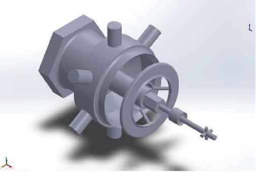
Figure 2 Model of the double stage protective relief valve.
The pressure inlet boundary and pressure outlet boundary are used in the FLUENT solution calculation. The inlet boundary is the left end, and the outlet boundary is 6 liquid outlets of the second-stage differential valve and 4 liquid outlets of the first-stage direct-acting valve. According to the design sample of the two-stage safety valve, the rated opening pressure of the safety valve is 50 MPa, the maximum pressure overshoot is 25%, so the inlet pressure is set to 62 MPa, and the outlet pressure is standard atmospheric pressure. The fluid medium in the hydraulic support is a high water-based emulsion, which is made up of 5% emulsified oil and 95% neutral water, and its fluid properties are similar to water. CFD simulation is used to obtain the pressure characteristic distribution cloud diagram of the gradual opening of the safety valve.

Figure 3 Pressure contour chart.
3.3 Fluid Model Verification
As can be seen from Figure 3, when the safety valve is gradually opened under the set pressure, the pressure of T1 port gradually decreases, which is the same as the result in literature [7]. In order to verify the accuracy of CFD simulation, the experimental bench as shown in Figure 4 is established.
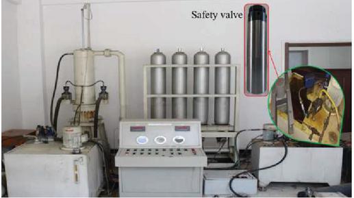
Figure 4 Experimental bench.
The outlet pressure of the safety valve is tested. When the safety valve is stably opened under the pressure of 62 MPa, the T1 outlet pressure is tested for many times. The average value is about 34.53 MPa, the CFD simulation pressure is 36.48 MPa, and the relative error is 5.35%. The experimental value is slightly lower than the simulated value at the stable opening of the second-stage differential spool, ignoring the effect of pressure fluctuation of the experimental system and the accuracy of the sensor, which can prove the validity of CFD simulation and the accuracy of the model.
4 Result Analysis
Two-stage safety valve main spool fully open flow field internal pressure and velocity streamlines are shown in Figures 5 and 6, respectively.
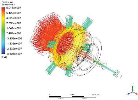
Figure 5 Pressure distribution of the safety valve.
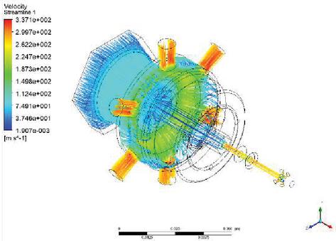
Figure 6 Velocity distribution of the safety valve.
As can be seen from Figure 5, the pressure drop when the working medium flows through the two-stage differential valve is mainly concentrated at the annular cross-flow cross section of the main spool, and a local vortex area is generated at the sudden pressure change, and it can be seen at the outlet of the auxiliary spool There is a negative pressure at the outlet of the main spool. It can be seen from Figure 6 that as the working medium is largely released from the opening of the secondary differential spool, the velocity change in the overflow area of the secondary differential valve is large, because the working medium affects the The impact makes the flow velocity of the working medium change the most drastically here, and the probability of cavitation and cavitation is greatly increased here.
The occurrence of negative pressure areas is prone to cavitation and cavitation, and the dramatic changes in flow rate are also one of the reasons for cavitation and cavitation. It is possible to reduce the chance of cavitation and cavitation by reasonably changing the structure and size of each component, thereby reducing local pressure impact and noise. At the same time, as the differential valve releases a large amount of high-pressure and high-speed working medium, in the over-flow area where the structural change occurs, the vortex area is prone to appear due to the separation of the outflow from the valve body wall. Therefore, if the safety valve continues to work under this condition, the corrosion of the valve body and the loss of pressure will gradually become severe, which seriously affects the safety and working life of the safety valve [17].
The dynamic characteristics of the main spool of a two-stage safety valve are quantitatively analyzed. The flow fields with spool openings of 1 mm and 3 mm were analyzed respectively. Select the pressure and velocity at a series of points on the central streamline from the inlet to the outlet, and use. Origin to fit the simulation data to obtain the internal pressure and velocity of the main spool opening size of 1 mm, 3 mm and 5.5 mm respectively. The distribution law is shown in Figures 7 and 8.
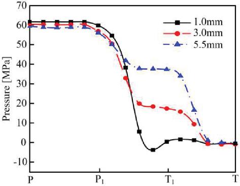
Figure 7 Full flow channel pressure under different main vavle core opening sizes.
Figure 8 Full flow path velocity under different main valve core opening sizes.
It can be seen from Figure 7 that when the size of the spool opening is 1 mm, the inlet pressure of the safety valve is 61.69 MPa. As the opening of the main spool increases, the inlet pressure decreases to 59.32 MPa. The pressure at the entrance of the main spool decreases from 59.55 MPa to 55.99 MPa with the increase of the spool opening, and the pressure drop at the annular cross-flow section of the main spool gradually decreases. The pressure drop decreases from 56.98 MPa to 19.13 MPa, and then stabilizes Reduce to atmospheric pressure. Finally, there is a certain negative pressure value at the outlet of the valve sleeve of the safety valve. It can be seen from Figure 8 that when the opening of the main spool is 1 mm, the flow velocity of the inlet of the safety valve is 28.61 m/s, and the maximum flow velocity is 287.06 m/s at the annular cross-section of the main spool. As the opening of the main spool increases, the flow velocity at the inlet of the safety valve gradually rises to 73.15 m/s, the maximum flow velocity of the main valve spool cross-section decreases to 192.55 m/s and the maximum flow velocity appears before the outlet of the safety valve is 314.30 m/s. It can be seen that with the opening of the main spool, the maximum flow rate is transferred from the annular flow cross section of the main spool to the outlet of the safety valve. The flow velocity of the working medium in the entire flow channel generally shows a trend from low to high along the direction of the streamline. Among them, the flow velocity at the annular flow-through interface has a tendency to increase first and then decrease, and there is a certain speed fluctuation at the outlet of the safety valve. It is caused by the structure of the runner.
During the simulation, the results were found to be unsatisfactory. The main reason was that the unreasonable structural design resulted in pressure loss and the appearance of vortex zones. Based on the results of the flow field analysis, further structural optimization plans are as follows:
Compare the pressure and velocity distribution near the main spool and auxiliary spool outlets, and change the outlet of the differential valve to a 45 uniformly distributed outlet to reduce the inner wall surface of the outlet near the outlet Shock. In addition, the pressure and velocity at the junction of the main spool liquid outlet and the inner wall of the valve sleeve change greatly, and cavitation and vortex areas are prone to occur. Therefore, rounds are added to increase the impact caused by the structural mutation. The structure of the safety valve is adjusted according to the optimization result of the safety valve structural characteristics. The optimized two-stage safety valve flow channel model is shown in Figure 9. After that, the flow field is simulated again, and the simulation results are shown in Figures 10 and 11.
Figure 9 Improved model of the safety valve.
Figure 10 Improved pressure distribution in the flow channel.
Figure 11 Improved velocity distribution in the full flow channel.
It can be seen from Figures 10 and 11 that from the inlet of the safety valve to the inlet of the main spool is similar to the unmodified flow field, but when the spool opening is 1 mm, the negative pressure area disappears at the cross-section of the auxiliary spool, and the The negative pressure value before the outlet of the safety valve is reduced by 12% compared with that before the improvement, and the negative pressure value when the spool opening is 5.5 mm is reduced by 15% compared with the unmodified one. According to the figure, the fluctuation of the flow rate is reduced, and the outlet flow rate is reduced to 236.49 m/s when the spool opening is 5.5 mm, which is a 21% year-on-year decrease.
It can be seen from the process of opening to full opening after the optimization of the main spool structure that the pressure and flow velocity distribution of the main spool at the liquid outlet is more uniform, and the range of negative pressure is greatly reduced. That is to reduce the probability of cavitation, cavitation and vortex area. Because the pressure shock and vibration are reduced, the stability and reliability of the safety valve during the working process have been greatly improved.
5 Conclusion
This paper proposes a two-stage safety valve in hydraulic support and CFD is used to dynamically simulate the flow field of the safety valve. The main conclusions are as follows:
(1) When the working medium flows to the outlet through the annular cross-flow cross section of the main spool of the two-stage safety valve, a obvious negative pressure area and vortex area appeared, which seriously affects the safety and working life of the safety valve.
(2) After optimizing the local structure of the safety valve, the probability of occurrence of cavitation and vortex areas in the internal flow field is greatly reduced. After the main spool is fully opened, the negative pressure value is reduced by 15% compared with that before the optimization. The flow rate is reduced by 21%, which effectively improves the performance of the two-stage safety valve.
Acknowledgment
This work was supported by the National Natural Science Foundation of China under Grant 52204169, Liaoning Provincial Natural Science Foundation (2022-YKLH-07) and Liaoning Provincial Department of Education Scientific research fund project (L2020011).
References
[1] Lei Junbo, et al. “Flow model and dynamic characteristics of a direct spring loaded poppet relief valve.” Proceedings of the Institution of Mechanical Engineers, Part C: Journal of Mechanical Engineering Science 232.9 (2018): 1657–1664.
[2] Liao Yaoyao, et al. “Effects of multiple factors on water hammer induced by a large flow directional valve.” Strojniski Vestnik/Journal of Mechanical Engineering 64.5 (2018): 329–338.
[3] Yang Liu, et al. “Experiments and transient simulation on spring-loaded pressure relief valve under high temperature and high pressure steam conditions.” Journal of Loss Prevention in the Process Industries 45 (2017): 133–146.
[4] Li Geqiang, et al. “Design of a high water-based fluid, high-pressure, and large-flow safety valve.” The Journal of Engineering 2019.13 (2019): 79–85.
[5] Yong Chang, et al. “Performance Analysis of Large Flow Safety Valve for Powered Support.” Chinese Hydraulics & Pneumatics 01 (2019): 71.
[6] Guo Chenghu, and Jun Mao. “Anti-impact load characteristics of two-stage safety valve for hydraulic support.” Ain Shams Engineering Journal 13.5 (2022): 101738.
[7] Han Fengxia. “Application of CFD in Safety Valve Spool Design of Hydraulic Support.” Coal Mine Machinery (2014), 35(10): 218–220.
[8] Li Xiaobai, Zhang Liang, Wang Dongpan. “Analysis on causes of large number safety valve failure in powered supports of high cutting coal mining face.” Coal engineering (2014), 46(04): 57–59.
[9] Szurgacz, Dawid, and Jarosław Brodny. “Analysis of the influence of dynamic load on the work parameters of a powered roof support’s hydraulic leg.” Sustainability 11.9 (2019): 2570.
[10] Zeng, X. T., G. Y. Meng, and J. H. Zhou. “Analysis on the pose and dynamic response of hydraulic support under dual impact loads.” International journal of simulation modelling 17.1 (2018): 69–80.
[11] Zeng Qingliang, et al. “Analysis on force transmission characteristics of two-legged shield support under impact loading.” Shock and Vibration 2018 (2018).
[12] Zong Chaoyong, Feng Jiezheng, and Xue Guansong. “Understanding lift force discontinuity of pressure safety valve.” Pressure Vessels and Piping Conference. Vol. 58967. American Society of Mechanical Engineers(2019).
[13] Wang Hui, Song Yuning, Zhao Guochao, et al. “Emulation analysis about dynamic behaviors of overload protection safety valve with twin-stage.” Journal of Liaoning Technical University (Natural Science) (2017), 36(07): 750–754.
[14] Scuro, N. L., et al. “A CFD analysis of the flow dynamics of a directly-operated safety relief valve.” Nuclear Engineering and Design 328 (2018): 321–332.
[15] Zhao Boyuan, Li Jiangfei, Wang Yafei, et al. Numerical Simulation of Square Cavity Flow with SIMPLE Algorithm [J]. Liaoning Chemical Industry, 2016, 45 (06): 760–763.
[16] Yun, Z. H., et al. “Flow Field Analysis Based on CFX for New Type of Synchronous Valve.” Chinese Hydraulics & Pneumatics 03 (2019): 126.
[17] Barbaryan, T., et al. “Developing a low-fluid pressure safety valve design through a numerical analysis approach.” International Journal of Numerical Methods for Heat & Fluid Flow (2019).
[18] Zong, Chaoyong, et al. “Computational fluid dynamics analysis and extended adaptive hybrid functions model-based design optimization of an explosion-proof safety valve.” Engineering Applications of Computational Fluid Mechanics 16.1 (2022): 296–315.
Biographies

Zhao Guochao received the Ph.D. degree in mechanical Design and theory from Liaoning Technical University in Fuxin, China, in 2020. He is a lecturer at the School of Mechanical Engineering, Liaoning Technical University. His main research direction is mechanical system modeling and simulation.

Yin Shi received the B.E. degree in mechanical design manufacture and automation from Liaoning Technical University, Fuxin, China, in 2021. She is currently pursuing the master’s degree in mechanical engineering from Liaoning Technical University, Fuxin, China, in 2021. Her current research interests include mechanical system modeling and simulation.

Song Yuning received the B.E. degree in mechanical design manufacture and automation from Liaoning Technical University, Fuxin, China, in 2012, and the PH.D. degree in mechanical design and theory from Liaoning Technical University, in 2018. He is currently a associate professor with the School of Mechanical and Power Engineering, Yingkou Institute of Technology. His current research interests include mechanical system modeling and simulation.

Wang Hui received the B.E. degree in mechanical engineering from Liaoning Technical University, Fuxin, China, in 1982, and the PH.D. degree in mechatronic engineering from Harbin Institute of Technology, Harbin, China, in 2005. He is currently a professor and doctoral supervisor with the School of Mechanical Engineering, Liaoning Technical University. His current research interests include include mechanical system modeling and simulation.
International Journal of Fluid Power, Vol. 24_3, 589–606.
doi: 10.13052/ijfp1439-9776.2438
© 2023 River Publishers