A Review of Pilot-operated Hydraulic Valves – Development, Challenges, and a Comparative Study
Essam Elsaed1, 2,* and Matti Linjama1
1Faculty of Engineering and Natural Sciences, Tampere University, Finland
2Faculty of Engineering Ain Shams University, Egypt
E-mail: essameldin.elsaed@tuni.fi
*Corresponding Author
Received 12 April 2022; Accepted 05 April 2023; Publication 06 November 2023
Abstract
Hydraulic systems have been widely used due to their high power-to-weight ratio. Despite the growing instances of being superseded by the electromechanical counterparts at low power levels, the market was incapable of presenting alternatives for large-size applications. Additionally, in recent years, the demand for more significant heavy machinery (Mobile & Industrial) has increased, which led to the necessity of even higher flow and pressure Pilot-operated valves, despite the fact that these valves have several issues. One might think the alternative could be developing a hydraulic system that does not rely on Pilot-operated valves, but after decades of research, these systems could not get close to the performance of Pilot-operated Multistage valves.
The paper presents a comprehensive study of the progress accomplished from the year 2016 to early 2022 in hydraulic Pilot-operated valves; they are widely employed among ordinary valves, proportional valves, and state-of-the-art digital hydraulics. Higher efficiency will be a primary factor in the success of the new designs.
The academia presented several studies to improve the Pilot valves’ performance, but still, they are limited. There are no dramatic developments, and there are only a few upgrades.
Keywords: Pilot valves, multistage valves, large valves, high flow valves, high pressure pilot-operated valves.
1 Introduction
1.1 Motive, Data collection and Limitations
Pilot hydraulic circuits are broadly spread at the fluid power terrain (Mobile machinery, automotive, aerospace, oil & gas, industries, etc.) with no worthy rival in large-size applications, albeit their defaults. On top of that, according to the best of the Authors’ knowledge, this article is the first published study (at least since 2016) to review Pilot-operated valves works. Additionally, specifically tailored information about Pilot valves is not found directly, and usually, it is scattered among other components in the scientific books. Add to that the broad definition of ‘Pilot’ term itself in the fluid power field, clarified later. Moreover, a qualitative, straightforward comparison between Pilot operated valves and other competing technologies is not easily available. A well-organized filtration process (Figure 1) was done to realize nonbiased, wide-range, topic-focused articles.
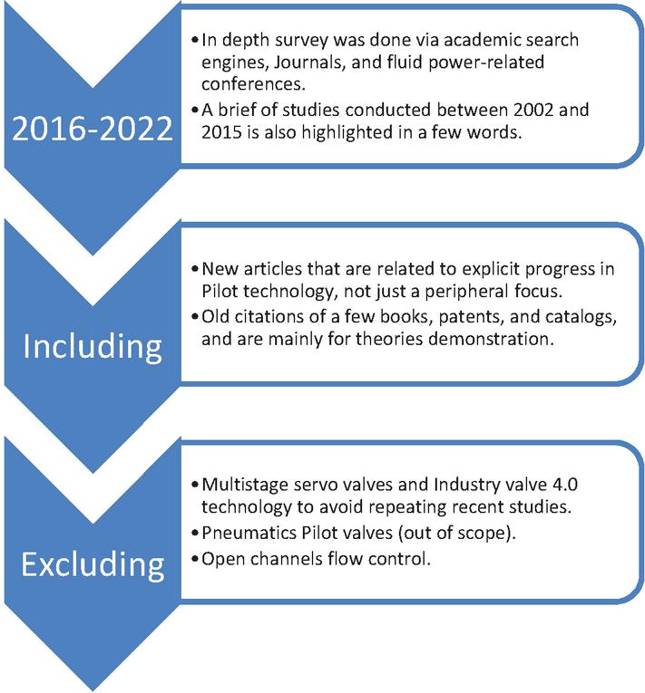
Figure 1 Data collection and delimitations phases.
1.2 Historical Overview
Pilot valves have been around for quite a while. It is tough to say precisely who invented them or when they were invented. The earliest related patent that is on hand was written by S. Chase & H. Chase back in 1869 [1]; their invention was applied in steamships to the feed or discharge pipes of the vessels when the pipes lead to or from the sea. In the older valve versions, it was life-threatening to reach the valve in case of accidents; and the inventors aimed to present a valve located at a convenient distance and operated from the engineer’s room or even from the ‘Pilot-house’. A couple of years later, the term ‘Pilot valve’ was shown in a registered study for improving balance valves employed in steam engines [2].
1.3 Pilot Terminology in Fluid Power
1.3.1 Definitions and interpretations of the ‘pilot’ word
As a general rule, hydraulic components need an actuation force; this force could be electrical, mechanical, or fluidic. Usually, the term ‘Pilot’ or “Multistage” is used with fluidic (hydraulic or pneumatic) operated devices, and they are commonly available in large power applications.
An early definition of ‘Pilot’ terminology was mentioned by an engineering design handbook [3], which stated that a Pilot is ‘a valve applied to operate another valve or control element.’ While Pilot-operated is ‘a valve in which operating parts are actuated by Pilot fluid.’ Similarly, a recent book confirmed the exact old definition; the ‘Pilot’ signals (flow) represent the control signals to the main power stage. The word ‘Piloting’ describes the low power control signal that goes into the main power stage control elements (valves) [4].
Notably, in some instances, hydraulic machinery could have a separate loop (loops are represented by the number of pumps that are employed to supply the main functions of a hydraulic machine) for Low-pressure systems, one of its uses is to maintain a Pilot pressure necessary to operate hydraulic control valves and variable displacement units [5, 6].
Meanwhile, in the fluidic actuation process of Multistage directional valves, the Pilot valve is essentially a proportional pressure reducing valve (reduce the Pilot valve supply pressure to a pressure that is proportional to the command signal/lever, which is then connected to the corresponding spool cap of the main control valve). In short, the main valve spool is moved in proportion to the output Pilot pressure [4, 5]. This info ought not to be misinterpreted with the requirement of some commercials valves that a pressure reducing valve be inserted for the input Pilot pressure source, if the available supply pressure is high, such as with the EATON AxisPro 4/3 Pilot operated proportional valve series [7]. A counter case (Presented here not for the sake of superiority evaluation) offered by Parker Hannifin; the corporation developed analogous Pilot-operated valves with no pressure-reducing valve required, i.e., D*1FC series [8].
What is more, the Pilot term should not be mistaken with the term ‘remote.’ A typical hydraulically controlled circuit may consist of a pumping unit, DCVs, and a cylinder. The pumping unit and the main control valves can be remote Pilot-operated or remote electrically operated [9]. Remote refers to a remote location or far control, such as the case with Rexroth presented valves [10–12].
In Pilot flow control valves, two stages, such as Pilot operated poppet-type valves, the Pilot valve, and the main valve spools could be: (I) in a single package and work harmonically, (II) or they could be separated when bidirectional flow control is required. The main prime mover of the Pilot valve in the two configurations is commonly a solenoid actuator [13, 14].
Another fair usage for the ‘Pilot’ term is with displacement-controlled systems (variable displacement pumps) [15]. In the pump controller or compensator, the swash plate angle is controlled by a Pilot-pressure-related control that adjusts the pump’s displacement in proportion to the Pilot control pressure. The required control pressure is taken either from the load or externally applied Pilot control pressure [5].
1.3.2 Pilot components related systems and applications
In a few words, Pilot technology is extensively spread among (a) valve-controlled hydraulic systems [16], (b) displacement control “open-circuit”, and (c) displacement control “closed-circuit”; only the (d) direct-drive hydraulics systems with a second compensation pump that does not use Pilot operated valves technology [17].
In an interesting brochure by Eaton [18], the ranges of usage for spool proportional valves were mentioned, and it will be shown later that direct valves are available till size NG10 (equivalent to D05). Consequently, Multistage valves are typically used in flow rates more than 180 L/min, such as utility construction vehicles, entertainment motion bases, flight simulator motion bases, sawmill set works, injection molding, crawler vehicles, rolling mills, oil explorations, and die casting.
1.4 Classification and Selective Pilot Components Working Theory
Fluid control elements can be reduced into two basic component groups: Pressure controls and Flow controls [19].
1.4.1 Pilot-operated flow & directional control valves
The Pilot operated directional valve (two stages) has a Pilot (secondary) stage and a main stage. The Pilot section (Pilot valve spool) controls the pressure and direction of fluid flow to the main spool. The fluidic actuation of the Pilot stage could be trigged by (mechanical actuation, pneumatic actuation, hydraulic actuation) [20] or electrical actuation.
Flow forces: When a fluid passes through control orifices in a typical spool valve, it is analogous to that through a nozzle. The change in momentum of fluid running through a nozzle demands an external force to be applied against the fluid. This force is called ‘flow force’; simply put, it is the force that reacts on the valve’s spool. In larger valves operated by solenoids, the flow force (at high flow rates) might be large enough to require force amplification for the main actuator, and this can be realized in a Pilot operated valve [21].
Bernoulli forces limit the flow capacity of single-stage valves; generally, for flow rates under 190L/min, a single-stage direct actuated valve is sufficient. [4]. For a spool valve, the force required to open/close the valve is determined by the orifice diameter and pressure difference over that valve.
1.4.2 Pilot-operated pressure control valves
Generally, pressure control valves involve two or three port connections; and the spool which controls the orifice area is actuated based on a sensed pressure. Various types of Pilot operated pressure-control valves are available, i.e., relief valves, unloading valves, counterbalance valves, reducing valves, and sequence valves. The counterbalance/holding valve and unloading valves are other variations of the relief valve, whereas the sequence valve and pressure-reducing valve have some similar features [21, 22].
The above-mentioned valves can be categorized again into two forms, internally Piloted and externally Piloted. When the Pilot signal to open the valve is from a source other than the line feeding it, it is called “externally Pilot”. Internal Pilot lines can monitor input/primary port as the case in pressure relief valve and some configurations of sequence and counter valves, or monitor the valve output as in the case with pressure reducing valve. External or remote Pilot lines (at the output port) can be found in unloading valves and some configurations of sequence and counterbalance valves [3, 23–25].
1.4.3 Dual-functional valves
Depending on the design and implementation, valves can serve either as pressure control or flow control valves. For instance, Open-center valves can function as in-between flow and pressure control valves by adjusting the spool position, such as the Rexroth 4/3 WE series spool valves [26]. In other words, partially restricting fluid flow provides fine flow control, while blocking flow diverts fluid to a secondary circuit or a relief valve to maintain desired pressure. Another notable offering in the high flow rate market is the Pilot operated HYDAC L-CEE 2-way cartridge poppet valve [27], which boasts flow rates up to 10800 LPM. That valve can perform directional or pressure functions. Specifically, it can be combined with a stroke-limited control cover and Pilot valve to produce a switch or check function in the context of directional flow. Also, it may be employed as a safeguarding mechanism for pumps or cylinders when operating for controlling the pressure.
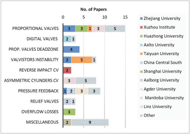
Figure 2 Contribution of the research institutes articles mentioned in the challenge section (2016–2022).
(1) Universities with only one publication per challenge are mentioned in the “Other” horizontal bar.
(2) The survey does not necessarily represent all the publications of a specific university per challenge published anywhere, but only those who comply with the criteria defined in Section 1.1.
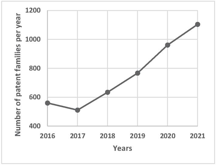
Figure 3 Developing trend of Pilot valve technology over the years (2016–2022) [28].
1.5 Research Interests, Prospect and Layout
Main academic development
Figure 2 reveals the number of cited articles per challenge (shown later in Section 2) and highlights the research institutes studying these areas.
Trend of Pilot valves studies
A survey was done using Espacenet patents search (which contains nearly 130 million patent documents) [28] to determine the research figure of Pilot/Multistage related technology over the past 6 years. Search terms and operators were used to exclude irrelevant material such as servo valves and pneumatic Pilot operated valves. Among the refined results, Figure 3 shows an increasing pattern starting from 2017.
Layout
The paper will focus merely on Pilot operated valves. The core part of the paper will categorize the related challenges and presents researchers’ solutions. In the subsequent chapter, a case study of commercially Pilot valves will be shown and analyzed. Lastly, alongside alternative actuation systems, the conclusion paragraph is discussed briefly.
2 Challenges and Innovations
In this section, new possibilities for the Pilot technology’s inherent problems will be presented as follows:
2.1 Flow Control
Table 1 Flow control section qualitative comparison
| Challenge | Field of Development of Pilot Operated Valves |
| 2.1.1.1 |
1. Stress analysis for ultra-high pressure valves. 2. Grooves geometry optimization. 3. Sealing and the leakage. |
| 2.1.1.2 |
1. Optimized Pilot pressure. 2. PWM control signal. 3. Spool design. 4. Stability of the Proportional directional valve (PDV) using water as a hydraulic fluid. 5. Valve spring. |
| 2.1.1.3 |
1. Stability of the PDV using water as a hydraulic fluid. (ex. Hurwitz stability criterion). 2. Pilot valve spring. 3. Valve grooves. 4. Valve control (ex. state feedback control). 5. Valve chamber area. 6. System integration (mechanical, electronic, electromagnetic, and fluid dynamic subsystems). |
| 2.1.2 |
1. Valve size. 2. Internal Piloting supply. 3. Leak-free valves. 4. Pressure drop across the valve. 5. Valve body deformation. |
| 2.1.3 |
1. Modelling of the dead band. 2. Spool design. |
| 2.1.4 |
1. Intelligent controller (fuzzy & neural network). 2. PWM & operating frequency. 3. System design (pressure differential compensator). |
| ➢ All the tabled challenges have valves with separate or combined packages for the Multistage valve. | |
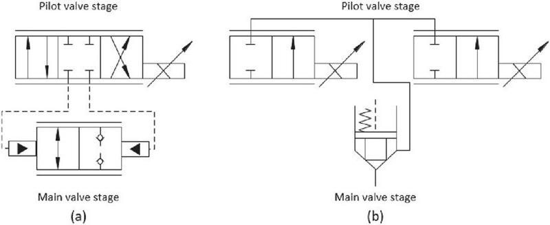
Figure 4 Different implementation for the two-way hydraulic proportional cartridge valves.
2.1.1 Response time in Pilot operated proportional valves
Two-way valve improvement
In a large hydraulic forging press, having proportional control components to perform reliably under ultra-high-pressure and large-flow conditions is considered a significant challenge. A prototype DN25, 70MPa two-way proportional cartridge valve was produced at Yanshan University [29] for a large hydraulic transmission system of a forging press. The Pilot piston of the valve is controlled by a 4/3 direct-drive servo-proportional valve, while an LVDT sensor is installed at the top. The Pilot rod is integrated into the main valve spool, as presented in Figure 4.(a) The experimental results prove that the response time of the valve is 23.5 ms and the maximum flow at the main valve port is 429 L/min at p 0.5 MPa. This study was built over a simulation analysis for cartridge proportional flow valve performed at Xi’an Jiaotong University [30].
Furthermore, Han et al. [31] developed a large-flow water hydraulic proportional cartridge valve prototype, as shown in Figure 4.(b) A voice coil motor (an efficient electrical-mechanical conversion device) was used to actuate the Pilot valve. It has the advantages of high speed and high control accuracy to actuate the Pilot valves (In this same context, Parker Hannifin patented voice coil drive that has high dynamics and precision with Pilot operated nominal sizes up to NG32 [32]). The main (2-way spool cartridge) and Pilot (2-way spool, proportional) valves have an LVDT displacement sensor and an eddy current displacement sensor, respectively. The experimental results indicate that the step response rising time of the valve is about 20–30 ms, and the flow rate can reach 1100 L/min at p 1 MPa.
Three-way valve improvement
Moving on to another progression, high-speed switching valves (HSVs) are recommended to be employed in Pilot control due to their low power loss, oil contamination resistance, and digital control superability. Nevertheless, there are still difficulties between response time and discrete flow.
In an attempt to investigate the above question, Wang et al. [33] used two 3/2 high-speed switching ball-valves (one on each control chamber) to Pilot a 3-way main stage spool valve. They regulate the duty cycle of the PWM control signal (for the discrete flow valves) in order for the main valve stage to output continuous flow and pressure. The main factors influencing the main stage response time were recorded: Pilot HSV frequency, control chamber pressure, and the PWM control signal. The simulated rated flow and pressure of the developed Pilot valve are 2 L/min and 2 MPa, respectively. Whereas the main stage valve has rated flow and pressure of 200 L/min and 35 MPa, respectively. In a recent study, the research team implemented in an Independent Metering Valve (IMV) system four 3/2 high-speed valves on the Pilot stage and two 3/3 proportional valves on the main stage [34]. Experiment results show that compared with traditional proportional valve and proportional Pilot twin spools valve, IMV system based shows faster and more robust performance.
Taiyuan University [35] simulated a PWM to control a 3/2 water hydraulic main valve proportionally in the Pilot stage. A water hydraulic proportional valve is more difficult to design than an oil hydraulic proportional valve. The analysis shows that increasing pulse-width modulation carrier frequency is an effective way to reduce fluctuation amplitude. Later, Zhang et al. [36] proposed a prototype water hydraulic proportional directional valve to solve the pressure fluctuation issue in the main control chamber when previously using PWM.
Four-way valve improvement
A water hydraulic system employing tap water as a working fluid provides high speed, high-output control while maintaining safety and eco-friendliness [37]. Cartridge valves are more capable of large flow (screw-in cartridge valves’ flow rate is about 150L/min, whereas slip-in cartridge valves have flow rates of 200–7000 L/min at p 5 bar [4]), requiring less stringent machine tolerances and having very low leakage. Besides that, poppet valves have strong anti-pollution capability and ease of manufacturing when water is used as a pressure medium. In light of previous points, the poppet valve is rather (often) selected as the main core of the cartridge valve in water hydraulic systems.
In order to overcome the fundamental trade-off between the flow capacity and response in Pilot valves; a group of researchers at Huazhong University [38] Modeled four high response 2/2-way water hydraulic proportional valves as the Pilot stage and a cartridge poppet valve as the secondary stage, to create an equivalent 4/3-way proportional valve. They optimized (via Genetic Algorithm) the structure parameters to improve the valve performance. In the following year [39], they optimized (via ANSYS/Fluent) the valve to reduce (by 10%) the axial flow forces acting on the spool of a cartridge valve.
Another group of researchers at Beijing University [40] studied a seawater hydraulic cartridge-type 4/3 directional valve. Four cartridge type, 2-stage poppet valves were adopted as the main valves, while two high speed on/off solenoid valves were utilized as the Pilot stage. The experimental results reveal that the damping hole diameter of the cartridge valve, the control chamber area, and the flow rate of the Pilot valve have essential impacts on the dynamic characteristics of the valve. The valve rated pressure and flow are 14 MPa and 120 L/min, while the dynamic opening and closing response times are 109 ms and 128 ms, respectively.
Using high speed on/off valves as well, the Technical University of Sofia [41] conducted an experiment to improve the tracking accuracy of a 4/3 Pilot-operated proportional (spool) valve; they criticized the oscillations of the flow rate and pressure signals of the switching valves, which limits the achievable bandwidth of the closed-loop system. Notably, the aforementioned technology is utilized in low-speed heavy-duty machines, such as in the electrohydraulic steering unit (OSPE Steering Valve) by Danfoss [42].
With progress in the airplane industry, the electro-hydraulic actuated landing gear is required to retract as quickly as possible to improve the climbing speed [43]. The PDV are less sensitive to contamination but respond slower than the servo valves.
Zhang et al. [44] studied precisely the utilizing of Pilot operated PDV in the landing gear. The valve package consists of a 4/3 Pilot-PDV with a 4/3 Main-PDV, both have spool structure. A pressure of 10 MPa and a flow rate of 200 L/min is used to power the system. A pressure reducing valve is used to stabilize the supply pressure for the Pilot valve so that the effect of the external pressure can be reduced, while an inductive position transducer measures the actual main spool position. The experimental results revealed that the electromagnetic force delay and the Pilot valve deadzone (The region or band of no response where an error signal will not cause a corresponding actuation of the controlled variable [45]) are the two main factors affecting the time response.
➢ Concluding speech: High flow rate was possible in 2-way valves with good response time, and PWM is mainly used in operating the Pilot stages 3/2 and 4/3 way valves.
2.1.2 Digital valve (Parallel Connected) systems response time
Equivalent to 4/3 proportional valve
Digital hydraulic valve systems have multiple fluid power advantages over spool-type proportional valves [46]; however, the currently available digital valve systems are large and slow.
To accelerate and minimize the digital valve system, Lantela and Pietola at Aalto university [47] proposed a digital valve system that performs better than a specific direct operated 4/3 proportional valve, i.e., Parker Hannifin D1FP. The proposed valve system consists of 32 spool-type Pilot operated miniature on/off valve. Its step response is approximately 2 ms at p 10 MPa (intriguingly faster than the direct valve), while the flow rate per control edge at p 3.5 MPa is 78 L/min. However, since the valves are hydraulically operated, their response time increases significantly below a pressure difference of 1MPa; this is an inherent property of Pilot operated valves. A confirmation remark by Ketonen et al. [48] stated that Pilot controlled on-off valves have a high level of uncertainty, which can cause state transition problems when switching the valves in the digital flow control unit (Bundle of parallel-connected on/off valves).
Equivalent to 2/2 proportional valve
For a second time, under the supervision of Prof. Pietola; Saleem presented a master thesis discussing the analysis of the dynamic characteristics of the Pilot-operated logic valve [49]. A 2/2 bi-directional two-stage, slip-in cartridge valve (Parker Hannifin CE016) is used for the main stage, while for Piloting the cartridge valve, two 2/2 solenoid-operated valves (Bucher Hydraulics WS22) were utilized, and it can perform as on/off valves or extended to act as 2/2 proportional valves or a continuous switching valve, as schemed in Figure 5. It has concurred that the proposed valve package can have 27 ms at 200 L/min when p 80 bar. Nevertheless, the switching time was rather low at higher operating pressure, and it was noticed that the Piloting of the main valve is susceptible to unstable control if it is internally Piloted.
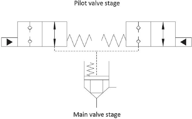
Figure 5 Two-stage cartridge valve, Piloted by two on/off valves [49].
Motivated by this technology, Zardin et al. at the University of Milan [50] studied (CFD analysis) the possibility to extend the range of pressure and flow by 30% for on/off cartridge valves, subsequently extending the application range of digital hydraulics. They also defined three requirements for cartridge valves; (1) low-pressure losses, (2) high time response which depends on the behavior of the Pilot stage, (3) and a settled valve against load dynamics.
➢ Concluding speech: digital hydraulics is a verified technique to solve accompanied problems of traditional hydraulic components; however, few developments have been accomplished to extend the flow capacity of this technology.
2.1.3 Deadzone in Pilot proportional directional control valves
Most directional control valves are of a spool-type construction; the spool has lands and undercuts. Another point to consider in the valve center position is the lap condition (Figure 6). There are three types of lap conditions: (I) Line to line, critical center or zero lap valves are available in servo valves, or servo performance closed-loop valves with spool position feedback (such as KBS direct-acting and KBH Pilot-operated servo performance valve families, manufactured by Eaton [51]), too bad these valves are hard to manufacture. (II) Underlapped. (III) Overlapped. Most proportional valves are overlapped, resulting in a slack motion or dead-band (deadzone). In simple words, the spool must move a certain distance before any flow is delivered to the actuator ports [21, 22].
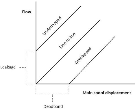
Figure 6 Lab conditions for spool proportional valves [22].
The most conventional method to decrease the adverse impact of dead-bands nonlinearity is to add a dead-band inverse function; this will compensate for the dead-band effect. This method is effective only for the condition that the dead-band in the Pilot stage (in the case of a two-stage valve) is accurately estimated. However, the actual dead-band values are usually poorly known.
Motivated by the above observations, researchers at Zhejiang University have accomplished improvements in a two-stage, 4/3-proportional spool valve. In the early stages, Xu et al. [52] defined the relationship between the flow rate and the Pilot valve position as a cascade deadzone model, consisting of not only the center deadzone, but also the intermediate deadzones. The test settings for the proportional valve pressure and flow rate were 35 MPa and 200 L/min, respectively; simultaneously, the Pilot inlet pressure was kept constant at 4 MPa.
Despite the previous endeavors, the deadzones introduced by the overlaps of the Pilot stage cause a switching delay in the valve (Rexroth/4WRKE) [53]. Therefore, researchers [54] proposed a proportional valve with an independently controlled Pilot stage. (cutting the traditional Pilot valve spool into two parts) hence, shortening the dead zone length that the proposed Pilot valve spool needs to travel across. Consequently, the valve has a quicker response speed, a weaker damping effect, and a lighter weight. The experimental results show that the tracking error decreases from 6.21% to 2.6% in a specific scenario. What is more, due to the gap and leakage of the Pilot valve, there is a micro flow rate when the Pilot valve spool has positive overlaps. In recent research [55], they proposed a deadzone detection method that includes the micro flow rate in the intermediate position of the Pilot valve.
➢ Concluding speech: seldom research institutes were interested in this challenge, and development was on the component structure level. New control approaches were also studied.
2.1.4 Instability in a Pilot controlled proportional valve with internal displacement-flow feedback
In high flow rates (two stages) IMVs, the orifices in the conventional (one piece) spool valve cannot be individually controlled; therefore, the 2/2 Poppet valves seem a trending research topic for the main stage of modern independent metering systems. (A glance from the market shows spool structure is more dominant for moderate flowrates Independent Metering Systems, such as in Eaton CMA-200L/min [56] & Danfoss PV32-130L/min [57] Pilot operated valves). Advantageously, several designs allow proportional control for two-stage valves with a sort of internal feedback loop, which can take one of several forms [58]: (alternatively stated in [19]).
• Electric feedback servo performance.
• Force ‘spring’ feedback servo.
• Mechanical feedback servo.
• Combined force feedback and follow-up servo.
• Hydraulic position feedback (Valvistor principle).
The Pilot-controlled proportional valve with internal displacement-flow feedback, initially proposed by Andersson at Linkoping University, is the focus of this section. The valve has a simple structure, low production costs, and high flow rates. The feature that makes it a Valvistor is that the main stage is connected hydraulically to the Pilot stage. Thus, it realizes servo-type control of the main stage without utilizing an electric transducer on the main stage (such as Eaton Valvistors slip-in cartridge valves [59]), as shown in Figure 7. In Valvistors, a minimal Pilot flow is used to actuate the large main flow [58]. In doing so, the valvistor concept has the ability to conserve Pilot flow, as the Pilot flow is returned to the valve outlet [59].
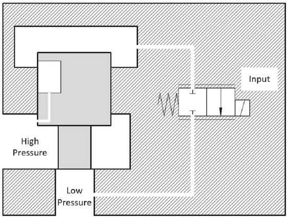
Figure 7 Schematic of the Valvistor main stage with a proportional valve as the Pilot control [58].
Another point to consider is the that transducers on the two-stage proportional (Infinitely variable directional) valves could be:
• Open-loop (Force controlled, not servo performance)
∘ with no sensors [22].
• Closed-loop:
∘ Transducers could be placed on the main stage or both stages [60, 61].
∘ External feedback, where the position/force feedback from the actuator itself [7].
∘ Valvistors also could have transducers in the Pilot stage. In Eaton Valvistors HFV family (flow ratings up to 2160L/min) [62], their design achieves servo-type control of the main poppet, and LVDT was only used on the Pilot stage valve spool.
The Taiyuan University of Technology has a head start in publishing articles about developing Valvistors in recent years. A certain issue for these valves is the flow rate and load relay on each other (if a load dependent Pilot valve is used) ; in view of this problem, Wang et al. [63] proposed a control strategy for a two-stage proportional valve, which consists of a 2-way poppet valve (Vickers/EPV16) used as the main valve and a 2/2 proportional valve (Vickers/TG4V) as the Pilot stage. To diminish this reliance, they introduce a novel control strategy using a Fuzzy PID controller and the backpropagation Neural network algorithm.
Whereas Xiong et al. [64] proposed a two-stage digital flow control valve, in which the main stage is a Valvistor poppet valve, and the Pilot stage consists of four 3/2 fast-switching valves (Rexroth 4WRPEH) used in PWM mode, as presented in Figure 8. The benefits of the proposed configuration are continuous outlet flow and large flow capacity.
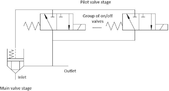
Figure 8 Schematic diagram of a Valvistor two-stage digital flow control valve [64].
An alternative approach to compensate for pressure variations is to allow pressure drop to change freely, then regulate valve opening as a function of both desired flow and measured pressure drop; this is called digital pressure compensation and is usually utilized in small flow control applications. Advantages are simple structure and efficiency because there is no measuring orifice or mechanical compensator. Based on this hypothesis, Huanga et al. [65] presented a two-stage proportional flow control valve with a Pilot digital pressure compensator. The proposed valve comprises two pressure sensors, a 4-way proportional Pilot valve (Rexroth 4WRPEH), and a Valvistor poppet valve as the main stage. The Pilot valve compensates for the pressure influence on the outlet flow by interpreting the pressure drop signals across the Pilot valve metering orifice.
A unique strategy using a Pilot pump is presented in this paragraph. In further detail, based on the Valvistor principle, the Pilot stage is worked as a throttle valve. Accordingly, when working pressure or pressure drop is low enough, proper pressure drop cannot be established between both ends of the valve spool, weakening the valve’s controllability and dynamic response. On the other hand, the way to eliminate the influence of the Load variety by using a pressure differential compensator and flow transducer escalates the pressure loss of the valve and the valve’s complexity, meanwhile diminishing flow capacity. On that account, Hao et al. [66] used a displacement pump driven by a servo motor as a Pilot stage. The Pilot pump flow is hardly affected by system pressure. Consequently, the new valve can function under very low pressure.
In a recent study, a novel Integral-separation fuzzy PID controller is proposed [67] to improve the valve performance further. The Valvistor valve package comprises a Pilot stage 2/2 proportional solenoid (Vickers-EPV16) and a main stage/poppet type valve (Rexroth-SYDFEE-20). An LVDT is connected to the Pilot stage. The valve was tested at different flow rates and pressures, up to 120 L/min and 9 MPa.
➢ Concluding speech: Although these above methods [59-62] can eliminate the effect of the load change on the flow, the flow accuracy is still not at its best performance. Besides, the bandwidth is very narrow given that the structural feature is not changed. Furthermore, due to disturbance factors, including flow force, pressure fluctuation, and machining error, the flow rate through the main valve is not absolutely proportional to the Pilot flow, reported by the same research group in a 2021 study [67].
2.2 Pressure Control
In this section, development in Pilot operated pressure control valves was summarized in Table 2, as the main objective of this review paper is to study Flow control Multistage valves.
Table 2 Pressure control section recent research studies [2016–2022]
| Challenge | Problem Statement in Brief | Sample of Studies |
| Reverse impact in Pilot check valves | Reversing impact load conditions causes intense vibration in valve ports of large-flow check valves [22, 68]. | [69, 70] |
| Displacement control for asymmetric cylinder systems | For a differential cylinder (single rod cylinders), the oil flows through the two chambers are different. Therefore, either excess or low flow rate is continuously created in the closed-circuit [5, 71]. There are several solutions for the unbalanced flow rates compensation problem: (I) use of multiple pumps [72, 73], (II) a single pump combined compensating valves (Pilot operated check valves [74], 3/3 shuttle valves [75], or on/off solenoid valves [76]) and (III) Asymmetric pumps [77]. | [78–83] |
| Pilot Pressure feedback | The self-contained system (Only consumes energy when motion is demanded) shows better energy efficiency as opposed to the valve-controlled cylinders, which employ pressure-compensated proportional directional control valves (PDCV)s and counter-balance valves [80]. A popular configuration is to use PDCVs in combination with Over-Center Valves. Nevertheless, this approach tends to introduce an oscillatory behavior or even instability. | [84–94] |
| Design of Pilot operated relief valves | In the main stage of a Pilot-operated relief valve, the valve can be opened in case of sharp, dynamic transients, even if the pressure setting of the Pilot stage is not met, i.e., the Pilot stage is still closed. | [95–97] |
| Overflow energy loss in Pilot proportional relief valve | Energy losses in valve-controlled hydraulic systems are divided between throttling loss in control valves and overflow loss in relief valves. Overflow loss is one of the main concerns regarding the inefficiency of the hydraulic system. | [98–100] |
| Pressure control units in heavy duty automatic transmission | The following articles are concerned with the Pressure control valve in the clutch engaging /disengaging operation. High power automatic transmissions widely utilize the Pilot-operated electrohydraulic clutch-actuator system; high precision and fast actuator response performances are critical to maintaining the shift quality for these systems. Nevertheless, inappropriate system parameters can generate self-excited vibrations, for instance, Pilot-operating pressure [5, 101]. | [102–106] |
| Perceived stimuli in hydraulic operation lever with a hydraulic Pilot valve | In construction machinery controlled by an operation lever with a hydraulic Pilot valve, it is known that operators manipulate the machine based on subtle operational reaction forces in the operating lever [5]. These articles showed the possibility of developing a novel control lever interface to enhance operational sensing. | [107–109] |
| Optimization, Fault identification and Simulation | Pilot valve parameters optimization techniques. | [110–112] |
3 Survey Insights: Two Decades Period, Excluding Last 6 Years
In this section, a brief overview of research conducted on Pilot operated valves in the last twenty years is presented. A significant proportion of studies are related to control and dynamic stability, such as controlling a typical two-stage 2/2 poppet valve [113], exploring the dynamic performance of a two-stage 2/2 force feedback poppet valve system [114], and investigating the dynamic performance of Eaton EPV-16 cartridge type Valvistor [115, 116]. Also developing a control strategy for a two-stage poppet valve to be used in IMS [117], Lastly, proposing a method for modeling uncertainty in a Pilot-operated 4/3 proportional valve [118].
Other studies focused on modifying valve design to improve valve performance, To name a few, reducing flow resistance by replacing a 4/3 spool valve with four Pilot operated logic cartridge valves [119]. Moreover proposing a novel 4/3 internal flow feedback cartridge valve [120], Additional studies related to utilizing poppet HSVs as the Pilot stage for 2/2 [121], for 4/3 main valves [122], and for a three-stage high flow rate directional valve [123].
Further researches were conducted to optimize the design parameters for a two-stage, 2-way hydraulic valve for water hydraulics [124] and for construction machinery applications [125]. Another was performed to optimize the controller of the Pilot valve alongside the main valve [126]. For pressure control Pilot operated valves, it can be seen in shift control for automatic transmission [127], and in investigating a pressure regulator for vehicle suspension [128].
➢ Concluding speech: The studies presented in this section show significant innovation and advancements in Pilot-operated valves, at both component and system level. However, the increased number of components raises concerns about the complexity and reliability of the valves.
4 Pilot Valves at the Market
To a considerable extent, the valve that uses most of its range in flow metering is easier to control, and the optimum design is that the large portion of hydraulic power is transmitted to the load instead lost in the metering components [4]:
• Grossly Oversized valve with a small pressure drop will lead to a flow that is not regulated well till the valve almost closes; besides, it lowers the accuracy, decreases the bandwidth, and increases the costs. Thus, at this point, the resolution (achieving small increments flow rates within the full range of valve operation) of the metering control will become low.
• While although an Undersized valve increases the metering resolution, it will result in a considerable pressure drop at higher flow rates.
Not only that, but the dynamic response output of the valve is also influential, it can be evaluated in two ways, (I) Step response (simple method), (II) Frequency response (more reliable for comparisons); which is the valve bandwidth at which the phase shift reaches 90. Valves with higher 90 phase shift frequency will respond faster than those with lower values [129].
Table 3 Electrical direct operated (single-stage) and Pilot operated (two-stages) valves
| Actuation | Max. | Flow at | Response | |
| Type | Valve Code | Flow (L/min) | 5 Bar (L/min) | at 100% Step (ms) |
| Solenoid | Rexroth-4WREE-10 | 180 | 53 | 30 |
| controlled | Hydac-P4WERE-10 | 180 | 53 | 55 |
| Parker-D3FP-10 | 150 | 38 | 6 | |
| Eaton-KBS1-NG10 | 140 | 38 | 22 | |
| Solenoid | Rexroth-4WRLE-35 | 4700 | 1500 | 100 |
| controlled; | Parker-D111FP-32 | 3000 | 1000 | 45 |
| Pilot | Rexroth-4WRKE-35 | 3000 | 707 | 200 |
| operated | Eaton-KBHD-NG32 | 2000 | 720 | 64 |
| Parker-D111FB-32 | NA | 1000 | 180 | |
| Hydac-P4WEHRE-25 | 800 | 212 | 60 | |
| Eaton-KBHD-NG10 | 450 | 100 | 24 | |
| Hydac-P4WEHRE-10 | 180 | 57 | 50 | |
| Rexroth-4WRZEM-10 | 170 | 60 | 80 | |
| Parker-D31FB-10 | NA | 75 | 50 |
4.1 Selective Case Study: 4/3-way Proportional Directional Control Valves
The following Table 3 contains two groups of 4/3 proportional directional valves; Direct operated & Two-stage Pilot operated. Both groups are subplate mounted and spool designed, that use hydraulic oil with a pressure of more than 300 bar rating, and have some sort of feedback mechanism. This survey aims to quantify the Pilot valves relative to their direct operating counterparts. For this reason, only the direct operated valves with the highest flow rate were selected (NG10) per each mentioned fluid power company. Whereas in the Pilot valves group, two particular versions were selected per each company, One that has an analogous flow rate to the Direct valve, and the Second has the highest available flow capacity according to constraints outlined in the beginning. Summary is depicted in Figure 9.
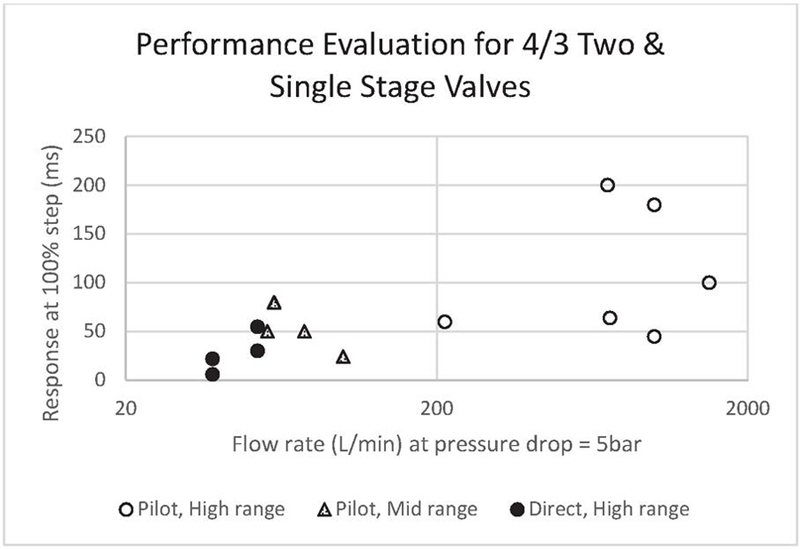
Figure 9 Performance evaluation of two & single stage valves.
➢ Flow values are for specific, different operating conditions.
➢ Response time (Longest: closing or opening) at 100% step is Per metering edge. Some figures were recalculated at the 5 bar value according to .
➢ The last two digits represent the NG part of the German DIN Standard, which relates to port size in metrics.
➢ The “Parker-D3FP-10” & “Parker-D111FP-32” are driven by the patented Voice Coil Drive actuator.
➢ The reader is advised not to take this table as a comparative analysis between different valve manufacturers, given that other consequential features are not mentioned here.
➢ Valve catalogs are open access at manufacturers’ websites.
➢ For the above direct drives valves, the frequency (Hz) at 90 phase shift and 100% signal ranges from 20 to 80 HZ. On the other side, a selective Pilot valve: (Eaton-KBHD-NG10 has 50 HZ, and the larger Eaton-KBHD-NG32 has 40 HZ).
4.2 Miscellaneous Pilot Operated Components
The following literature survey gives a glance at the studies published by fluid power companies:
First, to start with hydraulic motors technology, Diinef has joined forces with Imenco Bauer Hydraulics [130] to launch the world’s first digital high torque low-speed hydraulic motor, with peak power close to 1.4 MW. Each cylinder is provided with two main poppet valves, and each valve is Pilot operated by a 3/2 spool valve. Moreover, a group of researchers from Diinef company, MacGregor company, and the University of Agder, attempted to broaden the usage of digital displacement high torque low-speed motors; the objective was to drive large winches in offshore and maritime applications (150-ton range) by employing fast-acting Pilot valves [131].
Repeatedly, high response timing at high flow rates is critical for various applications. A prototype valve from Eaton looks most promising; the 3/2 Pilot-operated Digital Valve (Q 350 L/min at 5 bar, with mainstage switching time 0.7 ms) was developed to address the mobile market. Such a digital hydraulics valve was implemented on a 22-ton excavator [132], but since published in 2016, the authors could not get any additional updates.
Eaton corporation once more [133] developed a Multistage IMV with pressure and position sensors embedded in each spool (main & Pilot). The valve possesses a fault-tolerant control strategy (Eaton CMA); this technology allows the valve to operate if one of the four sensors fails.
Opposed to the traditional approach, where electromagnetic actuators drive hydraulic valves, Thomas Magnete company [134] implemented a stepper motor that could be used to drive Pilot valves or used to position the main valve spool directly; the steeper motor showed a unique approach to fulfill the requirements of a hydraulic application (10 mm stroke with 300N load at 50 ms response time).
5 Summary, a Peak at Alternative Actuation Systems, and Outlook
5.1 Generic Difficulties in Pilot Operated Valves
Pilot stages typically require an oil pressure of 20 to 30 bar for the components to operate properly [135]. An inadequate source to supply Pilot pressure to hydraulically Piloted valves can reduce system reliability and create hydraulic oscillations [136]. Alternatively stated, Pilot operated valves with internal Pilot supply are easily affected in case of supply pressure variations, especially when there are large supply line volumes between the supply system and the valve-controlled drives [137]. Hence, Pilot operated valves preferred to have an externally supplied stable source. Taken out of context, it is important to recall the fact that there is an ongoing lean toward developing high-force actuators to substitute the requirement for a high-pressure, external Pilot supply circuit [138]. Recently, the IFAS lab at RWTH Aachen University [139] has developed a new electromechanical actuation system that has been tested for valves with a nominal size of NG25, enabling flow rates of up to 600LPM and a fast switching time of only 200 ms at nearly no load; notably, this performance cannot be achieved with all valve types.
Moreover, contamination, oxidation, and viscosity changes of the oil can directly affect the operation of the Pilot stage and, subsequently, the hydraulic system’s controllability and efficiency [140]. Additionally, Pilot valves are usually operated by electric operators, and the output performance depends on their characteristics [134].
Electrohydraulic actuation (Pilot operated valves) is a state-of-the-art design used to control the main valve spool of hydraulic valves. However, as described previously, the valve control depends on the Pilot parameters and is not precise unless a closed-loop control with a position sensor is integrated. Such arrangements present very high hysteresis and need additional stand-alone sensors when precision is requested [141], despite the fact that LVDT technology still has many difficulties detecting displacements in the Pilot stage spool of the proportional valve [142].
Over and above, Pilot valves have more leakage than direct operated valves [143], respond slowly to pressure buildup [144], and are more complex in structure. And as might be expected, Pilot valves tend to have high power losses due to flow passes through bypass orifices [145, 146].
5.2 Innovations and Boundaries of Other Competing Technologies
Developments
The three main actuation systems commonly available are: Traditional centralized hydraulic system, Electro hydrostatic system (EHA) and Electromechanical system (EMA). In order to entirely avoid Pilot operated components, some researchers have chosen to upgrade the last two systems. EMA provides higher resolution [147], uses a single type of energy creating a unified energy system [148], has better controllability [86], and has no leakage. As an alternative, the EHA has a closed cycle architecture, in which the return flow from the actuator goes directly back to the inlet of the pump without using directional control (throttling) valves [149]. Lee et al. provided a numerical comparison between the three systems [150].
On the other hand, the development of the traditional direct valves controlled system was to either reduce the flow forces acting on the spool [151]. Or advance (extend the application range of direct valves to higher values of pressure, flow rate, and stroke) the actuators of the direct-acting traditional valves to displace the need for a Pilot (amplify) stage. Or innovating other high flow rates direct (Pilot-less) valve configuration, such as digital hydraulics at Tampere University [152], Or the development of the energy coupling actuated valve at Purdue University [153].
Limitations
Other technologies have tried to replace Pilot valves; they endeavored to achieve high response, flow rate, and force values while maintaining a reasonable size electric actuator. Unfortunately, they face some challenges. Namely, it was hard to achieve high pressure and large flow simultaneously using HSVs due to the constraints of the valve stroke and magnetic force [154]. Alternatively, piezoelectric actuators were not much better either; even though they have high-speed and high-output force, their stroke is short (small flowrates) [31, 155]. On this account, both of these actuators are recommended to be utilized in the Pilot stages in case of high flow demands. By the same token, Wang et al. proposed an electromechanical converter with double push rods (20N force) to actuate the Pilot stage [156].
The weight is an obstacle too; Scheidl et al. [157] replaced electrically actuated valves with Pilot actuated ones in order to reduce the size and weight of the four used valves. On top of that, there are also heat [158] and noise [9] problems, along with the usage of large solenoids. Interested readers are referred to a review by Tamburrano et al. [159] for additional limitations of direct drive valves.
Add to all of that; nevertheless, there is an ongoing tendency to replace standard valve-controlled hydraulic cylinders with the EMA counterparts; these solutions have low power to weight ratio [160], limited reliability when subjected to unexpected impact forces and overloads. Furthermore, when looking at the peripheral surroundings and working environment, it is not easy to directly transfer these technologies to construction machinery, as discussed comprehensively by Fu et al. [161]. In comparison to valve control, it is challenging for EHA with practical-size motors to achieve a comparable dynamic response at high flow rates and pressure levels, especially to that of servo-proportional valves. In such situations, it is a research trend to explore coupling a permanent magnet synchronous motor (PMSM) with variable-displacement pumps to achieve adequate performance and address thermal dissipation and power electronics challenges [162]. Moreover, in most cases EHA are not economical for complex machines with many drives, such as wheel excavators [163].
5.3 The Last to Say
The paper addressed and categorized Pilot operated hydraulic components, focusing on Pilot operated valves. The publications mentioned earlier make four kinds of contribution: (I) Present a comprehensive definition of Pilot term used in various fluid power fields, (II) Organize massive, scattered, recent publications on Pilot technology, (III) Analyzes the research status and developmental process of such technology; IV) Introduced a modest comparative study to rank Pilot operated valves among other competing technologies.
The article managed to categorize the major challenges in Pilot valves technology, which were either related to flow control, such as: finding alternative methods to Pilot the main stage to improve the valve performance which led to higher valve complexity, attempting to diminish the deadzone effect in Pilot spool valves, keeping the Pilot flow constant in Pilot operated internal displacement-flow feedback valves. On the other side, pressure control was represented briefly as well, for instance: Pressure feedback, optimally designed Pilot relief valves, handling the effect of pressure unloading, economically harvesting the overflow losses in Pilot operated relief valves, the reveres impact effect that happens in check valves at high-pressure values in addition to the usage of check valves in displacement control using an asymmetric cylinder. One challenge that was absent is investigating the sensitivity of Pilot operated valves to fluid properties, as this can result in variations in valve response and accuracy.
As verified earlier (the authors endeavored to collect unbiased, broad articles), hardly any state-of-the-art technologies have been presented during the last six years, and in fact, most of them are updated versions of older studies and proposed applications (mobile & industrial). Looking at the market, not so many novel designs were presented either; seldom advances were shown in the electronic division though. Increasing the environmental regulations against the current available low-efficient hydraulic components, especially for large machinery, might cause a clash with reality. Developing EHA, EMA and direct-drive technologies is an important track, but the power gap is currently very big to catch. Collaboration between manufacturers, R&D labs, and industrial partners to further refine Pilot-operated valves is extremely important.
Acronyms
| Acronym | Description |
| DCV | Directional control valve |
| IMV | Independent Metering Valve |
| LVDT | Linear variable differential transformer |
| PDV | Proportional directional valve |
| PCV | Pressure control valve |
| PDCV | Proportional directional control valve |
| HSV | High-speed switching valves |
Acknowledgements
This work was supported partially by the Ministry of Education in Finland, represented in Tampere university’s Automation Science and Engineering Department. And partially by the Egyptian Cultural Affairs and Missions. Also, the authors would like to express their gratitude to the Reading Research Circle group at Tampere University for their invaluable insights.
References
[1] H. Chase, L.S.C.a.Z., Improvement in valves for bottom of vessels. 1869, Luther S. Chase and Zebina H. Chase: USA. p. 2.
[2] Wanich, A., Improvement in balance-valves. 1871, Alexander Wanich: USA. p. 4.
[3] Command, U.A.M., ENGINEERING DESIGN HANDBOOK. hydraulic fluids. 1976.
[4] Cetinkunt, S., Mechatronics with experiments. 2015: John Wiley & Sons.
[5] Geimer, M., Mobile Working Machines. 2020: SAE International. 470.
[6] Stump, P.M., N. Keller, and A. Vacca, Energy Management of Low-Pressure Systems Utilizing Pump-Unloading Valve and Accumulator. Energies, 2019. 12(23): p. 4423.
[7] EATON, AXISPRO PROPORTIONAL VALVES, in INDUSTRIAL HYDRAULIC VALVES. 2016, EATON. p. 1–22.
[8] Hannifin, P., Pilot Operated Proportional_DC Valve with LVDT. 2014, Parker Hannifin.
[9] Miller, R., M.R. Miller, and H.L. Stewart, Audel pumps and hydraulics. 2004: John Wiley & Sons.
[10] AG, B.R., Hydraulic pilot control unit of sandwich plate design for the remote control of directional valves, pumps, motors, in Pilot control devices. 2006, Bosch Rexroth AG. p. 1–8.
[11] AG, B.R., Hydraulic pilot control units for armrest installation, in Pilot control devices. 2006, Bosch Rexroth AG. p. 1–12.
[12] AG, B.R., Hydraulic remote controls, in Pilot control devices. 2006, Bosch Rexroth AG. p. 1–12.
[13] Bergada, J.M., Fluid power, mathematical design of several components. 2014: Nova Science Publishers, Incorporated.
[14] Lantela, T., Miniature Digital Hydraulic Valve System-Pilot operated design with fast response and high flow capacity. 2018.
[15] Ali, H.H. and R.C. Fales, A review of flow control methods. International Journal of Dynamics and Control, 2021.
[16] Padovani, D., M. Rundo, and G. Altare, The Working Hydraulics of Valve-Controlled Mobile Machines: Classification and Review. Journal of Dynamic Systems, Measurement, and Control, 2020. 142(7).
[17] Inderelst, I.M., I.D. Prust, and M. Siegmund, Electro-hydraulic SWOT-analysis on electro-hydraulic drives in construction machinery, in 12th International Fluid Power Conference. 2020: Dresden.
[18] Eaton-Vickers, Proportional valves_capabilities brochure. 2008, Eaton-Vickers.
[19] Walters, R.B., Hydraulic and electric-hydraulic control systems. 2000: Springer.
[20] AG, B.R., 3/2, 4/2 and 4/3 directional valves, internally pilot operated, externally pilot operated, in Pilot operated directional spool valves. 2008, Bosch Rexroth AG. p. 1–36.
[21] Akers, A., M. Gassman, and R. Smith, Hydraulic power system analysis. 2006: CRC press.
[22] Cundiff, J.S., Fluid Power Circuits and Controls: Fundamentals and Applications. 2001.
[23] Esposito, A., Fluid power with applications, Pearson international edition. 2013: Prentice-Hall International Upper Saddle River.
[24] Rabi, M.G.E.-D.M., Fluid power engineering. 2009: McGraw-Hill Education.
[25] Trinkel, B., Pneumatic and Hydraulic Systems, in Fluid Power eBook – Fluid Power Circuits Explained, M.G.a.R. Schneider, Editor. 2006, Hydraulics & Pneumatics magazine.
[26] Rexroth, B. Directional spool valves, direct operated, with solenoid actuation. 4-WE-6. Available from: https://docs.rs-online.com/af8c/0900766b812c4505.pdf.
[27] Hydac. 2-way Cartridge valves L-CEE and Control cover. [cited 2023]; Available from: https://www.hydac-na.com/wp-content/uploads/Industrial\%20Valves.pdf.
[28] search, E.P. Pilot multistage valves patents survey (2015–2021). 2022 [cited 2022]; Available from: https://worldwide.espacenet.com/patent/
search?f=publications.pd\%3Ain\%3D20150101-20211231\&q=\%28ti\
%20any\%20\%22multistage\%20multi-stages\%20multistages\%20multi-stage\
%20pilot\%22\%20AND\%20ti\%20any\%20\%22valve\%20valves\
%22\%29\%20NOT\%20ctxt\%20any\%20\%22patient\%20air\%20pneumatic\
%20pneumatically\%20fuel\%20servo\%20gas\%20Refrigeration\%20engine\%20injector
\%22\%20AND\%20pd\%20within\%20\%222015-01-01\%3A2021-12-31\%22
\%20AND\%20pd\%20within\%20\%222015-01-01\%3A2021-12-31\%22\&queryLang=en.
[29] Yao, J., et al., Design of a 70 MPa Two-Way Proportional Cartridge Valve for Large-Size Hydraulic Forging Press. Journal of Beijing Institute of Technology, 2020. 29: p. 260–272.
[30] Dong, P., et al. The simulation analysis for cartridge proportional flow valve. in MATEC Web of Conferences. 2016. EDP Sciences.
[31] Han, M., et al., Investigation on the modeling and dynamic characteristics of a fast-response and large-flow water hydraulic proportional cartridge valve. Proceedings of the Institution of Mechanical Engineers, Part C: Journal of Mechanical Engineering Science, 2020: p. 0954406220922860.
[32] Hannifin, P., Servo Proportional Valve, DFplus§Pilot Operated. 2008, Parker Hannifin.
[33] Wang, S., et al., Study on control performance of pilot high-speed switching valve. Advances in Mechanical Engineering, 2017. 9(7): p. 1687814017708908.
[34] Zhong, Q., et al., Investigation into the Independent Metering Control Performance of a Twin Spools Valve with Switching Technology-controlled Pilot Stage. Chinese Journal of Mechanical Engineering, 2021. 34(1): p. 1–17.
[35] Zhao, R., et al., Research on the performance of a novel electro-hydraulic proportional directional valve with position-feedback groove. Proceedings of the Institution of Mechanical Engineers, Part E: Journal of Process Mechanical Engineering, 2021. 235(6): p. 1930–1944.
[36] Zhang, H., et al., Modeling and Dynamic Characteristics of a Novel High-Pressure and Large-Flow Water Hydraulic Proportional Valve. Machines, 2022. 10(1): p. 37.
[37] Yoshida, F., S. Miyakawa, and S. Iio. Research on the Stability of a System Consisting of a Water Hydraulic Control Valve and Cylinder. in Fluid Power Systems Technology. 2016. American Society of Mechanical Engineers.
[38] Han, M., et al. Mathematical Modelling and Multi-Objective Optimization Design of a Large Flow Water Hydraulic Proportional Cartridge Valve. in ASME/BATH 2017 Symposium on Fluid Power and Motion Control. 2017. American Society of Mechanical Engineers Digital Collection.
[39] Han, M., et al., Numerical analysis and optimisation of the flow forces in a water hydraulic proportional cartridge valve for injection system. IEEE Access, 2018. 6: p. 10392–10401.
[40] Liu, X.-y., et al., Research on the dynamic characteristics of seawater hydraulic cartridge-type 4/3 directional valve. Journal of the Brazilian Society of Mechanical Sciences and Engineering, 2018. 40(1): p. 11.
[41] Mitov, A., et al. Analytical Modelling of Hydraulic Proportional Spool Valve Pilot Operated with Switching Micro Valves. in 2021 6th International Symposium on Environment-Friendly Energies and Applications (EFEA). 2021. IEEE.
[42] Danfoss, Steering_OSPE Steering Valve. 2016, Danfoss.
[43] Yin, Y., et al., Reliability analysis of landing gear retraction system influenced by multifactors. Journal of Aircraft, 2016. 53(3): p. 713–724.
[44] Zhang, J., et al., Modeling and experimental validation of the time delay in a pilot operated proportional directional valve. IEEE Access, 2018. 6: p. 30355–30369.
[45] Mobley, R.K., Fluid power dynamics. 1999: Elsevier.
[46] Elsaed, E., M. Abdelaziz, and N.A. Mahmoud, Using a Neural Network to Minimize Pressure Spikes for Binary-coded Digital Flow Control Units. International Journal of Fluid Power, 2019: p. 323–352-323–352.
[47] Lantela, T. and M. Pietola, High-flow rate miniature digital valve system. International Journal of Fluid Power, 2017. 18(3): p. 188–195.
[48] Ketonen, M. and M. Linjama, DIGITAL HYDRAULIC IMV SYSTEM IN AN EXCAVATOR–FIRST RESULTS.
[49] Saleem, S., Pilot operated cartridge valve-Dynamic characteristics measurements for energy efficient operation and application. 2018.
[50] Zardin, B., et al., Design of two-stage On/Off cartridge valves for mobile applications. Energy Procedia, 2017. 126: p. 1123–1130.
[51] Eaton. Proportional directional valves with onboard electronics. 2014; Available from: https://www.eaton.com/us/en-us/catalog/valves/proportional-directional-industrial-hydraulic-valves-with-onboard-electronics.html.
[52] Xu, B., et al., Analysis and compensation for the cascade dead-zones in the proportional control valve. ISA transactions, 2017. 66: p. 393–403.
[53] Xu, B., et al., A dead-band model and its online detection for the pilot stage of a two-stage directional flow control valve. Proceedings of the Institution of Mechanical Engineers, Part C: Journal of Mechanical Engineering Science, 2016. 230(4): p. 639–654.
[54] Zhang, J., et al., Investigation on the dynamic characteristics and control accuracy of a novel proportional directional valve with independently controlled pilot stage. ISA transactions, 2019. 93: p. 218–230.
[55] Lu, Z., et al., Deadzone compensation control based on detection of micro flow rate in pilot stage of proportional directional valve. ISA transactions, 2019. 94: p. 234–245.
[56] Eaton. Eaton CMA Advanced Sectional Mobile Valves. [cited 2023; Available from: https://www.eaton.com/content/dam/eaton/hydraulics/valves/valve-documents/eaton-cma-90-mobile-valve-technical-catalog.pdf.
[57] Danfoss. PVBM – meter-in/meter-out- module. [cited 2023]; Available from: https://www.danfoss.com/en/products/dps/valves-and-actuators/valves/pvg-proportional-valves/pvg-32-proportional-valves/pvbm-valve-modules/\#tab-overview.
[58] Eriksson, B., Control strategy for energy efficient fluid power actuators: Utilizing individual metering. 2007, Linköping University Electronic Press.
[59] Eaton, Valvistor Proportional Flow Control_Cartridge Valves. 2009, Eaton.
[60] EATON, Eaton proportional valve product guide, in proportional valves 2019, EATON.
[61] Parambath, J., Understanding the Concepts of Proportional Valves in Ten Minutes, in Industrial Hydraulic Systems: Theory and Practice. 2017, Universal Publishers.
[62] Eaton-Vickers, Slip-in Cartridge Valve Catalog E-VLSC-MC002-E1 August 2013. 2013, Eaton-Vickers.
[63] Wang, H., et al., A Novel Control Strategy for Pilot Controlled Proportional Flow Valve With Internal Displacement-Flow Feedback. Journal of Dynamic Systems, Measurement, and Control, 2018. 140(11).
[64] Xiong, X. and J. Huang, Performance of a flow control valve with pilot switching valve. Proceedings of the Institution of Mechanical Engineers, Part I: Journal of Systems and Control Engineering, 2018. 232(2): p. 178–194.
[65] Huang, J., et al., Development of a flow control valve with digital flow compensator. Flow Measurement and Instrumentation, 2019. 66: p. 157–169.
[66] Hao, Y., L. Quan, and J. Huang, Research on the performance of electro-hydraulic proportional flow valve controlled by active pilot pump. Proceedings of the Institution of Mechanical Engineers, Part E: Journal of Process Mechanical Engineering, 2017. 231(4): p. 720–731.
[67] Wang, H., et al., Performance Improvement of a Two-Stage Proportional Valve With Internal Hydraulic Position Feedback. Journal of Dynamic Systems, Measurement, and Control, 2021. 143(7): p. 071005.
[68] Hitchcox, A. Check Valves ERV. 2018 [cited 2021]; Available from: https://www.bucherhydraulics.com/47341/Products/Mobile-and-Industrial-Hydraulics/Products/Valves/Flow-preventing-Valves/Pilot-operated-Check-Valves/ERV/index.aspx.
[69] Zhao, J. and L. Liu, Influence of reversing impact load on performance of a two-step unloading pilot-operated check valves. Journal of the Brazilian Society of Mechanical Sciences and Engineering, 2018. 40(6): p. 295.
[70] Liu, L. and P. Yu, Design and Experiment-Based Optimization of High-Flow Hydraulic One-Way Valves. Fluid Dynamics \& Materials Processing, 2020. 16(2): p. 211–224.
[71] Ketelsen, S., et al., Classification and review of pump-controlled differential cylinder drives. Energies, 2019. 12(7): p. 1293.
[72] Zhang, S., S. Li, and T. Minav. Control and Performance Analysis of Variable Speed Pump-Controlled Asymmetric Cylinder Systems under Four-Quadrant Operation. in Actuators. 2020. Multidisciplinary Digital Publishing Institute.
[73] Zhang, S., A. Wu, and F. Dai. Active Disturbance Rejection Control for Double-Pump Direct-Driven Hydraulics. in Multidisciplinary Digital Publishing Institute Proceedings. 2020.
[74] Zhang, S., S. Li, and F. Dai. Integral Sliding Mode Backstepping Control of an Asymmetric Electro-Hydrostatic Actuator Based on Extended State Observer. in Multidisciplinary Digital Publishing Institute Proceedings. 2020.
[75] Çalışkan, H., T. Balkan, and B.E. Platin. A Complete Analysis for Pump Controlled Single Rod Actuators. in Proceedings of the 10th International Fluid Power Conference, Dresden, Germany. 2016.
[76] Jalayeri, E., et al., A throttle-less single-rod hydraulic cylinder positioning system: Design and experimental evaluation. Advances in Mechanical Engineering, 2015. 7(5): p. 1687814015583249.
[77] Gao, Y., et al., Simulation analysis and experiment of variable-displacement asymmetric axial piston pump. Applied Sciences, 2017. 7(4): p. 328.
[78] Wu, W. and C. Yu, Simulation and experimental analysis of hydraulic directional control for displacement controlled system. IEEE Access, 2017. 6: p. 27993–28000.
[79] Sun, Y., et al. Stability study of a pump-controlled circuit for single rod cylinders via the concept of Lyapunov exponents. in Fluid Power Systems Technology. 2017. American Society of Mechanical Engineers.
[80] Imam, A., et al. Improving the Performance of Pump-Controlled Circuits for Single-Rod Actuators. in Actuators. 2019. Multidisciplinary Digital Publishing Institute.
[81] Quan, L., et al. Performance of speed variable asymmetric pump controlled asymmetric hydraulic cylinder. in Proceedings of the 10th JFPS International Symposium on Fluid Power, Fukuoka, Japan. 2017.
[82] Hagen, D. and D. Padovani, A method for smoothly disengaging the load-holding valves of energy-efficient electro-hydraulic systems. 2020.
[83] Lee, D., et al., Development and Control of an Electro-Hydraulic Actuator System for an Exoskeleton Robot. Applied Sciences, 2019. 9(20): p. 4295.
[84] Pedersen, H.C., T.O. Andersen, and M.R. Hansen. Guidelines for Properly Adjusting Pressure Feedback in Systems with Over-Centre Valves. in Fluid Power Systems Technology. 2016. American Society of Mechanical Engineers.
[85] Hagen, D., D. Padovani, and M. Choux. Design and Implementation of Pressure Feedback for Load-Carrying Applications with Position Control. in Proceedings of the Sixteenth Scandinavian International Conference on Fluid Power, Tampere, Finland. 2019.
[86] Hagen, D., D. Padovani, and M. Choux. Guidelines to Select Between Self-Contained Electro-Hydraulic and Electro-Mechanical Cylinders. in 2020 15th IEEE Conference on Industrial Electronics and Applications (ICIEA). 2020. IEEE.
[87] Cheng, M., et al., Dynamic impact of hydraulic systems using pressure feedback for active damping. Applied Mathematical Modelling, 2021. 89: p. 454–469.
[88] Bianchi, R., G.F. Ritelli, and A. Vacca, Payload oscillation reduction in load-handling machines: A frequency-based approach. Proceedings of the Institution of Mechanical Engineers, Part I: Journal of Systems and Control Engineering, 2017. 231(3): p. 199–212.
[89] Liu, J., H. Xie, and H. Yang, Static and dynamic performance improvement of a hydraulic feedback valve for load control by introducing force feedback and compensation orifice. Proceedings of the Institution of Mechanical Engineers, Part C: Journal of Mechanical Engineering Science, 2019. 233(11): p. 3837–3848.
[90] Liu, J., et al., Flow force regulation of the main poppet in a large flow load control valve. Proceedings of the Institution of Mechanical Engineers, Part A: Journal of Power and Energy, 2017. 231(8): p. 706–720.
[91] Liu, J., H. Xie, and H. Yang. Flow Control Performance Investigation of a Load Control Valve Using Modelling Method Directly Based on Irregular Shaped Groove Parameters. in 2019 2nd International Conference of Intelligent Robotic and Control Engineering (IRCE). 2019. IEEE.
[92] Xie, H., C. Wang, and H. Yang, Research on back-pressure compensation characteristics of a pilot-assisted load control valve applied in overrunning load hydraulic systems. Flow Measurement and Instrumentation, 2021. 82: p. 102048.
[93] Pedersen, H.C. and T.O. Andersen, Pressure feedback in fluid power systems—Active damping explained and exemplified. IEEE Transactions on Control Systems Technology, 2017. 26(1): p. 102–113.
[94] Anders, I.P. and M.S.S. Ströbel, A new energy saving load adaptive counterbalance valve. 2016.
[95] Morselli, S., et al. Dynamics of pilot operated pressure relief valves subjected to fast hydraulic transient. in AIP Conference Proceedings. 2019. AIP Publishing LLC.
[96] Hao, Q., et al., Effects of structure parameters on abnormal opening of pilot-operated relief valve under alternating pressure. IEEE Access, 2019. 7: p. 33932–33942.
[97] Hao, Q., et al., Abnormal Opening Mechanism of Pilot-Operated Relief Valve Under Alternating Pressure. IEEE Access, 2019. 7: p. 129709–129718.
[98] Lin, T., et al., Energy regeneration hydraulic system via a relief valve with energy regeneration unit. Applied Sciences, 2017. 7(6): p. 613.
[99] Lin, T., et al., Influence of the energy regeneration unit on pressure characteristics for a proportional relief valve. Proceedings of the Institution of Mechanical Engineers, Part I: Journal of Systems and Control Engineering, 2017. 231(3): p. 189–198.
[100] Li, Z., L. Su, and T. Lin, Overflow Energy Loss Recovery System Based on Hydraulic Motor-Electric Generator. Applied Sciences, 2021. 11(3): p. 941.
[101] Ouyang, T., et al., Dynamic modelling and optimal design of a clutch actuator for heavy-duty automatic transmission considering flow force. Mechanism and Machine Theory, 2020. 145: p. 103716.
[102] Jian, H., et al., Optimization of a pressure control valve for high power automatic transmission considering stability. Mechanical systems and signal processing, 2018. 101: p. 182–196.
[103] Tamburrano, P., et al., A review of electro-hydraulic servovalve research and development. International Journal of Fluid Power, 2018: p. 1–23.
[104] Song, X., C.-S. Wu, and Z. Sun, Design, modeling, and control of a novel automotive transmission clutch actuation system. IEEE/ASME Transactions on Mechatronics, 2011. 17(3): p. 582–587.
[105] Meng, F., et al., System Modeling and Pressure Control of a Clutch Actuator for Heavy-Duty Automatic Transmission Systems. IEEE Transactions on Vehicular Technology, 2016. 65(7).
[106] Fan, X., et al., Fuzzy-type fast terminal sliding-mode controller for pressure control of pilot solenoid valve in automatic transmission. IEEE Access, 2019. 7: p. 122342–122353.
[107] YAMADA, H., et al. PERCEIVED STIMULI IN HYDRAULIC OPERATION LEVER OF CONSTRUCTION MACHINERY. in The 10th International Symposium on Fluid Power, pp. 2B20 (10 pp.). Fukuoka, Japan. 2017.
[108] Mittal, S., D. Aggarwal, and D.K. Saxena, Innovative Design of Hydraulic Actuation System for Operator Fatigue Reduction and Its Optimization, in Advances in Multidisciplinary Analysis and Optimization. 2020, Springer. p. 225–233.
[109] Mittal, S. and R. Singh, A simplified approach towards draft control in hydraulic machines for component/cost reduction. 2019, SAE Technical Paper.
[110] Li, C., et al., Optimization of Multi-Way Valve Structure in Digital Hydraulic System of Loader. Energies, 2021. 14(3): p. 700.
[111] Ji, X., et al., DSmT-based three-layer method using multi-classifier to detect faults in hydraulic systems. Mechanical Systems and Signal Processing, 2021. 153: p. 107513.
[112] Schoppel, G. and T. Deubel. Virtual Engineering in Hydraulic Valve Design. in Proceedings of the 11th International Fluid Power Conference, Aachen, Germany. 2018.
[113] Du, H. An E/H control design for poppet valves in hydraulic systems. in ASME International Mechanical Engineering Congress and Exposition. 2002.
[114] Muller, M.T. and R.C. Fales, Design and analysis of a two-stage poppet valve for flow control. International Journal of Fluid Power, 2008. 9(1): p. 17–26.
[115] Zhang, R., A.G. Alleyne, and E.A. Prasetiawan, Performance limitations of a class of two-stage electro-hydraulic flow valves. International Journal of Fluid Power, 2002. 3(1): p. 47–53.
[116] Liu, W., J.H. Wei, and B. Hu. Analysis and Optimization of a Hydraulic-feedback Proportional Throttlecartridge Valve. in Applied Mechanics and Materials. 2014. Trans Tech Publ.
[117] Luo, Y., System modeling and control design of a two-stage metering poppet-valve system. 2006, University of Missouri–Columbia.
[118] Carpenter, R. and R. Fales. Mixed Sensitivity H-Infinity control design with frequency domain uncertainty modeling for a pilot operated proportional control valve. in Dynamic Systems and Control Conference. 2012. American Society of Mechanical Engineers.
[119] Lisowski, E. and J. Rajda, CFD analysis of pressure loss during flow by hydraulic directional control valve constructed from logic valves. Energy Conversion and Management, 2013. 65: p. 285–291.
[120] Long, Q., et al., A new kind of pilot controlled proportional direction valve with internal flow feedback. Chinese journal of mechanical engineering, 2010. 23(1): p. 60–65.
[121] Winkler, B., A. Ploeckinger, and R. Scheidl, A novel piloted fast switching multi poppet valve. International journal of fluid power, 2010. 11(3): p. 7–14.
[122] Zheng, K.S., et al. Analysis on the Application of High Speed on-Off Valve (HSV) as Pilot Valve. in Applied Mechanics and Materials. 2012. Trans Tech Publ.
[123] Xu, B., et al., Modeling and dynamic characteristics analysis on a three-stage fast-response and large-flow directional valve. Energy conversion and management, 2014. 79: p. 187–199.
[124] Lei, L., Z. Desheng, and Z. Jiyun, Design and Research for the Water Low-pressure Large-flow Pilot-operated Solenoid Valve. Strojniski Vestnik/Journal of Mechanical Engineering, 2014. 60(10).
[125] Liu, W., et al., Hydraulic-feedback proportional valve design for construction machinery. Proceedings of the Institution of Mechanical Engineers, Part C: Journal of Mechanical Engineering Science, 2015. 229(17): p. 3162–3178.
[126] Krettek, J., et al. Evolutionary hardware-in-the-loop optimization of a controller for cascaded hydraulic valves. in 2007 IEEE/ASME international conference on advanced intelligent mechatronics. 2007. IEEE.
[127] Peng, D., et al. Oil pressure characteristic of automatic transmission’s shift control unit and clutch failure analysis. in 2010 International Conference on Computer Application and System Modeling (ICCASM 2010). 2010. IEEE.
[128] André, S., Optimization of valve damping. 2013.
[129] Johnson, J. The importance of frequency response. 1996 [cited 2021]; Available from: https://www.hydraulicspneumatics.com/technologies/hydraulic-valves/article/21885043/the-importance-of-frequency-response.
[130] Lindholdt, P., H.B. Larsen, and A. Diinef. Digital distributor valves in low speed motors-practical approach. in Proc. of The Ninth Workshop on Digital Fluid Power, Aalborg, Denmark. 2017.
[131] Larsen, H.B., et al. Digital hydraulic winch drives. in Fluid Power Systems Technology. 2018. American Society of Mechanical Engineers.
[132] Yuan, Q. and A. Jogada. Architecture, control and nvh development of digital hydraulics for off-highway vehicle applications. in Proceedings of 10th International Fluid Power Conference, Group A. 2016.
[133] Rannow, M. Fail operational controls for an independent metering valve. in 10th International Fluid Power Conference. Dresden: Dresdner Verein zur Förderung der Fluidtechnik eV. 2016.
[134] Ermert, M., Electromechanical actuator concept for the controlled and direct actuation of a hydraulic main stage. 2016.
[135] Hitchcox, A. Smart Actuation of Pumps and Valves. 2015 [cited 2021]; Available from: https://www.hydraulicspneumatics.com/technologies/cylinders-actuators/article/21884723/smart-actuation-of-pumps-and-valves.
[136] Mutlu, M., et al. System Level Performance and Reliability Investigation of Hydraulic Circuits Using Physics Based Models. in Dynamic Systems and Control Conference. 2016. American Society of Mechanical Engineers.
[137] Schmidt, L., et al. Dynamic Analysis and Characterization of Conventional Hydraulic Power Supply Units. in BATH/ASME 2016 Symposium on Fluid Power and Motion Control. 2016. American Society of Mechanical Engineers Digital Collection.
[138] Vonderbank, T. and K. Schmitz. Design of Electromechanical Actuators for Large Sized Valves. in Multidisciplinary Digital Publishing Institute Proceedings. 2020.
[139] Vonderbank, T., P.M.L. Chavez, and K. Schmitz, Direct Actuation of Large Sized Valves by a Hydraulically Relieved Electromechanical Actuation System. International Journal of Fluid Power, 2022: p. 19–52-19–52.
[140] Parr, A., Hydraulics and pneumatics: a technician’s and engineer’s guide. 2011: Elsevier.
[141] Lux, J. and C. Habegger, New generation of intelligent electromechanical valve actuation. 2018: Universitätsbibliothek der RWTH Aachen.
[142] Xu, B., et al., Research and Development of Electro-hydraulic Control Valves Oriented to Industry 4.0: A Review. Chinese Journal of Mechanical Engineering, 2020. 33: p. 1–20.
[143] Xu, X., et al., Modeling and dynamic analysis on the direct operating solenoid valve for improving the performance of the shifting control system. Applied Sciences, 2017. 7(12): p. 1266.
[144] Choi, J., J.H. Ahn, and H.Y. Kim, Modeling the dynamic behavior of a pilot-operated solenoid valve for an ultra-high pressure vessel. Applied Sciences, 2021. 11(5): p. 2329.
[145] Opgenoorth, A., et al., Challenges and possibilities of the integration of electric drives in mobile machinery, in 12th International Fluid Power Conference (IFK). 2020, International Fluid Power Conference: Dresden.
[146] Macpherson, J., et al. Energy Efficient Excavator Hydraulic Systems With Digital Displacement§Pump-Motors and Digital Flow Distribution. in BATH/ASME 2020 Symposium on Fluid Power and Motion Control. 2020. American Society of Mechanical Engineers Digital Collection.
[147] Marani, P., C. Ferrari, and M. Ruggeri. Flow Reactions Prediction in Roto-Translating Valve Through CFD Simulations. in Fluid Power Systems Technology. 2016. American Society of Mechanical Engineers.
[148] Ismagilov, F., V. Vavilov, and I. Sayakhov. High-Torque Motor for a Gearless Electromechanical Actuator. in 2019 26th International Workshop on Electric Drives: Improvement in Efficiency of Electric Drives (IWED). 2019. IEEE.
[149] Alle, N., et al., Review on electro hydrostatic actuator for flight control. International Journal of Fluid Power, 2016. 17(2): p. 125–145.
[150] Lee, W., et al., A review of integrated motor drive and wide-bandgap power electronics for high-performance electro-hydrostatic actuators. IEEE transactions on transportation electrification, 2018. 4(3): p. 684–693.
[151] Amirante, R., E. Distaso, and P. Tamburrano, Sliding spool design for reducing the actuation forces in direct operated proportional directional valves: Experimental validation. Energy Conversion and Management, 2016. 119: p. 399–410.
[152] Ketonen, M. and M. Linjama. High flowrate digital hydraulic valve system. in Proc. of The Ninth Workshop on Digital Fluid Power, Aalborg, Denmark. 2017.
[153] Garrity, J., F. Breidi, and J. Lumkes. Design of a high performance energy coupling actuated valve (ECAV). in Proceedings of the 10th international fluid power conference. 2016.
[154] Zhang, Q., et al., Review and development trend of digital hydraulic technology. Applied Sciences, 2020. 10(2): p. 579.
[155] Angelov, I., et al. Implementation of Piezoelectric Actuators for Pilot Valve of High Response Hydraulic Servo Valve. in International Conference on Future Access Enablers of Ubiquitous and Intelligent Infrastructures. 2019. Springer.
[156] Wang, X., et al., Dynamic and Static Characteristics of Double Push Rods Electromechanical Converter. Chinese Journal of Mechanical Engineering, 2019. 32(1): p. 1–11.
[157] Scheidl, R. and S. Mittlböck. A Hydraulic Piloting Concept of a Digital Cylinder Drive for Exoskeletons. in Fluid Power Systems Technology. 2018. American Society of Mechanical Engineers.
[158] Kann, S.v. Flow control valves; the most used accessory in flow control. 2019; Available from: https://www.bronkhorst.com/int/blog-1/flow-control-valves-the-most-used-accessory-in-flow-control/.
[159] Tamburrano, P., et al., A review of direct drive proportional electrohydraulic spool valves: industrial state-of-the-art and research advancements. Journal of Dynamic Systems, Measurement, and Control, 2019. 141(2).
[160] Padovani, D., et al., A self-contained electro-hydraulic cylinder with passive load-holding capability. Energies, 2019. 12(2): p. 292.
[161] Fu, S., L. Wang, and T. Lin, Control of electric drive powertrain based on variable speed control in construction machinery. Automation in Construction, 2020. 119: p. 103281.
[162] Guo, T., et al. A Preliminary Design Method of High-Power Electro-Hydrostatic Actuators Considering Design Robustness. in Actuators. 2022. MDPI.
[163] REINERTZ, O. and K. SCHMITZ, Fluid Power Innovations–On track for Future Challenges.
Biographies

Essam Elsaed received his M.Sc. at Ain Shams University, Egypt, in 2018, Mechanical Engineering Department. Currently, he is a PhD student at the Automation Technology and Mechanical Engineering Unit, Tampere University, Finland. Alternative email: essam.elsaed1@gmail.com

Matti Linjama obtained a D Tech degree at Tampere University of Technology, Finland, in 1998. Currently, he is an adjunct professor at the Automation Technology and Mechanical Engineering Unit, Tampere University. He started the study of digital hydraulics in 2000 and has focused on the topic since then. Currently, he is a leader of the digital hydraulics research group, and his professional interests include the study of hydraulic systems with high performance and energy efficiency.
International Journal of Fluid Power, Vol. 24_4, 683–724.
doi: 10.13052/ijfp1439-9776.2443
© 2023 River Publishers