Effect of Blowing Ratio on Turbine Blade Air Film Cooling Under Different Engine Conditions
Miao Gong*, Cunyuan Ma, Annan He, Wen Huang and Huaijin Yan
Institute of Aviation Engineering, Civil Aviation University of China,
Tianjin, China
E-mail: mgong@cauc.edu.cn
*Corresponding Author
Received 19 April 2022; Accepted 04 July 2022; Publication 12 June 2023
Abstract
Under different working conditions of the aeroengine, the rotating speed of the turbine blades is diverse, and this causes the high-temperature gas mainstream to impact the turbine blades at disparate angles of attack. In order to explore the film cooling mechanism of the pressure surface and suction surface of aeroengine turbine blade at unusual speed, a 3D model of the turbine blades and internal runners is constructed, which refers to Pratt & Whitney PW4084 primary HPT blade. In this model, the high-temperature gas mainstream is set to attack the turbine blades through three distinct angles, the turbine blade air film cooling model is established, and the numerical simulation is conducted at the different blowing ratios. The results showed that the angle of impact (rotational speed) is the key factor affecting the cooling efficiency of the blade. The cooling effect of the suction surface is the best under the positive attack, however, the cooling effect of the pressure surface under the negative attack angle is the first-rate. With the increase of the speed, the surface temperature of the top and tail of the blade pressure surface will gradually decrease, and as the speed reduces, the surface temperature of the lower part of the suction surface of the blade will slightly increase. Finally, under three different attack angles, the cooling efficiency of the air film on the surface of the blade will augment with the increase of the blowing ratio.
Keywords: Turbine blades, film cooling, numerical simulation, incidence angle, rotation, blowing ratio.
1 Introduction
In the design of modern advanced aero-engines, the turbine inlet temperature T3* is constantly increased to obtain higher engine thrust. According to calculation, when T3 is increased by 55 K, engine thrust can be increased by 10% under the same engine size condition [1], which results in the working environment of turbine blades exceeding its heat tolerance limit. This will greatly reduce the reliability and life of turbine blades. Film cooling is one of the most classical and effective methods to protect blades from the influence of high temperature gas. The principle of the turbine blade film cooling are cooling air flow through the holes in the blade surface to surface of blade, under the action of the pressure of the high temperature gas parcel after blade surface, a layer of cooling gas film with low temperature is formed on the surface of turbine blade, Separate the direct contact between high mainstream gas and turbine blade, reduce the heat exchange rate between turbine blades and gas, the blade surface is cooled and protected [2]. Goldstein [3] proposed the basic understanding of gas film cooling and gave two evaluation indexes: cooling efficiency and heat transfer coefficient.
At present, about the turbine blade film cooling are mainly concentrated in the static condition, Hong-Li Zhao [4] studied in static state, such as turbulence and blowing ratio for the influence of the blade suction surface film cooling efficiency, results show that the cooling efficiency decreases with increasing blow ratio, in the situation of small flow, gas film cooling efficiency decreases with increasing the mainstream turbulence degrees, in the situation of big blowing ratio, The film cooling efficiency increases with the increase of turbulence. Robert et al. [5] compared and analyzed the temperature field and velocity field at the downstream of the hole under different blowing ratios and turbulent conditions, and pointed out that the thermal field with low turbulent intensity showed the initial attachment of coolant jet, and the phenomenon of cold air delayed separation from the wall appeared at the position of X/D 30. However, this phenomenon did not occur under the condition of high stagnation. Li Hai-wang et al. [6] studied the effects of air blowing ratio, density ratio and turbulence degree on the cooling efficiency of the blade leading edge air film under the rotating state by experimental method. Under each air blowing ratio, the efficiency value is monotonous with the increase of the aperture. increase; in the case of the two film hole diameters, the area efficiency value increases monotonically with the increase of the blowing ratio; under the same blowing ratio, the average film cooling efficiency produced by different densities of coolant gas increases with the increase of the mainstream Reynolds number. large and increased. The study of Ahn et al. [7] showed that at 2400 rpm, the coolant from the outlet of the central discharge hole of the leading edge was deflected toward the suction surface; at 2500 and 3000 rpm, it was deflected in the direction of the span and pressure surfaces. Li et al. [8] used TCL technology to study the effect of blowing ratio on the suction and pressure surfaces of rotating blades. Higher-density coolants can provide a higher level of film performance on the suction and pressure surfaces; as the blowing ratio increases, The film coverage increases monotonically on the pressure side and shows a parabolic trend on the suction side. Li et al. [9, 10] studied the influence of mainstream Reynolds number, rotational speed and blowing ratio on rotating and twisted blades. The results show that rotational speed plays an indispensable role in the film cooling efficiency of the leading edge. When the blowing ratio is constant, Both the mainstream Reynolds number and the rotational speed will increase the regional average film cooling efficiency.
The actual working condition of the turbine blade is in rotation state, according to the study of Schoberiri et al. [11, 12] and with reference to turbine aerodynamics, when the turbine runs at a lower speed, the main flow impinges on the leading edge of the blade at a positive Angle of attack and causes the stagnation line to move to the pressure side, and part of the jet flows out of the pressure outlet of the leading edge deviates to the suction side. Similarly, when the turbine runs at a high speed, the main flow impinges on the leading edge of the blade at a negative angle of attack, making the stagnation line move to the pressure side and the jet flow deviates to the pressure side. At present, the film cooling of turbine blades mainly focuses on static conditions, therefore, in view of different speed conditions, this paper establishes the gas film cooling model of high temperature gas mainstream impacting turbine blades at three angles: positive incidence angle, zero incidence angle and negative incidence angle, and analyzes the effects of impact Angle of attack and blow ratio on the gas film cooling characteristics of turbine blade leading edge, suction surface and pressure surface.
2 Blade Geometry and Numerical Modeling
2.1 Blade Geometric Model
In this paper, the turbine blade geometric model is established in two stages [13]. First, the profile of turbine blade section is established, which is composed of four surfaces: leading edge, trailing edge, suction surface and pressure surface, secondly, each blade shape is superimposed radially to obtain the blade model. The three dimensional blade model is established by professional blade modeling software Autoblade. In this paper, five sections of blade root (S1), 1/4 root (S2), average radius (S3), 3/4 tip (S4), and tip (S5) are selected to construct the blade curve. The edge lines are radially stacked, as shown in Figure 1(a). The Bezier curves of the suction surface and the pressure surface are constructed based on the mid-arc line [14]. The construction method is shown in Figure 1(b).
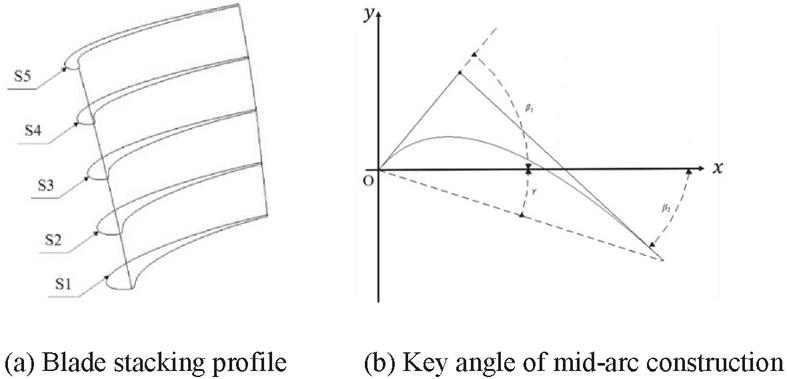
Figure 1 Blade profile and structural key angle.
The main structural parameters of the mid-arc are shown in Table 1. In the table, is the radius of the leading edge, is the radius of the trailing edge, and is the wedge angle of the trailing edge. Counterclockwise is positive. In the figure, and are respectively complementary to the inlet airflow angle, outlet airflow angle, and installation angle in the literature, Blade height is 70 mm. Figure 2 shows the 3D model of the blade.
Table 1 The parameter values of the arc construction angle
| Parameter Section | S1 | S2 | S3 | S4 | S5 |
| 50 | 56.25 | 62.5 | 68.75 | 75 | |
| 43 | 44.25 | 45.5 | 46.75 | 48 | |
| 18 | 21 | 24 | 27 | 30 | |
| 1 | 1 | 0.9 | 0.8 | 0.8 | |
| 0.5 | 0.5 | 0.5 | 0.5 | 0.5 | |
| 4 | 3.5 | 3 | 2.5 | 2 |

Figure 2 Three dimensional model of blade.
Design with reference to the internal flow channel shape of the first-stage HPT blade of Pratt & Whitney PW4084 aircraft engine, as shown in Figure 3. In this study, four flow channels were set up, respectively numbered C1, C2, C3, C4 and C5, and the gas film holes were arranged on the surface of the blade to simulate the simulation.
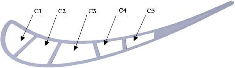
Figure 3 Blade geometric model runner.
As for the arrangement of air film holes on the blade surface, the air film holes are arranged on the outer wall of C1–C5 flow passage, the layout of transverse exhaust film holes at the top of the blade and the narrow slot cooling at the tail of the blade is not considered temporarily. Six rows of air film holes are arranged on the pressure surface, called Ps1, Ps2, Ps3, Ps4, Ps5 and Ps6, and three rows of air film holes are arranged on the suction surface, called Ss1, Ss2 and Ss3, with a total of 155 air film holes, as shown in Figure 4. The shape of the air film hole is cylindrical, and the aperture is set as mm. Due to the different angle of the air film hole, the performance on the blade is different.
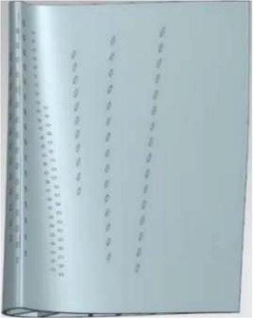
Figure 4 Air film hole location.
The gas film hole is defined by the parenthetical position, which is represented by the dimensionless flow distance lc on the blade pressure surface and suction surface and the dimensionless radial distance Sc on the blade. Among them , the l represents the transverse distance of the blade from the center line of the leading edge, Positive and negative values represent the dimensionless distances from the pressure surface and suction surface to the center line of the leading edge of the blade respectively. , the represents the radial distance from the lower boundary of the blade. and Constitute a two-dimensional coordinate system to represent the distribution of gas film holes on the blade surface, as showed in Figure 5.
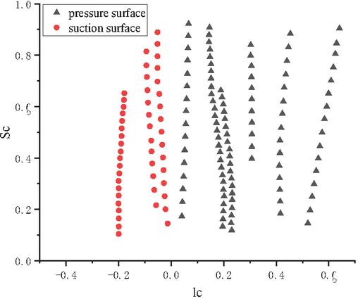
Figure 5 Dimensionless position of gas film hole.
2.2 The Numerical Model
2.2.1 Model and parameter definition
The flow inside and outside the blade is simulated as incompressible turbulent flow, and the conjugate heat transfer interface of the fluid-solid heat transfer module is used to combine the heat equation and turbulence in numerical simulation. The turbulence model adopts the SST model, which is widely used and high precision in near wall free flow, and can combine model and model. It is very suitable for turbomachinery applications [15]. The governing equations conjugate heat transfer interface and non-isothermal flow include:
The expression of the momentum equation for continuity:
| (1) | |
In the formula: -Density , u-Velocity vector , p-Pressure , -Dynamic viscosity , F-Physical strength vector .
The heat equation for the fluid domain:
| (3) |
In the formula: -Specific Heat Capacity At Constant Pressure , -Absolute temperature , -Conduction heat flux , -Radiant heat flux , -Strain rate tensor , -Contains other heat sources .
Heat equations for solid domains and physical interfaces:
| (4) |
In the formula: -Thermoelastic Damped Heat Source .
The blow ratio is defined as , where is the jet density, is the jet velocity, is the mainstream density, is the mainstream velocity; The film cooling efficiency is defined as , where is the mainstream temperature, is the blade adiabatic surface temperature, is the jet temperature; Density ratio .
2.2.2 Computing domains and meshing
The computational domain consists of blade, internal flow channel, main flow channel and gas film hole, In order to simulate the real working condition of turbine blades, two blades are selected to achieve the flow state of the real gas main channel, as shown in Figure 6. Two blades were marked B1 and B2 respectively. During the analysis of numerical simulation results, the surfaces on both sides of the flow passage between the two blades were selected for analysis, that is, the pressure surface of B1 blade and the suction surface of B2 blade were analyzed, In order to get closer to the working state of blade pressure surface and suction surface under the actual working condition of turbine blade.
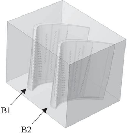
Figure 6 Calculation domain of numerical model.
The numerical model computing grid is generated by using the simulation computing software grid generator. The grid is selected as tetrahedral grid, and the grid size is reasonably divided under the requirement of ensuring the calculation accuracy. Set a suitable growth rate by adjusting the mesh size range of the domain, The minimum mesh size is 0.058 mm, 2.19 10 tetrahedral elements, 3.16 10 triangular elements, 2.5 10 edge elements, 1430 point elements, and the total number of computational domain meshes is 2.19 10, the mesh quality is measured by skewness, and the average element quality of all meshes is 0.6468, and the grid construction results are shown in Figure 7.
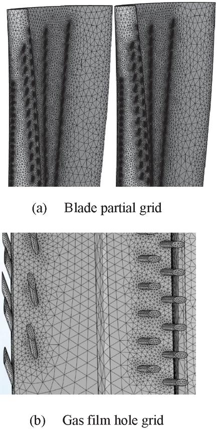
Figure 7 Local mesh generation of numerical modeling.
Figure 8 shows the blade spanwise air film cooling efficiency under the condition of zero attack angle impact, M 1.5, and the number of meshes are 1.85 10, 2.19 10 and 2.54 10, respectively Comparing the figures, the calculation results of three different grid numbers differ by less than 0.8%. After comprehensive consideration, a model with a grid number of 2.19 10 was selected for the final calculation.
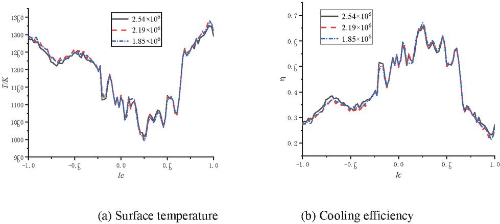
Figure 8 Surface temperature and cooling efficiency with different mesh numbers.
2.2.3 Boundary conditions
In the calculation domain, the interface between the main flow channel and the blade is set as an adiabatic non-slip boundary condition to realize the heat exchange between the fluid and the blade. The wall surfaces of the main flow passage of the blade except the inlet and outlet are set as adiabatic non-slip boundary conditions. Both the main flow and the coolant flow adopt the SST turbulence model. The mainstream turbulence degree is set to 10%, the turbulence intensity of the coolant is 5%, and the typical blowing ratio of a turbine engine is about 0.5–2.0. In this paper, the air blowing ratio M is set to be increased from 0.50 to 2.00 at intervals of 0.50, which are 0.50, 1.00, 1.50, and 2.00, respectively. The initial conditions and boundary conditions are summarized as follows: Main flow to jet density ratio ; outlets are set to equal pressure outlets, and the pressure is constant at pa; the high temperature main flow inlet temperature is set to K, the flow rate is set to m/s, and the cooling channel inlet is set. The temperature is set to and the speed of the internal flow channel of the blade is calculated by the blowing ratio. In order to ensure that the outflow gas of all cooling film holes has a similar blowing ratio, the inlet speed of the C1–C5 flow channel needs to be calculated separately.
3 Results and Discussion
3.1 Influence of Mainstream Incident Angle of Attack (Rotation Speed)
After learning of the relevant knowledge of turbine aerodynamics and referring to scholarly et al. [11, 12]. When the turbine blade operates at a lower speed, the gas mainstream impacts the leading edge of the blade at a positive incidence angle and moves the stagnation line to the pressure side, Similarly, when the turbine blade runs at high speed, the mainstream impacts the leading edge of the blade at a negative incidence angle, causing the stagnation line to move to the pressure side, This phenomenon can be explained in Figure 9.
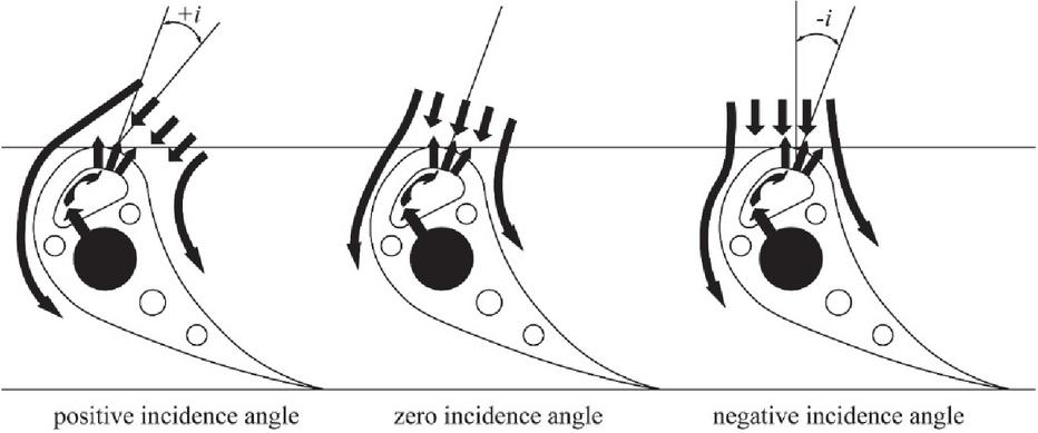
Figure 9 Mainstream impact angle under different rotating speeds (angle of attack) [16].
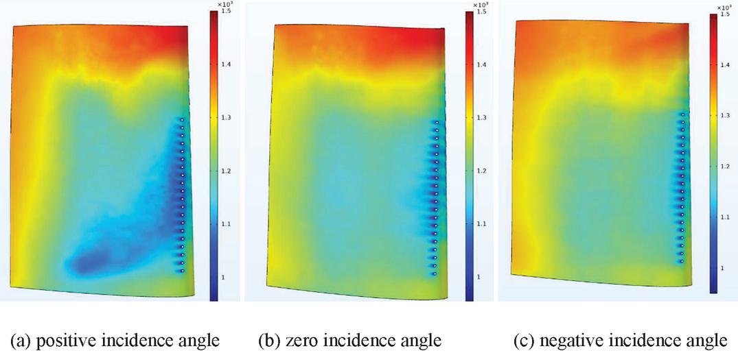
Figure 10 Temperature of suction surface.
In order to study the influence of incident angle of attack (rotational speed), the blowing ratio is set in this study. By changing the angle of air flow incident on the leading edge of the blade, the leading edge of the blade is impacted at positive angle of attack, zero angle of attack and negative angle of attack respectively, The surface temperature distribution nephogram of blade B1 pressure surface and B2 suction surface is shown in Figures 10 and 11.

Figure 11 Temperature of pressure surface.
As showed in Figure 10, when the rotating speed is low, the mainstream impacts the leading edge of the blade at a positive incidence angle. At this time, the stagnation line is biased to the side of the pressure surface, so that the cooling fluid flowing out of the leading edge film hole deflects towards the suction side. As a result, most of the surface temperature of the suction surface under the impact of positive angle of attack is lower than that under the impact of negative angle of attack, it is particularly obvious near the suction side row hole S3. Compared with the negative incidence angle, the deflection of cooling fluid to the downstream of the blade is more obvious under the impact of positive incidence angle, So that the temperature of the lower half of the suction surface is lower than that of the lower half when impacted by other angles of attack, This benefits from the fact that the outflow agent from the film hole at the leading edge of the blade tends to the suction side and deflects downward, however, it will also make the tail surface temperature slightly higher than the blade tail surface temperature under zero angle of attack impact. When the rotating speed increases gradually, the stagnation line will be located in the leading edge film hole area, so that the cooling fluid flows to the pressure side and suction side respectively, Compared with the positive and negative incidence angle, the surface temperature and gas film coverage effect of pressure surface and suction surface are more uniform at zero incidence angle. As shown in Figure 11, when the rotating speed is high, the mainstream impacts the leading edge of the blade at a negative incidence angle, and the stagnation line will be biased to one side of the suction surface, The cooling fluid flowing out of the leading edge film hole faces the pressure surface, this makes the surface temperature and gas film coverage effect of the pressure surface under the impact of negative incidence angle better than that under the impact of positive angle of attack, On the pressure surface, it is obvious that the cooling flux has an upward deflection trend, and the upward deflection trend is more obvious with the increase of rotating speed. The temperature at the top of the blade decreases gradually, which benefits from the fact that the outflow agent from the film hole at the leading edge of the blade is biased to the pressure side. With the increase of rotating speed, that is, in the process of changing from positive incidence angle to negative incidence angle, the surface temperature at the top and tail of the pressure surface will gradually decrease; As the speed decreases, that is, in the process of gradually changing from negative incidence angle to positive incidence angle, the temperature at the lower part of the suction surface will gradually increase.
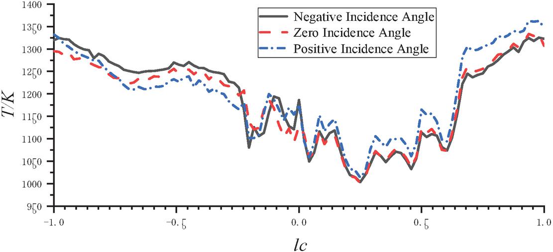
Figure 12 Spanwise surface average temperature at different angles of attack.
As shown in the figure, Figure 12 shows the average temperature curve of blade spanwise surface under the condition of impact blade at three different incidence angle when . The abscissa is the dimensionless slantwise position of the blade with the leading edge point of the blade at zero point, and the ordinate is the film cooling efficiency . It can be seen from the figure that the blade surface temperature fluctuates with the arrangement position of blade film holes. In the area with film holes, the surface temperature will have an obvious regional minimum; In the case of three incidence angle impact, the area where the temperature of the pressure surface is lower than 1150 k is significantly more than that of the suction surface; In the range of pressure surface and leading edge (0.1,1.0), the blade surface temperature under positive incidence angle impact is significantly higher than that under negative incidence angle impact, while the temperature in the range of one side of suction surface (1.0,0.24) is significantly lower than that under negative incidence angle impact, and there is little difference in the surface temperature under the three incidence angles impact conditions of leading edge (0.24,0.1), This is because the temperature near the gas film hole S3 is relatively close due to the existence of the gas film hole S3. Therefore, with the increase of rotating speed, that is, in the process of changing from positive incidence angle to negative incidence angle, the average temperature of suction surface decreases significantly, the average temperature in the leading edge area of blade does not change significantly, while the average temperature of pressure surface increases gradually. Therefore, the angle of attack (rotating speed) is the key factor affecting the effect of film cooling.
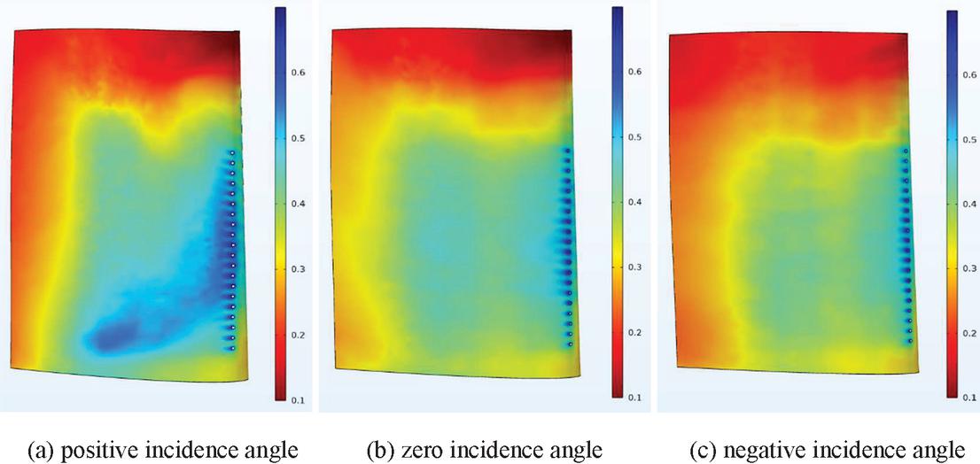
Figure 13 Cooling efficiency of suction surface.
As shown in Figure 13, when the rotating speed is low, the mainstream impacts the leading edge of the blade at a positive incidence angle. At this time, the stagnation line is biased to one side of the pressure surface, so that the cooling fluid flowing out of the leading edge film hole deflects towards the suction side, which makes the cooling effect of the suction surface under the impact of positive incidence angle better than that under the impact of negative incidence angle. When the rotating speed increases gradually, the stagnation line will be located in the leading edge film hole area, making the cooling fluid flow to the pressure side and suction side respectively. Compared with the positive and negative incidence angle, the cooling efficiency and film coverage effect of the pressure surface and suction surface at zero incidence angle are more uniform.
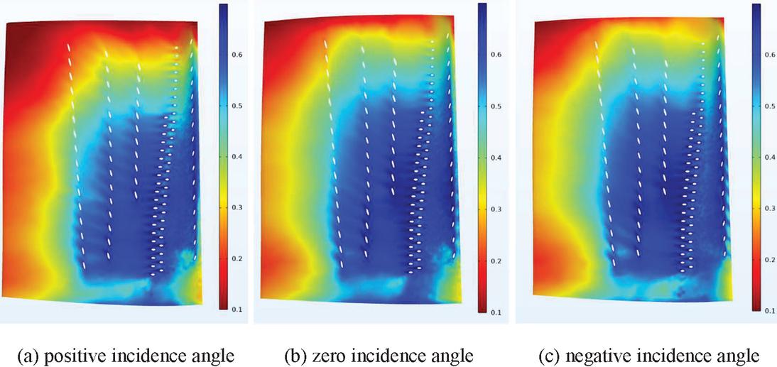
Figure 14 Cooling efficiency of pressure surface.
As showed in Figure 14, when the rotating speed is high, the mainstream impacts the leading edge of the blade at a negative incidence angle. At this time, the stagnation line will be biased to one side of the suction surface, and the cooling fluid flowing out of the leading edge film hole faces the pressure surface, which makes the cooling effect of the pressure surface under the impact of negative incidence angle better than that of the suction surface under the impact of positive incidence angle. Therefore, the incidence angle (rotational speed) is the key factor affecting the film cooling effect.
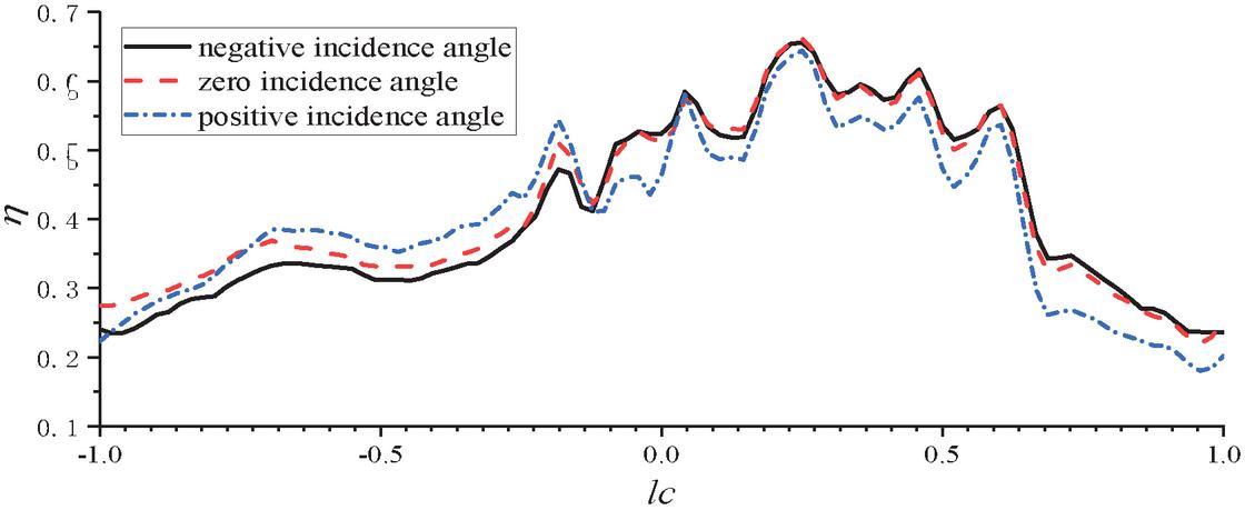
Figure 15 Spanwise average film cooling efficiency at different angles of attack.
Figure 15 is the curve of blade spanwise average film cooling efficiency under the condition of impacting blades at three different incidence angle when . The abscissa is the dimensionless slantwise position of the blade with the leading edge point of the blade as the zero point, and the ordinate is the film cooling efficiency . It can be seen from the figure that at low speed, the gas mainstream impacts the blade at a positive angle of attack, the film cooling efficiency provided by the pressure surface section and the leading edge section (0.24,1.0) is the lowest. For higher speeds (negative angles of attack), the stagnation line is located on the pressure side, and the cooling fluid flowing out of the leading edge film hole will tend to one side of the suction surface. Therefore, the film cooling efficiency provided by the suction surface section (1.0,0.24) is the highest under the negative incidence angle. When the mainstream impacts the blade at zero incidence angle, the stagnation line is located at the leading edge film hole, so that the cooling fluid flowing out of the leading edge film hole flows to the pressure surface and suction surface respectively. Therefore, the cooling efficiency under zero incidence angle impact is better than that under negative incidence angle impact at the pressure surface and part of the leading edge (0.24,1.0), however, the cooling efficiency under the impact of negative incidence angle (1.0,0.24) on one side of the suction surface is better than that under the impact of zero incidence angle. When the mainstream impacts the blade at a negative incidence angle, the stagnation line is located on one side of the suction surface, and the cooling fluid flowing out of the leading edge film hole will be biased to the side of the pressure surface. Therefore, the cooling efficiency under the negative incidence angle impact in the pressure surface section and the leading edge section (0.24,1.0) is better than that under the zero negative incidence angle impact, however, the film cooling efficiency is the lowest under the impact of positive incidence angle (1.0,0.24) on one side of the suction surface.
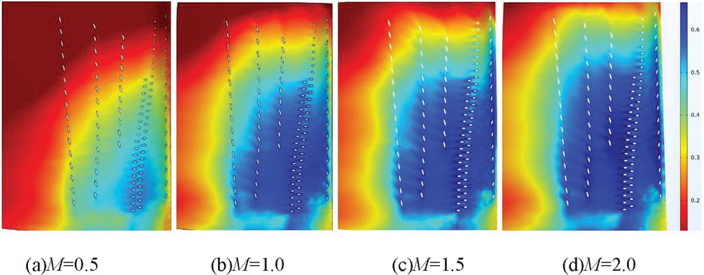
Figure 16 Film cooling efficiency of pressure surface.
3.2 The Effect of Blower Ratio
Figure 16 shows the cloud diagram of film cooling efficiency distribution on the pressure surface under different blowing ratios under the impact of zero incidence angle. With the increase of blowing ratio, the film cooling efficiency of pressure surface increases the area of is growing [17].
Figure 17 shows the cloud diagram of film cooling efficiency distribution on suction surface under different blowing ratios under zero incidence angle impact. With the increase of blowing ratio, the region of film cooling efficiency on the suction surface becomes larger. With the increase of blowing ratio, the cooling fluid flowing out of the film hole can extend further downstream on the suction surface, reflecting that the film extension performance of the suction surface is better. This is because the suction surface is a convex curvature surface, and the cooling flux is easy to separate from the blade surface after flowing out. When the blowing ratio is low, the cooling flux is mixed with the main stream to raise the temperature, resulting in poor cooling effect and small coverage area. With the increase of blowing ratio, the flow rate and flow rate of cooling flux increase, and a small part is mixed with the main stream. Most of the remaining cooling flux can continue to adhere to the blade surface to cool the blade.
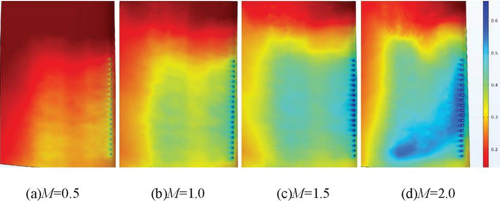
Figure 17 Film cooling efficiency of suction surface.
Figure 18 shows the blade slantwise average film cooling efficiency curve under the impact of zero angle of attack and different blowing ratios. The abscissa is the dimensionless span wise position of the blade with the leading edge point of the blade as zero, and the ordinate is the film cooling efficiency . Under different blowing ratios, the film cooling efficiency on the blade surface fluctuates with the arrangement position of the film holes, and increases with the increase of blowing ratio. In the range of M 0.5 to M 1.5, the film cooling efficiency increases sharply with the increase of blowing ratio, while the increase of film cooling efficiency in the range of M 1.5 to M 2 is relatively small, so the blowing ratio of M 1.5 has the most severe impact on the blade surface cooling efficiency.
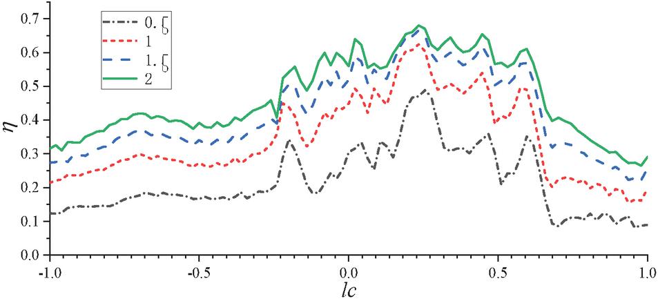
Figure 18 Span-average film cooling efficiency at different blowing ratios at zero incidence angle.
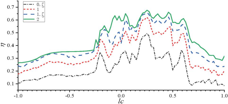
Figure 19 Span-average film cooling efficiency at different blowing ratios at negative incidence angle.
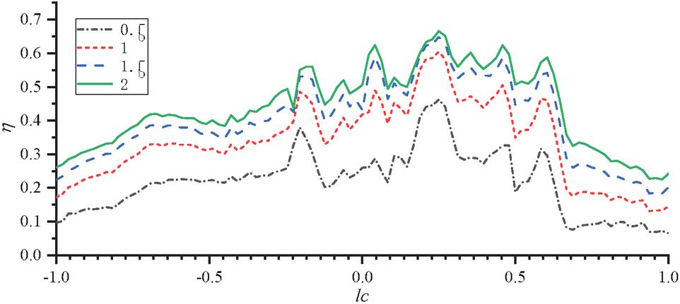
Figure 20 Span-average film cooling efficiency at different blowing ratios at positive incidence angle.
Figures 19 and 20 show the blade span wise average film cooling efficiency curves under different blowing ratios under the impact of negative incidence angle and positive incidence angle respectively. The abscissa is the dimensionless span wise position LC of the blade with the leading edge point of the blade as the 0 point, and the ordinate is the film cooling efficiency . It can be seen from the figure that under impact conditions of negative incidence angle and positive incidence angle, the film cooling effect on the blade surface increases with the increase of blowing ratio.
4 Conclusions
Under conditions of negative incidence angle, zero incidence angle and positive incidence angle and different blowing ratio, 9 rows of film holes were arranged to simulate the film cooling of turbine blades. The effects of different incidence angle and blowing ratio on film cooling are compared through numerical simulation. The main results are as follows:
(1) With the increase of rotating speed. The attack angle of high-temperature gas mainstream impact blade changes from positive incidence angle to zero incidence angle and finally to negative incidence angle. The cooling efficiency of the suction surface is the best under the condition of positive incidence angle impact, and the cooling efficiency of the pressure surface is the best under the condition of negative incidence angle impact. Film cooling efficiency is relatively average under the condition of zero attack angle impact. Incidence angle (speed) of gas impinging blade is the key factor affecting the film cooling efficiency.
(2) With the increase of rotating speed, that is, in the process of changing from positive incidence angle to negative incidence angle, the surface temperature at the top and tail of the pressure surface will gradually decrease; As the speed decreases, that is, in the process of gradually changing from negative incidence angle to positive incidence angle, the temperature at the lower part of the suction surface will gradually increase.
(3) For all incidence angle, the span wise average film cooling effect of turbine blade surface increases with the increase of blowing ratio. The increase is more intense in the range of (0.5,1.5).
Acknowledgment
The author acknowledgment the financial support of the open fund of provincial and ministerial scientific research institutions of Civil Aviation University of China (No. tacstec2022002).
References
[1] Ni M, Zhu H R Qiu Y, et al. Review onCooling Technology of Aeroengine Turbine Blades[J]. Gas Turbine Technology, 2005, 18(4): 10. DOI: https://doi.rog/10.16120/j.cnki.issn1009-2889.2005.04.006.
[2] Zhang Y, Wen Z, Pei H, et al. Equivalent model of close-packed film cooling holes in nickel-based single crystal cooled blade based on crystallographic theory[J]. Chinese Journal of Aeronautics, 2019, 32(04): 73–84. DOI: https://doi.org/10.1016/j.cja.2019.01.007.
[3] Faghri A, Yaghoubi M A. Advances in Heat Transfer[M]. Academic Press, 1972.
[4] Zhao H L, Lai Y C, Wei K et al. Film Cooling Characteristics of the Suction Surface of a High Pressure Turbine Rotor Blade [J]. Chinese Hydraulic and Pneumatic, 2021(2): 7. DOI: https://doi.rog/10.11832/j.issn.1000-4858.2021.02.024.
[5] Schroeder R P, Thole K A. Thermal Field Measurements for a Shaped Hole at Low and High Freestream Turbulence Intensity[C]// ASME Turbo Expo 2016: Turbomachinery Technical Conference and Exposition. 2016. DOI: https://doi.rog/10.1115/1.4034798.
[6] Li H W, Zhang D W, Han F, et al. Experimental investigation on the effect of hole diameter on the leading edge region film cooling of a twist turbine blade under rotation conditions[J]. Applied Thermal Engineering, 2021, 184(4):116386. DOI: https://doi.rog/10.1016/j.applthermaleng.2020.116386.
[7] Ahn J, Schobeiri M T, Han J C, et al. Effect of rotation on leading edge region film cooling of a gas turbine blade with three rows of film cooling holes[J]. International Journal of Heat & Mass Transfer, 2007, 50(1/2):15–25. DOI: https://doi.rog/10.1016/j.ijheatmasstransfer.2006.06.028.
[8] Li G, Zhu J, Deng H, et al. Experimental investigation of rotating film cooling performance in a low speed 1.5-stage turbine[J]. International Journal of Heat & Mass Transfer, 2013, 61(jun.):18–27. DOI: https://doi.rog/10.1016/j.ijheatmasstransfer.2013.01.070.
[9] Li H W, Han F, Wang H C, et al. Film cooling characteristics on the leading edge of a rotating turbine blade with various mainstream Reynolds numbers and coolant densities[J]. International Journal of Heat and Mass Transfer, 2018, 127(PT.B):833–846. DOI: https://doi.rog/10.1016/j.ijheatmasstransfer.2018.07.126.
[10] Li H W, Han F, Ma Y W, et al. Experimental investigation on the effects of rotation and the blowing ratio on the leading-edge film cooling of a twist turbine blade[J]. International Journal of Heat and Mass Transfer, 2019, 129(FEB.):47–58. DOI: https://doi.rog/10.1016/j.ijheatmasstransfer.2018.09.005.
[11] Schobeiri M T, Gilarranz J L, Johansen E S. Aerodynamic and Performance Studies of a Three-Stage High Pressure Research Turbine With 3-D-Blades, Design Point and Off-Design Experimental Investigations[C]// Asme Turbo Expo: Power for Land, Sea, & Air. 2000. DOI: https://doi.rog/10.1115/2000-GT-0484.
[12] Schobeiri M T, Suryanarayanan A, Jermann C, et al. A Comparative Aerodynamic and Performance Study of a Three-Stage High Pressure Turbine With 3-D Bowed Blades and Cylindrical Blades[C]// ASME Turbo Expo 2004: Power for Land, Sea, and Air. 2004. DOI: https://doi.rog/10.1115/GT2004-53650.
[13] Meng J Q, Investigation of Turbine Blade Modeling Technique Based on NURBS[D]. Nanjing University of Aeronautics and Astronautics, 2007.
[14] Li L, Li L Z, Ao L B, et al. 14 Parameters Cascade Design Method with Curvature Optimization [J]. Journal of Propulsion Technology, 2013(1):5. DOI: https://doi.rog/CNKI:SUN:TJJS.0.2013-01-010.
[15] Chibli H A, Abdelfattah S A, Schobeiri M T, et al. An Experimental and Numerical Study of the Effects of Flow Incidence Angles on the Performance of a Stator Blade Cascade of a High Pressure Steam Turbine[C]// Asme Turbo Expo: Power for Land, Sea, & Air. 2009. DOI: https://doi.rog/10.1115/GT2009-59131.
[16] Chowdhury N, Qureshi S A, Zhang M, et al. Influence of turbine blade leading edge shape on film cooling with cylindrical holes[J]. International Journal of Heat and Mass Transfer, 2017, 115(PT.B): 895–908. DOI: https://doi.rog/10.1016/j.ijheatmasstransfer.2017.08.020.
[17] Guo Y X, Li G C Zeng R, et al. Effect of Hole Blockage on the Film Cooling Effectiveness of a Blade on the Suction Side[J]. Journal of Chinese Society of Power Engineering, 2021,41(01): 28–35. DOI: https://doi.rog/10.19805/j.cnki.jcspe.2021.01.005.
Biographies

Miao Gong Associate research fellow of Civil Aviation University of China, Tianjin, China. He received his Bachelor of Mechanical Engineering and Automation from Tianjin Polytechnic University, Tianjin, China, in 2004; the Doctor Degree of Mechanical Engineering from Hebei University of Technology, Tianjin, China, in 2020. His current research interests include research and development of civil aviation special equipment and systems.

Cunyuan Ma Graduate student at Civil Aviation University of China, Tianjin, China. In 2020, he received a bachelor’s degree from the Civil Aviation University of China and entered the Civil Aviation University of China for postgraduate study. His current research interests are turbine blade cooling and fluid solid heat transfer coupling analysis of aeroengine.

Annan He The 22rd graduate student of Civil Aviation University of China, Tianjin, China. In 2019, he received a bachelor’s degree from the school of mechanical and automotive engineering of Anhui University of engineering; In 2022, he obtained a master’s degree from Civil Aviation University of China. His research interests are the cooling of turbine blades of aeroengines and the coupled analysis of fluid solid heat transfer.

Wen Huang Associate research fellow of Civil Aviation University of China, Tianjin, China. She received her Bachelor of Mechanical engineering from Chengdu Technological University, Tianjin, China, in 2021; and was notified of the admission of a master’s degree from the Civil Aviation University of China. Her current research interests are aircraft engine heat flow coupled heat transfer and engine idle de-icing path planning.

Huaijin Yan Graduate student of Aeronautical Engineering College in Civil Aviation University of China, Tianjin, China. He received his bachelor’s degree of Mechanical and Electronic Engineering from Shandong University of Science and Technology, Shandong, China, in 2021. He won the first prize in Shandong science and technology innovation competition in his third year of University. His current research interests include aeromotor,and coupling analysis of fluid-structure.
International Journal of Fluid Power, Vol. 24_3, 467–490.
doi: 10.13052/ijfp1439-9776.2433
© 2023 River Publishers