Hydrodynamic Analysis of Shallow Water Sloshing in Ship Chamber Under Longitudinal Earthquake
Jianbao Yang1, Yang Zhang2,* and Duanwei Shi3
1School of Medicine and Health Sciences, Xianning Medical College, Hubei University of Science and Technology, Xianning 437100, P.R. China
2Institute of Engineering and Technology, Hubei University of Science and Technology, Xianning 437100, P.R. China
3Key Laboratory of Hydraulic Machinery Transients (Wuhan University), Ministry of Education, Wuhan 430072, P.R. China
E-mail: yangjianbao@hbust.edu.cn; zhangyang619@hbust.edu.cn; 304492060@qq.com
*Corresponding Author
Received 12 May 2022; Accepted 20 January 2023; Publication 12 June 2023
Abstract
Shallow water sloshing-structure interaction under the coupled longitudinal and pitch motions resulted by the longitudinal earthquake directly affects the structural safety of the shiplift. However, no matter in shiplift or other related fields, there is little research on this aspect at present. As a basis of structural dynamics analysis and earthquake resistant design, an analytical method including a developed modal system and new engineering formulas is presented to predict the hydrodynamic moment and force in the ship chamber. Based on the linear modal theory, a modal system describing shallow water sloshing under longitudinal earthquake is developed with infinite set of modal functions. Then, new engineering formulas for calculating the hydrodynamic moment and force are proposed with only retaining the lowest sloshing mode (). Case simulations suggest that the maximum error of hydrodynamic moment and force between and are lower than 1.3% and 10.5%, respectively. In addition, the hydrodynamic moment resulting from pressure on the walls can be reasonably ignored, which accounts for less than 0.5% percent of total hydrodynamic moment. With respect to the currently used Housner model, the presented formulas are greatly improved in computational accuracy and rationally supplement the missing part in the seismic design part of the Design code for shiplift.
Keywords: Shiplift, hydrodynamic, shallow water sloshing, earthquake, dynamics.
1 Introduction
It is well recognized that shallow water sloshing in the ship chamber would cause tremendous hydrodynamic moment and force, which will affect the safe operation of the shiplift. Therefore, the shallow water sloshing-structure interaction should necessarily be considered for the structural dynamics analysis and earthquake resistant design of the shiplift. Currently, almost all scholars who study the shiplift directly use the Housner model [1–3] to simulate the sloshing. Although simple, the computational accuracy is not ideal. In order to improve the accuracy of engineering calculation and ensure the safety of shiplift under extreme conditions, the shallow water sloshing-structure interaction in the shiplift system should be studied in depth. Especially a more accurate analytical method predicting the hydrodynamic moment and force is urgent to be developed.
Previous studies always simplify the ship chamber movements into a single motion [4, 5]. But in actual conditions, it might be simultaneously happened by longitudinal, vertical, and pitch motions [6]. Numerical results [7] show that there is nearly twofold increase in the peak magnitude, and the peak sloshing pressure is observed to be maximum when the coupled longitudinal and pitch motions are in phase. The coupled longitudinal and pitch motions should be further researched, especially the shallow water sloshing under the coupled motion, which are the key factors affecting the safety and reliability of the shiplift. The purpose of this paper is to develop the linear mode theory to simulate the shallow water sloshing in the ship chamber under the longitudinal earthquake.
General sloshing in rectangular tank has been studied based on the potential flow theory during the past decades [8–12]. But for the shallow water sloshing in the rectangular ship chamber, fewer researchers have provided analytical solutions. For instance, Liao [13] firstly introduce the Housner theory to research the sloshing in the ship chamber. Although not perfect, it provides a useful attempt. More than this, the Housner model is also applied to the transverse seismic design in the Design code for shiplift. Apart from the shiplift field, Li et al. [14, 15] give a supplementary, exact solution to the Housner model, and extend the implications to the aqueduct bridge. The Housner model has provided an easy way to calculate the hydrodynamic pressure under single motion. But for the ship chamber with coupled motions, it may not appropriate to directly use the Housner model.
The shallow water sloshing under the coupled motions should be highly concerned, which is seldom researched both in shiplift and other related fields. The study conducted by Verhagen and Wijngaarden [16] applies the one-dimensional gas flow theory to the fluid oscillations and calculates the shape of the hydraulic jump under pure sway or roll motion. The investigation carried out by Antuono [17–20] implements a modal description and formulas of the global force and moment for the most violent breaking cases. The above observations mainly focus on the nonlinear shallow water sloshing. But according to the running observation of the currently used shiplifts and the “Safety and Reliability Assessment Report of the Three Gorges Water Conservancy Shiplift (Comprehensive Report)”, almost no nonlinear and no water resonance occur even under earthquake condition. Introducing a linear shallow water sloshing theory is enough for the shiplift design.
The linear modal theory, as described by Faltinsen and Timokha [21–24], Strand and Faltinsen [25], and Kolaei et al. [26], has shown reasonable accuracy when applied to compute the hydrodynamic loads with a few natural modes. The aim of the presented contribution is to develop the linear modal theory to simulate the shallow water sloshing under longitudinal earthquake. This being a missing aspect in the nearly all previous studies about seismic design of the shiplift.
In the presented study, to extend the use of the linear modal theory to the shiplift problems, a modal system will be developed to describe the shallow water sloshing in the ship chamber under coupled longitudinal and pitch motions. Hydrodynamic moment and force shall then be derived relying on the Euler equations and the separation of variables. New engineering formulas for calculating the hydrodynamic moment and force would be proposed with only retaining the lowest sloshing mode, which aim to supplement the missing part of the longitudinal earthquake resistant design in the Design code for shiplift. It is conducive to improving the navigation safety of ships and the operation safety of shiplift.
2 Mathematical Formulations
2.1 Shallow Water Sloshing Under Coupled Motions
When the shiplift is encountered longitudinal earthquake, the excitation will be transmitted to the ship chamber through the tower column and guide device. Then the ship chamber will be subjected to coupled longitudinal and pitch motions. The relative position relationship and the key position between the ship chamber, water and ship under longitudinal earthquake is displayed in Figure 1. is the effective water depth, is the immersion depth of ship, is the ship chamber length, is the ship length, is the earth-fixed coordinate system, and is the ship chamber-fixed coordinate system. The draft of a 3000t cargo ship accounts for about 75% () of the effective water depth, and the length accounts for about 73% () of the ship chamber length.
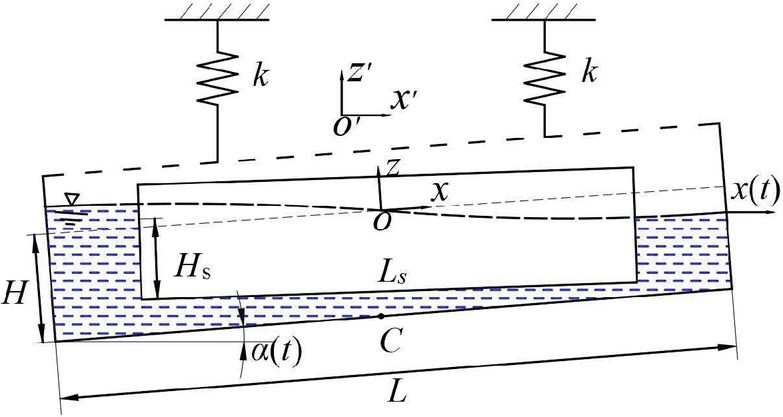
Figure 1 Location of the ship chamber, ship and water under the coupled longitudinal and pitch motions.
According to the design code for shiplift and reference [4, 5, 13, 27], the influence of ship can be reasonably simplified in the engineering hydrodynamic calculation. When the ship chamber is subjected to pure pitch motion, it rotates counterclockwise around the y-axis in the xoz plane. The absolute velocity potential can be expressed as the reference [27].
| (1) |
| (2a) | ||
| (2b) |
| (3) |
here the velocity potential represents the rigid body motion of the fluid. The velocity potential represents the liquid motion relative to the container. is the Stokes-Joukowski potential associated with the pitch motion of the ship chamber. . are the infinite set of generalized coordinates of the natural sloshing modes under pure pitch motion, which could be written as:
| (4) |
where indicates the natural sloshing frequencies. Once have been found, can be calculated using the Equations (1), (2) and (3).
When the ship chamber is subjected to pure longitudinal motion, the sloshing can be described same as Faltinsen and Timokha [24]:
| (5a) | |
| (5b) | |
| (5c) | |
| (5d) | |
| (5e) | |
| (5f) |
here indicates the velocity potential under longitudinal motion, denotes the free surface elevation under longitudinal motion. The exact procedures and solutions of Equations (5) are listed in Faltinsen and Timokha [24]:
| (6) | |
| (7) |
where are the modal functions under pure longitudinal motion. Analogue to the linear superposition principle [28] used in Faltinsen and Timokha [24] to analyze 6DOF space motions, the under coupled longitudinal and pitch motions can be expressed by linear superposition of and :
| (8) |
Then the absolute velocity potential under coupled longitudinal and pitch motions could be given by:
| (9) |
Based on the , the total pressure in the liquid can be expressed as:
| (10) |
here is the pressure in the air, is the water density, is the hydrostatic pressure. The last term is the hydrodynamic pressure, which can be rewritten as:
| (11) |
The total longitudinal hydrodynamic force acting on the ship chamber walls, per unit width, is obtained from integration the hydrodynamic pressure over the wet areas, such that:
| (12) |
While the hydrodynamic moment about the point C, per unit width, can be determined by:
| (13) |
By properly integrating the pressure over the wet areas, the above moment and force can be expressed as:
| (14) | ||
| (15) | ||
| (16) |
where denotes the hydrodynamic moment with respect to point coming from the pressure on the bottom, denotes the hydrodynamic moment for point resulting from the pressure on the wall.
2.2 Engineering Simplified Formulas
As shown in Table 1, the filling depth ratio for most of shiplifts currently being used in China are entirely less than 0.05. Base on the special situation, Equations (14), (15) and (16) would be further simplified for structural dynamics analysis and earthquake resistant design of the shiplift system.
Table 1 Ratio of depth to length in different shiplifts
| Shiplift Names | Current Status | Ratio of Depth to Length |
| Three Gorges shiplift | In use | 0.0292 |
| GouPitan shiplift/PengShui shiplift | In use | 0.0424 |
| GaoBazhou shiplift/GeHeyan shiplift | In use | 0.0405 |
| YanTan shiplift | In use | 0.0468 |
| TingZikou shiplift | In use | 0.0216 |
| ShuiKou shiplift | In use | 0.0219 |
Table 2 Convergence of , , and at different filling depth ratios under the condition of , ,
| 0.02 | 12.23 | 13.67 | 10.5% | 57.02 | 57.72 | 1.21% | 15.38 | 17.25 | 10.8% |
| 0.03 | 19.00 | 21.18 | 10.3% | 67.48 | 67.47 | 0.02% | 33.53 | 38.49 | 12.9% |
| 0.04 | 3.637 | 3.632 | 0.1% | 3.410 | 3.401 | 0.26% | 3.104 | 3.105 | 0.03% |
| 0.05 | 4.365 | 4.288 | 1.8% | 3.101 | 3.093 | 0.26% | 3.712 | 3.711 | 0.03% |
As shown in Table 2, for the , has excellent convergence, only taking the lowest mode () can control the error within 1.5%. and will generate an error of less than 11% and 13%, respectively. Moreover, it is evident that occupies less than 0.5% of the . That is, can be reasonably ignored in engineering design. It will be further validated in the following case simulations.
Through the above analysis, Equations (2.1), (14) and (15) can be further simplified by only retaining the lowest mode:
| (17) | ||
| (18) | ||
| (19) |
here is the longitudinal hydrodynamic force, is the total hydrodynamic moment, is the lowest modal function and is the lowest natural frequency of the contained fluid. Equations (17) to (19) are more applicable to the calculation of hydrodynamic pressure and force when the ship chamber encounters longitudinal and pitch coupling motion under non-seismic conditions. And the liquid filling ratio of the ship chamber must be less than 0.05 ().
3 Results and Discussion
To validate and analyze the reliability of the above formulas, two main test cases have been conducted. For both cases, a two-dimensional ship chamber (part of the Three Gorges shiplift) is used. The filling depth ratio is 0.03, with m and m. The first case is to compare the free surface elevation under coupled motions. While the second one is to compare the longitudinal force and hydrodynamic moment under earthquake and non-earthquake conditions.
3.1 Validation
Sloshing caused by the coupled motions would be validated by comparing the free surface elevation. Based on the linear shallow water theory [16], under coupled motions can be derived as:
| (20) |
where is the free surface elevation obtained by linear shallow water theory, indicates the longitudinal motion, represents the pitch motion.
While the the free surface elevation under coupled longitudinal and pitch motions derived by linear modal theory could be given by:
| (21) |
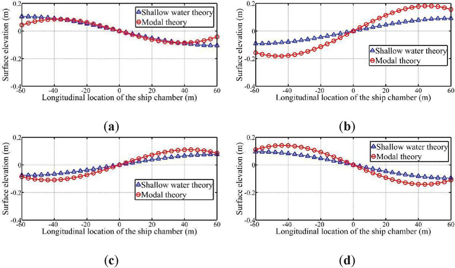
Figure 2 Comparison of the free surface elevation between (triangle symbol) and (round symbol) at (a), (b), (c) and (d) under coupled motions, , , .
According to the constraints of the actual engineering conditions of the Three Gorges shiplift, m, rad and are set. The (triangle symbol) and (round symbol) are then observed in Figure 2.
and are compared at four different times ( s, 45 s, 60 s, 80 s), which are any four times in a cycle. It is obvious that derived by linear modal theory provides a good match with the linear shallow water theory. The maximum difference at the ship chamber walls ( m) is 0.0659 m ( s), which is much smaller than the water depth, m. The occurrence of such a phenomenon well explained that it is suitable to apply the linear modal theory to simulate the shallow water sloshing in the ship chamber under coupled motions.
3.2 Hydrodynamic Moment
A further comparison between the Housner model (currently widely used in the shiplift seismic design) and the Equations (17) to (19) is shown in Tables 3 and 4.
Table 3 Hydrodynamic moment under different working conditions, , ,
| Earthquake Intensity | ||||
| 7 | ||||
| 8 | ||||
| 9 | ||||
| Non-earthquake |
Table 4 Longitudinal force under different working conditions, , ,
| Earthquake Intensity | ||||
| Non-earthquake |
As shown in Table 3, , and are the hydrodynamic moments under coupled motions, pure longitudinal motion and pure pitch motion, respectively. While is the hydrodynamic moment directly calculated by the Housner model. only has a small growth with 2x increase in peak acceleration under earthquake condition. More than this, there is little difference for under seismic or non-seismic condition. Such behavior is rather unreasonable in comparison to , which has an obvious grow up with the rise of earthquake intensity. In addition, under non-seismic condition is much smaller than seismic condition. Incidentally, this confirms the correctness of Equation (18).
Since is composed by two parts ( and ), it allows to investigate the respective degree of contribution. For the earthquake resistant design, could be neglected (the largest proportion is less than 3%) to further simplify Equation (18). However, should be reserved (accounting for up to 27.32%) under the non-earthquake condition. This meaning that while the ship chamber is subjected to longitudinal seismic, Equations (18) and (19) can be further simplified as:
| (22) | |
| (23) |
Analysis results display that the Equations (22) and (23) are more applicable to the calculation of hydrodynamic pressure when the ship chamber encounters longitudinal earthquake. Meanwhile, the liquid filling ratio of the ship chamber must be less than 0.05 ().

Figure 3 The hydrodynamic moment change with time under the condition of non earthquake (a) and earthquake with magnitude 7 (b) in Table 3.
It can be seen from the Figure 3 that whether seismic or non seismic conditions, the hydrodynamic moment changes periodically and does not diverge. This is because the influence of water sloshing damping is not considered in the calculation process. Figure 3 shows that the hydrodynamic moment tends to converge under both seismic and non seismic conditions, that is, the motion of the ship chamber tends to converge.
3.3 Hydrodynamic Force
The longitudinal force resulting from the sloshing plays a crucial role in the design of longitudinal guiding mechanism. Table 4 displays the variation of longitudinal force under different conditions. , and are the forces under coupled motions, pure longitudinal motion and pure pitch motion, respectively. stands for the hydrodynamic force calculated by the Housner model.
Similarly to the previous case, both and are the forces under pure longitudinal motion. It is worth noting that is far less than derived by Equation (17). Meanwhile, has an obvious growth with 2x increase in peak acceleration under earthquake condition. The difference between the seismic and non-seismic condition is more evident. That is, is more suitable to calculate the hydrodynamic force in the ship chamber. Apart from this, Table 4 also points out that accounts for less than 3% of under earthquake condition. Nevertheless, the proportion reaches 27.34% in non-seismic condition. This means that Equation (17) is in agreement with the non-seismic condition. But for seismic condition, Equation (17) can be further simplified as:
| (24) |
The analysis results show that the Equation (24) is more suitable for the calculation of hydrodynamic force when the ship chamber encounters longitudinal earthquake. The liquid filling ratio of the ship chamber must be less than 0.05 () simultaneously.
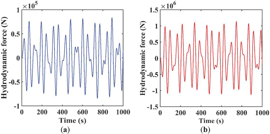
Figure 4 The hydrodynamic force change with time under the condition of non earthquake (a) and earthquake with magnitude 7 (b) in Table 4.
It can be seen from the Figure 4 that the hydrodynamic force shows periodic oscillation changes in 0 to 1000 seconds. If the damping of water sloshing is taken into account, the peak value of the curve will eventually gradually attenuate and tend to converge. That is to say, the motion of the ship chamber will eventually show convergence.
4 Conclusions
An analytical methodology founded on the linear modal theory is newly presented to investigate the shallow water sloshing in the ship chamber under coupled longitudinal and pitch motions resulted by longitudinal earthquake. Engineering simplified formulations of the hydrodynamic moment and force are derived by using the linear superposition principle. The applicability of the proposed method is demonstrated against comparing with the linear shallow water theory of Verhagen and Wijngaarden [16]. Case simulations under seismic and non-seismic conditions illustrate the accuracy of proposed formulas with respect to the Housner model. The key observations are summarized as follows.
(1) For the ship chamber, a modal system describing the shallow water sloshing is developed. Within the allowable range of shiplift engineering precision, the infinite set of modal functions (, 3, 5…) could be accurately reduced with only retaining the lowest mode . The maximum error of hydrodynamic moment and force between and are lower than 1.3% and 10.5%, respectively. The convergence error comparing with the currently widely used Housner model (hydrodynamic moment 1.5% and hydrodynamic force 55%) is greatly improved.
(2) For the rectangular ship chamber with filling depth ratio less than 0.05, the hydrodynamic moment resulting from pressure on the walls can be reasonably ignored regardless of earthquake, which accounts for less than 0.5% percent of total hydrodynamic moment.
(3) The newly proposed engineering formulas of hydrodynamic moment and force can be used to simulate the shallow water sloshing in ship chamber and rectangular liquid storage container with similar filling ratio. In addition, it can effectively supplement the missing part of longitudinal seismic calculation part in the current design code for shiplift.
Funding Statement
This study was supported by the Hubei University of Science and Technology PhD Start-up Fund Project [No. BK202112] and National Key R&D Program of China [No. 2016YFC0402002], and the authors gratefully acknowledge this support.
Data Availability
The data used to support the findings of this study are included within the article.
Conflicts of Interest
The authors declare that there is no conflict of interest regarding the publication of this paper.
References
[1] Housner, G. W. Earthquake pressures on fluid containers. Report EERL-1954-3, Earthquake Engineering Research Laboratory, California Institute of Technology, Pasadena, 1954.
[2] Housner, G. W. Dynamic pressures on accelerated fluid containers. B. Seismol. Soc. Am. 47(1) (1957) 15–35.
[3] Housner, G. W. The dynamic behavior of water tanks. B. Seismol. Soc. Am. 53(2) (1963) 381–387.
[4] Cheng, X., Shi, D., Li, H., Xia, R., Zhang, Y., Zhou, J. Stability and parameters influence study of fully balanced hoist vertical ship lift. Struct. Eng. Mech. 66(5) (2018) 583–594. doi: 10.12989/sem.2018.66.5.583.
[5] Zhang, Y., Shi, D., Shi, L., Xia, R., Cheng, X., Zhou, J. Analytical solution of capsizing moments in ship chamber under pitching excitation. P. I. Mech. Eng. C-J. Mec, 2019. https://doi.org/10.1177/0954406219843327.
[6] Chen, B. F. Viscous fluid in tank under coupled surge, heave, and pitch motions. J. Waterw. Port. Coast. 131(5) (2005) 239–256. DOI: 10.1061/(ASCE)0733-950X(2005)131:5(239).
[7] Stephen, J. J., Sannasiraj, S. A., Sundar, V. Numerical simulation of sloshing in a rectangular tank under combined horizontal, vertical and rotational oscillations. P. I. Mech. Eng. M-J. Eng. 230(1) (2016) 95–113. DOI: 10.1177/1475090214533512.
[8] Graham, E. W., Rodriguez, A. M. Characteristics of fuel motion which affect airplane dynamics. J. Appl. Mech-T. ASME. 19 (1952) 381–388.
[9] Eide, D. G. Preliminary analysis of variation of pitch motion of a vehicle in a space environment due to fuel sloshing in a rectangular tank, NASA TN-D-2336, 1964.
[10] Abramson, H. N. The dynamic behavior of liquids in moving containers. NASA Special Publication 106(7) (1966).
[11] Dodge FT. The new dynamic behavior of liquids in moving containers. [Update of NASA SP-106]. San Antonio, Texas: Southwest Research Institute, 2000.
[12] Ibrahim, R. A. Liquid Sloshing Dynamics: Theory and Applications. Cambridge University Press, Cambridge, 2005. DOI: 10.1017/CBO9780511536656.015.
[13] Liao, L.K. Safety analysis and design of full balanced hoist vertical shiplifts. Struct. Eng. Mech. 49(3) (2014) 517–522. DOI: 10.12989/sem.2014.49.3.311.
[14] Li, Y., Di, Q., Gong, Y. Equivalent mechanical models of sloshing fluid in arbitrary section aqueducts. Earthquake. Eng. Struct. Dyn. 41(6) (2012) 1069–1087. DOI: 10.1002/eqe.1173.
[15] Li, Y., Wang, J. A supplementary, exact solution of an equivalent mechanical model for a sloshing fluid in a rectangular tank. J. Fluid. Struct. 31(5) (2012) 147–151. DOI: 10.1016/j.jfluidstructs.2012.02.012.
[16] Verhagen, J. H. G., Wijngaarden, L. V. Non-linear oscillations of fluid in a container. J. Fluid. Mech. 22(4) (1965) 737–751. DOI: 10.1017/S0022112065001118.
[17] Antuono, M., Bouscasse, B., Colagrossi, A., Lugni, C. Two-dimensional modal method for shallow-water sloshing in rectangular basins. J. Fluid. Mech. 700(6) (2012) 419–440. DOI: 10.1017/jfm.2012.140.
[18] Antuono, M., Brocchini, M. Beyond boussinesq-type equations: semi-integrated models for coastal dynamics. Phys. Fluids. 25(1) (2013) 815–827. DOI: 10.1063/1.4774343.
[19] Antuono, M., Bardazzi, A., Lugni, C., Brocchini, M. A shallow-water sloshing model for wave breaking in rectangular tanks. J. Fluid. Mech. 746(3) (2014) 437–465. DOI: 10.1017/jfm.2014.127.
[20] Antuono, M., Lugni, C. Global force and moment in rectangular tanks through a modal method for wave sloshing. J. Fluid. Struct. 77 (2018) 1–18. DOI: 10.1016/j.jfluidstructs.2017.11.004.
[21] Faltinsen, O.M., Rognebakke, O.F., Lukovsky, I.A., and Timokha, A.N. Multidimensional modal analysis of nonlinear sloshing in a rectangular tank with finite water depth. J. Fluid. Mech. 407 (2000) 201–234. DOI: 10.1017/S0022112099007569.
[22] Faltinsen, O.M., and Timokha, A.N. An adaptive multimodal approach to nonlinear sloshing in a rectangular tank. J. Fluid. Mech. 432 (2001) 167–200. DOI: 10.1088/1468-5248/2/1/007.
[23] Faltinsen, O.M., and Timokha, A.N. Asymptotic modal approximation of nonlinear resonant sloshing in a rectangular tank with small fluid depth. J. Fluid. Mech. 470 (2002) 319–357. DOI: 10.1017/S0022112002002112.
[24] Faltinsen, O.M., and Timokha, A.N. Sloshing. Cambridge University Press, 2009.
[25] Strand, I. M., Faltinsen, O.M. Linear sloshing in a 2D rectangular tank with a flexible sidewall. J. Fluid. Struct. 73 (2017) 70–81. https://doi.org/10.1016/j.jfluidstructs.2017.06.005.
[26] Kolaei, A., Rakheja, S., Richard, M. J. Coupled multimodal fluid-vehicle model for analysis of anti-slosh effectiveness of longitudinal baffles in a partially-filled tank vehicle. J. Fluid. Struct. 70 (2017) 519–536. DOI: 10.1016/j.jfluidstructs.2017.02.012.
[27] Zhang Y, Shi D, Liao L, et al. Pitch stability analysis of high-lift wire rope hoist vertical shiplift under shallow water sloshing-structure interaction. Proceedings of the Institution of Mechanical Engineers. Part K, Journal of Multi-body Dynamics. 233(4) (2019) 942–955. DOI: 10.1177/1464419319850666.
[28] Haberman, Richard. Applied partial differential equations: with Fourier series and boundary value problems: International Edition. Pearson Schweiz Ag, 2012.
Biographies

Jianbao Yang, a lecturer at Hubei University of Science and Technology, he earned a Master’s degree from Shihezi University, Xinjiang, China, in 2017. His current research interests include fluid mechanics, medical engineering, neural network.

Yang Zhang, a lecturer at Hubei University of Science and Technology, he earned a Doctor of Engineering from Wuhan University, Wuhan, China, in 2020. His current research interests include shiplift, fluid mechanics, fluid-structure coupling, multi-body dynamics.

Duanwei Shi, professor and doctoral advisor of Wuhan University. Research direction: mechanical system dynamics, virtual prototyping technology, CAE. The research on the dynamic performance of the main structures of the three gorges shiplift, Xiangjiaba shiplift, Danjiangkou shiplift, Pengshui shiplift and Gaobazhou shiplift has been completed.
International Journal of Fluid Power, Vol. 24_3, 607–624.
doi: 10.13052/ijfp1439-9776.2439
© 2023 River Publishers