Classification and Review of Variable Displacement Fluid Power Pumps and Motors
Samuel Kärnell* and Liselott Ericson
The Division of Fluid and Mechatronic Systems, The Department of Management and Engineering, Linköping University, Sweden
E-mail: samuel.karnell@liu.se; liselott.ericson@liu.se
*Corresponding Author
Received 07 May 2022; Accepted 03 October 2022; Publication 29 April 2023
Abstract
Displacement control of positive displacement machines has been a part of fluid power since the early days. Some of the early hydraulic presses already used two different displacement settings, though this was realised by using two different pumps rather than changing the displacement. Later, radial motors with variable stroke length appeared, followed by other designs of variable machines, such as swashplate machines, bent-axis machines, and variable vane machines. All these solutions control the displacement by varying the volume difference of the displacement element – but there are other ways of achieving this. Most have not passed the research state, but some are commercially available. In this paper, different ways of varying the displacement are presented and classified. The classification divides concepts into either control of displaced fluid or control of usage of displaced fluid. In turn, these concepts can be either on system level or displacement element level. This results in four main classes, which to some extent can describe the characteristics of the control.
Keywords: Variable displacement, hydraulic pumps, positive displacement machines, review.
1 Introduction
Hydraulic machines are often classified as either roto-dynamic or positive displacement machines. Roto-dynamic machines are usually used in low-pressure applications (up to a few MPa), such as fluid transportation. However, this paper deals with rotary positive displacement machines, which generally are used in fluid power applications where higher pressure is desired.
An ideal positive displacement machine provides constant flow independent on the pressure level. Positive displacement machines are found in almost all fluid power applications. The term “machine” can refer to both a pump and a motor. A pump transforms mechanical energy into hydraulic energy, and a motor works the other way around. Many positive displacement machines can perform both tasks, but they are usually optimised for one or the other. In pump applications, the ability to control the flow rate or the outlet pressure level is usually desired. This can be done by varying the rotational speed of the pump or by varying the amount of flow that is delivered by the pump for each revolution, i.e. the displacement. With regard to motors, the displacement can instead be used to control the torque or speed on the output shaft. There are many possibilities when it comes to varying the displacement in rotational machines. In this paper, the different ways of varying the displacement are classified and reviewed.
1.1 Historical Overview
The oldest known positive displacement machine is the Archimedean screw, which basically is a single screw contained in a cylinder. Its invention is sometimes attributed to Archimedes, but Archimedes did not invent it, he described its function. In fact, the Archimedean screw appears to date back to Ancient Egypt where it was used for water conveyance [79]. It took until around 200 BCE before the first piston pump appeared and its invention is credited the Greek inventor and mathematician Ctesibius. The pump in question was a so-called reciprocating force pump, which likely was used for firefighting [77]. It was based on pistons sliding in cylinders and it used check valves for commutation. The pump was powered by a lever, but it did not take long until similar pumps with rotational inputs were fabricated. An example can be found in Heron’s wind-powered organ [61].
The years passed on and pump development continued. But quite slowly. In the year 1588, Agostino Ramelli released a book describing different machines that could be used for welling applications, for example [64]. The book is often stated to be the first engineering handbook and it contains illustrations and descriptions of various screw pump configurations, different piston pump arrangements, and the first known records of vane pumps. This indicates some development in the hydraulic field since Ctesibius’ time, but applications were still limited to water conveyance. Around the year 1600, Johannes Kepler came up with what appears to be the first gear pump. He built a working model, but it did not revolutionise society [77]. Kepler moved on with astronomy related work, but others continued to develop hydraulic machines and theories related to fluid power. One of them was Blaise Pascal, who in the mid-17th century formulated the hydrostatic law, which attested to the possibilities of force amplification provided by hydrostatics. Around the same time, the first experiments with steam pumps were conducted, and in the beginning of the 18th century, Thomas Newcomen developed the first commercial steam engine, which James Watt later improved. Although, the steam engines were mainly used to pump water from mines, the pumping mechanism itself was still a force pump.
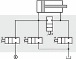
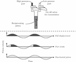
It was not until the late 18th century that someone started to use pumps for applications other than conveying fluids. That someone was Joseph Bramah. In 1795, he patented the hydraulic press [12] and this invention is often considered the starting point of hydrostatic engineering. He was the first to make practical use of Pascal’s ideas of force amplification. Already in the beginning, the presses were working at a few hundred bars, and it did not take long until some machines were equipped with two pumps: one with large displacement for high velocities and low pressures, and one with small displacement for low velocities and high pressures [77]. This can be regarded as a type of displacement control. Bramah truly saw the potential of fluid power. Already in the patent from 1795, he mentioned the possibility of using hydrostatics for power transmission, and in 1812, he registered a patent in which he mentioned hydraulic power networks for cities [13]. He died a few years later, but in the second half of the 19th century, his ideas of hydraulic power networks became a reality in several cities, mainly in the United Kingdom. They were used to power everything from workshop machinery and cranes to theatre stages. When the first networks were built, they were powered by steam engines or water turbines (which were later replaced by electric motors) and they used so-called three-throw ram pumps (a kind of piston pump with three aligned pistons) [23, 24]. The hydraulic fluid was water, and the pressure levels were generally in the range of 5 to 7 MPa. In the 19th century, the development of hydraulic machinery was booming, especially in Great Britain. Cylinders and motors were used to perform work tasks by converting hydraulic energy to mechanical energy in all sorts of applications. And on the consumer side of the transmission, things started to happen regarding power control. For example, William George Armstrong came up with a cylinder/valve arrangement in which two different effective cylinder areas could be used, thereby achieving both high and low speeds efficiently [72]. The arrangement is shown in Figure 1.
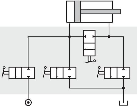
Figure 1 Schematics for Armstrong’s “double power” valve/cylinder arrangement.
Armstrong also invented different hydraulic fixed displacement rotary motor designs. However, around the 1880s other people developed variable motors based on radial piston designs, such as John Hastie and Arthur Rigg [34, 72]. An illustration of the Hasties motor is shown in Figure 2. These machines are the first continuously variable displacement machines that the authors of this paper have identified, and already back then the displacement could be automatically controlled via mechanical feedback systems.
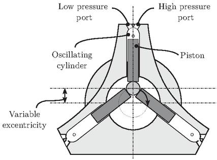
Figure 2 Principal illustration of a variable Hastie motor.
Towards the end of the 19th century, fluid power development also started to take off in the United States. In 1893, an axial piston pump with variable swashplate angle was patented by Cooper and Hampton [17]. Note that different types of fixed axial piston pumps already were included in Ramelli’s book from 1588 [64], but during the time when reciprocating steam engines were used as prime movers, swashplate pumps did not become very popular. However, prime movers with rotational output started to become more common towards the end of the 19th century, and in Cooper and Hampton´s patent it was emphasised that the pump is suitable for electric prime movers. Still, there was no immediate success, but the development of swashplate machines continued. In the beginning of the 20th century, Janney and Williams patented several solutions related to such machines. An example is a patent from 1906 for a variable speed transmission [41]. This was based on two axial piston machines and oil was suggested as fluid. Oil had already been used in e.g. seed presses since the 1820s [77] and the beneficial lubrication and corrosion properties were known, but most machines were still using water as the working fluid at this time. However, in the first half of the 20th century, the electric grid outcompeted most hydraulic networks. The consequence was a stronger focus on development of self-contained hydraulic systems, where military applications had a prime role in the development. This in combination with the availability of mineral oil led to a movement towards oil-based fluid power systems.
1.2 Current Trends
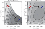
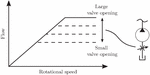
There has naturally been considerable development in hydraulic components and systems since the beginning of the 20th century, but in principle, they are similar to the ones we find today. However, in the mobile hydraulic sector, we are currently undergoing a transition where internal combustion engines are being replaced by electric motors. This means that speed control of pumps is more relevant than before. However, displacement control can still be of interest since it can offer downsizing possibilities (i.e. by reducing torque requirements on the motor) as well as improved efficiency [94] and dynamic performance [95]. The possibility to improve the efficiency is illustrated in Figure 3, where it is shown how the operating point can be moved for a specific pressure and flow. The figure also shows that the torque requirement is reduced. Another thing offered by electrification is the possibility of utilising electric energy recovery. This requires that the same hydraulic machine functions as both a pump and motor. This is important to bear in mind when different displacement controls are compared.
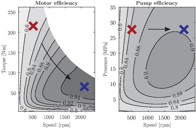
Figure 3 Example of how the efficiency can be improved by moving the operating points using variable displacement. The two operating points correspond to the same pressure and flow rate. Effects of reduced efficiency at part displacement are not included. The efficiency maps are based on data for a permanent synchronous magnet motor and a bent-axis pump.
Electrification also means increased focus on energy efficiency, and one path towards more efficient systems is to use so-called common pressure rails. In such systems, displacement-controlled motors are highly relevant for rotary motions, and they should ideally be able to work in pump mode as well to allow energy recovery. Linear motions are more problematic, but there are several possible solutions. One is to opt for digital hydraulics, where multi-chamber cylinders and/or multiple pressure rails are used [21]. Another is to use hydraulic transformers (sometimes called converters), which can be based on displacement-controlled rotary machines (see e.g. [3]) or on fast switching valves in combination with inertial effects, inspired by electric converters [76]. The latter types are not part of the scope in this paper.
Electrification is also apparent in the control. Electronic control is becoming more common in hydraulic systems in general. Electronically controlled valves are increasingly being used, and system states are being measured to a greater extent. Displacement control is no exception, and it is not controversial to expect increasing demand for electronically controlled machines, compared to traditional hydro-mechanical controlled machines.
2 General Pump/Motor Design
Before the different types of displacement control are discussed, a brief summary of the working principles of a hydraulic machine are presented.
2.1 Operating Modes
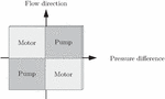
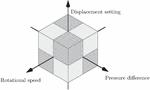
Hydraulic machines are frequently classified according to their design (e.g. axial piston, radial piston, vane), but a functional classification (i.e. what they can do) is sometimes more relevant. In principle, it is only the direction of flow and the pressure difference that matter. From a functional perspective, a hydraulic machine has four operating modes: two pump modes and two motor modes. It is therefore common to divide the modes of operation into quadrants, as in Figure 4.
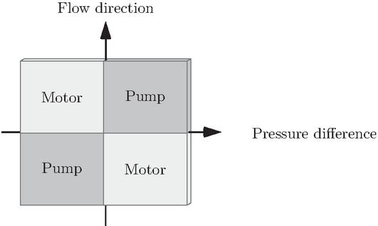
Figure 4 Operating modes in quadrant division.
The flow direction can usually be varied by either changing the sign of the displacement setting (this is usually referred to as over-centre control) or the rotational speed. Therefore, there are in fact eight different operating modes. These are graphically represented in Figure 5. However, if both the sign of the displacement and speed is changed, the changes will cancel each other out and the flow direction will not change. Therefore, a quadrant representation with either displacement setting or rotational speed as a replacement for the flow direction is usually sufficient. Traditionally, the displacement setting has been used to define the flow direction. This does typically apply to mobile applications since it has not been of high relevance to change rotational speed direction in machines powered by combustion engines, but it also applies to the industrial sector. However, the increased use of modern frequency converters for control of electric machines changes these conditions, both for mobile and industrial applications.
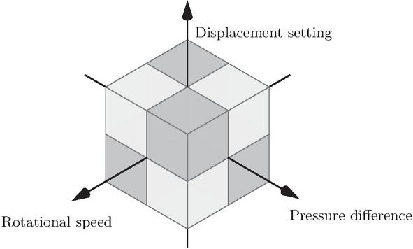
Figure 5 Operating modes in octant division.
2.2 Working Principle
Positive displacement machines can typically be considered as being built up from several separated displacement elements. In piston machines, each cylinder corresponds to a displacement element. In vane machines, the displacement elements are the volumes between the different vanes, while in gear machines, the volume between the tip of each gear tooth corresponds to the displacement element. In the piston pump example, the cylinders are connected to the low-pressure inlet when the cylinder volume increases and to the high-pressure outlet when it decreases. This switching between inlet and outlet is referred to as commutation. The type of commutation has a great impact on both the performance and the displacement control possibilities.
2.3 Commutation Techniques
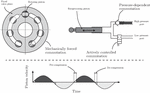
Commutation relates to the separation between the inlet and outlet ports. To achieve operation that is as smooth and quiet as possible, the pressure in the displacement element should match the inlet or outlet pressure during commutation. There are principally three types of commutation techniques that can be found. These are:
• Mechanically forced
• Pressure-dependent
• Actively controlled
Examples of these commutation techniques are shown in Figure 6. Mechanically forced commutation means that the timing is defined by fixed mechanical connections. The openings to the inlet and outlet can then depend on the rotational angle, for example. An example of this is the valve plate (sometimes called the port plate) in e.g. swashplate machines. This technique is generally applied when the displacement elements (e.g. pistons or vanes) are rotating with the shaft. A problem with this technique is matching the pressure in the cylinder with the system pressure during opening. So-called pressure-relief grooves are often used to achieve smooth commutation for a large operating range.
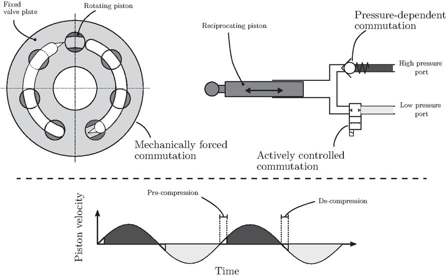
Figure 6 Examples of different commutation techniques. The bottom part of the figure shows how the commutation can work. The opening to the different pressure ports are colour coded.
Figure 6 also shows an example of pressure-dependent commutation for one port, where a check valve determines the commutation timing. This means that a nearly optimal pressure matching is always achieved since the pressure in the cylinder will match the outlet pressure when the valve opens. However, the dynamics of the check valves can make the commutation method less ideal for high speeds. Also note that a pump with check valves cannot run as a motor and that the flow direction is independent of the shaft’s rotational direction. This commutation technique is primarily relevant for pumps where the displacement elements are not rotating with the drive shaft, which includes some radial piston pumps, axial piston pumps with rotating swashplates (sometimes called wobble plate pumps) and triplex pumps. The check valves can be replaced with actively controlled valves. The commutation is then actively controlled. This is also illustrated in Figure 6.
Note that the solutions shown in Figure 6 are just examples of possible implementations. Furthermore, different types of commutation are not always clearly distinguishable. For example, the actively controlled valve shown in Figure 6 can have a built-in check valve in its closed position. The pump could then work passively with pressure-dependent commutation, but since the possibility exists to actively control the commutation for the inlet, it can be considered as actively controlled. Another type of active control that also can work passively, but with mechanically forced commutation, can be achieved by having a rotatable valve plate [32, 25, 35]. Furthermore, combinations of mechanically forced and pressure-dependent commutation have also been investigated. An example is the valve plate with inbuilt check valves [32]. Such a design should be classified as pressure-dependent since the check valve is used for the commutation part of the stroke in the intended mode of operation. It should also be stated that one machine can have different types of commutation for different ports.
3 Classification of Displacement Control Methods
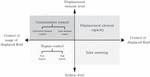
In this section, the known displacement control methods, which will be reviewed in detail in Section 4, are classified. The classification is illustrated in Figure 7. The control is either based on how much fluid is displaced or the usage of the displaced fluid. This can be controlled on both the displacement element level and system level.
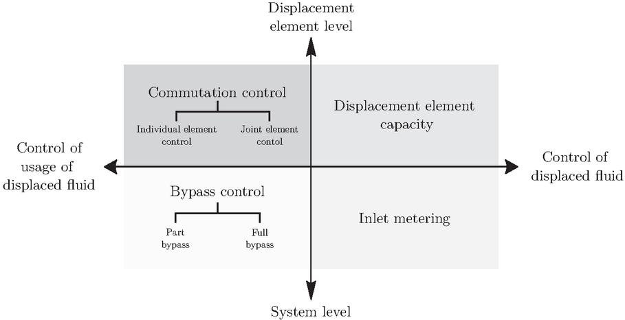
Figure 7 Classification of displacement control methods.
First, the control methods can be divided into either displacement element level or system level. At displacement element level, the displacement is controlled within the machine. At system level, the displacement is instead controlled by a valve arrangement that is placed upstream or downstream of the machine – the commutation or the geometry of the machine itself is not affected. This principally means that the hydraulic machine can be replaced by another machine type, but the displacement control can remain (even though it might have to be tuned).
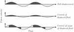
At displacement element level, the displacement can be varied by either changing the swept capacity of the displacement elements (i.e. control of displaced fluid) or by changing how much of the capacity is used by controlling the commutation (i.e. control of usage of displaced fluid). The traditional way is to change the capacity (e.g. to vary the stroke length in a piston machine), but there are also plenty of other ways to control the commutation. These are here categorised according to whether all displacement elements in the machine can be controlled individually or not. An comparative illustration of “control of displaced fluid” and “control of usage of displaced fluid” is shown in Figure 8.
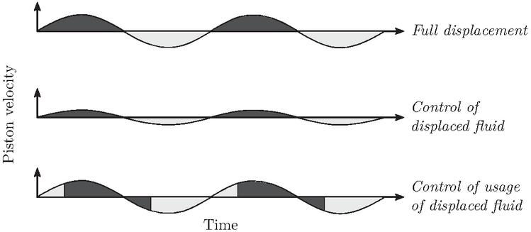
Figure 8 Exemplifying illustration of how the displacement can be varied by control of the capacity and the usage of the capacity. Pre- and de-compression is neglected.
At system level, the operation of the machine is unchanged, but a valve arrangement is added for the displacement control. The valves can be used to meter the inlet flow. By doing so, one can control to what degree the displacement elements are filled (i.e. control of displaced fluid). When the inlet flow is metered, the displacement elements are partially filled up due to cavitation of the fluid. One can also use the valve block to bypass flow that is not needed (i.e. control of usage of displaced fluid). Most machines have only one outlet. In that case, only full bypass is relevant. Fast switching valves can then be used to obtain a nearly continuous flow control. However, if the machine has multiple isolated outlets, part bypass can be applied. Then the outlets can be individually bypassed, and a discretely variable displacement can be obtained.
4 Review of Control Methods
In this section, methods that have been proposed in the literature are summarised and reviewed. They are grouped according to the classification presented in Figure 7.
4.1 Displacement Element Capacity
Most commercial variable machines are of this category. The common machines are described in Section 4.1.1. However, there are also some more novel approaches. These are described in Section 4.1.2.
4.1.1 Conventional control
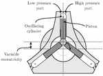
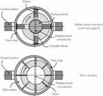
In essentially all commercial variable axial piston machines, the displacement is varied by means of the stroke length. In swashplate machines, the stroke length is controlled by the angle of the swashplate. An example of this is shown in Figure 9, together with a principal sketch of a variable bent-axis machine, which relies on similar principles. In both these machine types, the displacement element capacity is varied with the angle. In radial piston machines and vane machines, the displacement element capacity is instead varied with the eccentricity between the rotating shaft and a surrounding ring. Such machines are shown in Figure 10.
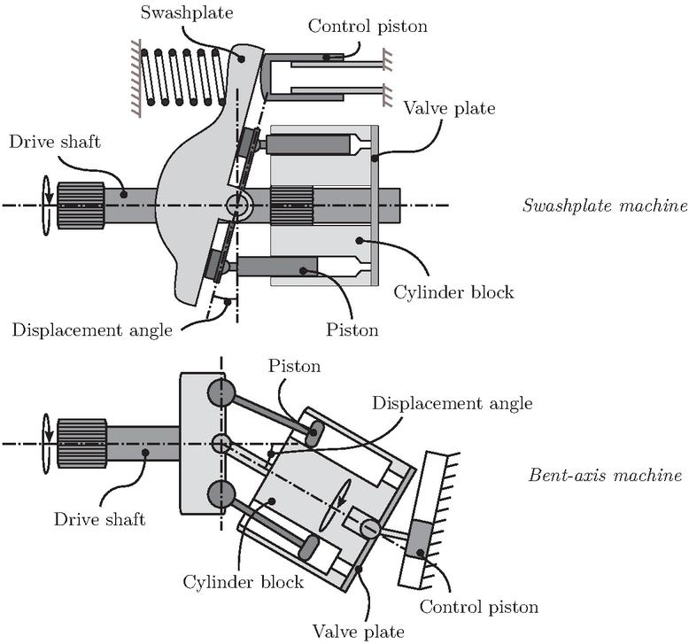
Figure 9 Examples of conventional variable machines where the displacement element volume difference can be varied by changing the angle.
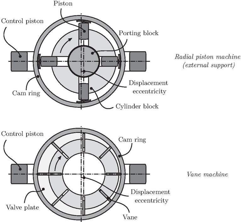
Figure 10 Examples of conventional variable machines where the displacement element volume difference can be varied by changing the eccentricity.
The possibility of varying the swashplate angle was already included in the patent by Cooper and Hampton from 1893 [17], and this is one of the most common principles for achieving variable displacement. The angle can usually be controlled in the range around 20 to 20. There are several ways to actuate the swashplate. In early blueprints, one can see arrangements where a screw mechanism is used to vary the swashplate angle [41], and today there are still examples where a screw is adjusted either manually or with electric motors. These are usually very slow compared to hydro-mechanically controlled alternatives, where the angle is controlled by one or more pistons. Today, the angle is typically hydro-mechanically controlled. The variation of the hydro-mechanical control mechanism is considerable, but oscillations present a common problem. A damping orifice is normally implemented to stabilise the control. However, this can cause significant losses [1, 51]. Furthermore, the control itself requires a specific pressure to work. In closed-circuit pumps, this pressure is usually provided by an additional charge pump. In open circuits, the outlet pressure is used for the actuation of the displacement control. An additional disadvantage with varying the displacement by means of the swashplate angle is that that the dead volume is varied as well. This is a cause of additional compression losses, and it can also cause problems with noise in machines with mechanically forced commutation. The hydro-mechanical controller also suffers from limited controllability and flexibility, and it is hard to reach bandwidths beyond 25 Hz [54]. It is usually mechanically tuned by means of springs and it reacts to pressure signals in the system. An electronically controlled displacement offers more flexibility. This is usually achieved with so-called electro-hydraulic controllers, where electronically controlled valves are used to control the pressure in the control piston/pistons. The actuation alternatives are similar for all machines shown in Figures 9 and 10.
4.1.2 Non-conventional control
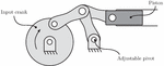
The aforementioned methods are common commercial options for varying the displacement. However, there are other ways to vary the displacement element capacity. As early as the first half of the 20th century, a variable stroke length was achieved by means of a stroke transformer [60], and more recently this principle has been researched at the University of Minnesota under the name adjustable linkage [91]. The principle is shown in Figure 11. The linkage can go from full to zero displacement with constant dead-volume. This design is claimed to be efficient at part displacement since the pump does not rely on hydro-dynamic bearings to the same extent as conventional pumps do. The losses should therefore scale better with the displacement setting. It can be noted, however, that the piston velocity does not follow a sinusoidal curve, and that the shape varies with the displacement setting.
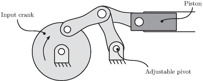
Figure 11 Adjustable linkage pump. The displacement is controlled by moving the adjustable pivot.
The adjustable linkage design was presented by Wilhelm and Van de Ven in 2011 [91]. In that paper, mechanical design parameters were analysed. In 2013, they presented a prototype [92]. Mechanical properties were analysed, and models were validated. It was stated that the volumetric footprint was about double that of fixed linkage. The same authors have also analysed the efficiency. Details can be found in [89, 93, 90]. Losses have been modelled and the models have been validated with experiments. The authors state that the pump is expected to have more than 90% efficiency for displacement settings above 10% for most operating conditions if low-friction bearings are used (losses due the commutation check valves excluded). However, the prototype did not have low-friction bearings and hence the measured efficiency was lower. It was also observed that the check valves used for commutation caused significant volumetric losses. The work on the adjustable linkage pump continued within the research group. In [30], Fulbright and Van de Ven presented an investigation of the dynamic response of the pump controller, and in [29] they incorporated the adjustable linkage in a radial piston motor. The motor design was further investigated by Larson et al. in [45], where a one-cylinder motor was experimentally evaluated on subsystem level.
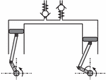
A different and innovative solution, in which the displacement element capacity can be varied, is the alternating flow pump, presented in by Foss and Li et al. [28, 46]. The alternating flow pump has pistons connected in pairs and the displacement setting is controlled by the phase angle between the pistons. Each piston pair is a displacement element since the cylinder volumes are interconnected. The working principle is illustrated in Figure 12. The phase angle is controlled by the pump case angle. The authors state that it should be possible to achieve over 90% efficiency for displacement settings greater than 10 %. A proof-of-concept prototype has been built and tested. However, the prototype did not achieve these levels due to large mechanical transmission losses, among other things.
Figure 12 Alternating flow principle with one piston pair. The displacement is controlled with the phase angle between the two pistons.
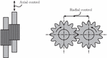
There have also been several attempts to make variable gear machines by allowing axial movements of the gears [7, 15, 96, 27]. A different approach that has been proposed is to change the distance between the gear axes (i.e. radial control) [71]. The basic ideas behind the different approaches are illustrated in Figure 13. The common problem with these solutions is internal leakage, and none of the solutions has yet had any commercial success.
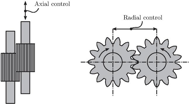
Figure 13 Different ways to control the volume difference in a gear machine. Note that sealing solutions are not considered in the figure.
4.2 Commutation Control
By controlling the timing of the commutation, the usage of the displaced flow can be controlled. Here, commutation control is divided into individual and joint element control.
4.2.1 Individual element control
When it comes to controlling the commutation, there are several proposed concepts. However, the most well-known is probably the so-called Digital Displacement® approach. Digital Displacement® is applicable to piston machines, and it makes use of one or more electronically controlled valves per piston. The usage of each piston stroke can thereby be controlled individually. This offers plenty of control possibilities. One possibility is to simply turn off cylinders by keeping them connected to the reservoir, but one can also control the usage of the stroke for each piston. A simple example of commutation in a Digital Displacement® machine is shown in Figure 14. The figure also shows examples of how a piston can be controlled.
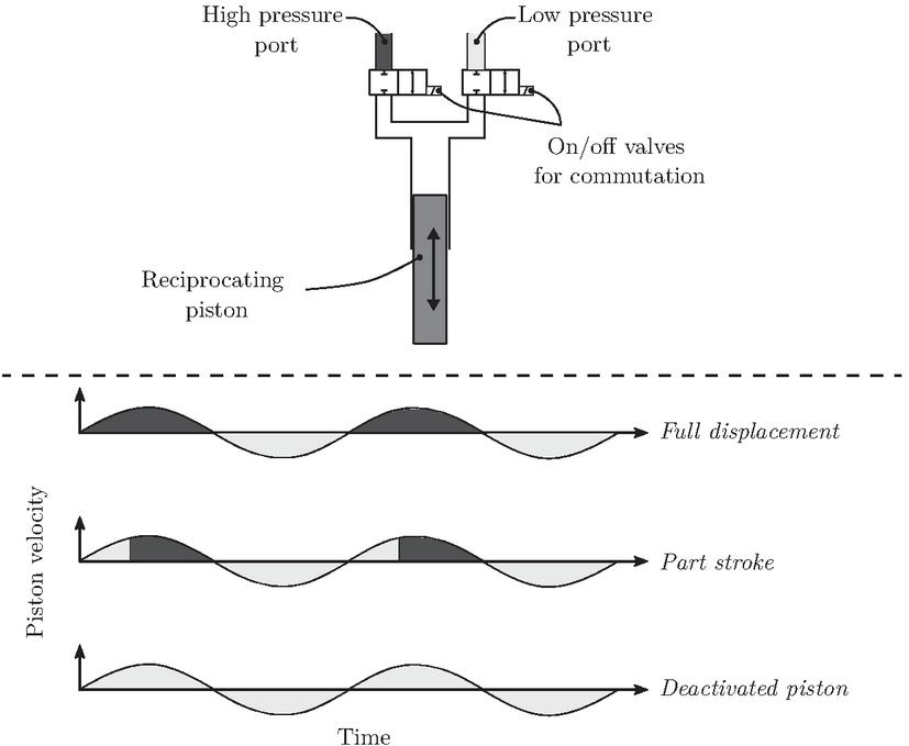
Figure 14 A type of Digital Displacement® machine. Note that check valves can be built in the on/off valves’ closed position to allow passive pumping. If the machine is supposed to only work in one pumping quadrant, one of the on/off valves can be replaced by a check valve. The bottom part of the figure shows some simplistic control examples, where the opening to the high and low pressure ports are colour coded.
The first patents for Digital Displacement® machines were filed towards the end of the 1980s by Salter and Rampen from the University of Edinburgh [75, 74]. In the first patent, they presented a solution for a pump, where an electronically controlled valve between the piston chamber and inlet was introduced. They describe how the piston can be turned off by having that valve open and they propose control methods (pressure and flow control) based on how many pistons should be activated per revolution. In the second patent, they added an electronically controlled valve between the piston chamber and the outlet port. This to allow motor operation. In 1992, Rampen presented his PhD thesis on the subject of Digital Displacement® [68]. The ideas from the patents above are elaborated in the thesis, but the focus is on pump operation. A prototype based on an axial piston pump with rotating swashplate (a wobble plate pump) was developed and analysed. It is, however, stated that more work on valve characteristics and noise is required. Since then, more work has indeed been carried out, and the company Danfoss are working on getting Digital Displacement® pumps out on the commercial market [18]. The pump is based on a radial piston design and claimed to offer fast response (zero to full displacement in half a revolution 8.5 ms), no control hysteresis, pressure-independent response, efficient part-load performance, and low idle losses. However, getting to where they are has taken considerable work, primarily by the company Artemis Intelligent Power, which was acquired by Danfoss. Throughout the years, Artemis Intelligent Power has developed numerous patents regarding control, valve design and system design (see e.g. [78, 67, 65, 16, 66]), and the company has looked into several applications including wind power transmissions, vehicle transmissions and off-highway hydraulics.
The principles of Digital Displacement® have also been investigated in academia. At Purdue University, there has been much work on different control strategies [40, 55, 14]. At Aalborg University, the focus has been on valve design for large Digital Displacement® machines for wind turbines [73, 58, 9], as well as on control [63] and tribological design aspects [42]. Some work has also been done at the University of Minnesota, where concepts with rotary valves have been proposed [82]. In addition, researchers at Tampere University have worked on Digital Displacement®. They have, amongst others, worked on Digital Displacement® transformers [37, 36, 48].
4.2.2 Joint element control
Prior to Digital Displacement®, similar solutions with mechanically controlled valves existed. A current example of such a pump can be found in the catalogue from Dynex Hydraulics [22]. The pump uses check valves for commutation, but additionally there is a valve between the inlet and the cylinder chamber that is mechanically opened by a cam. The phase of this opening can be varied to control the usage of the stroke length. All pistons have individual valves, but since the same cam controls all valves, the control is shared by all pistons. Another cam-based approach, which is more similar to the Digital Displacement® pump, has been presented by Helmus et al. [39].
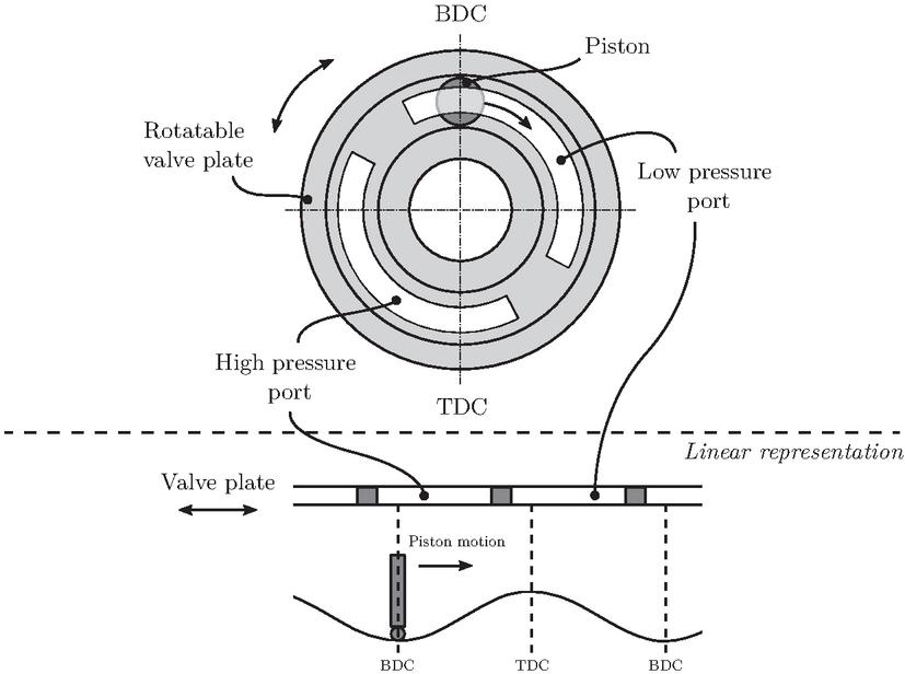
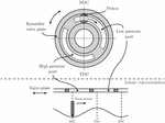
Figure 15 Working principle of a rotatable valve plate. The displacement is controlled with the angle of the valve plate. BDC refers to bottom dead centre and TDC to top dead centre. The bottom part of the figure shows a linear representation, where the rotation is translated into a linear motion.
The usage of the stroke can also be controlled by means of a rotatable valve plate, which makes it possible to move the commutation regions from the top and bottom dead centres to other regions of the stroke. Citroën filed a patent for that solution as early as the late 1950s [6]. The working principle is shown in Figure 15. The valve plate control is not only interesting from a displacement control perspective, but also in terms of pulsations. In [32], Grahl examined the potential to use valve plate control to reduce the noise by controlling the pre-compression angle. The principle of a rotating valve plate has also been incorporated in the hydraulic transformer by Innas [3, 2, 4]. An advantage with valve plate control is that the required control forces are small since the valve plate is pressure balanced to a high degree. But there are issues with cavitation and high pressure peaks during commutation at low displacement settings. This is because the commutation then occurs at high piston speeds. These issues have been highlighted by Ericson et al. [25]. The problems were, however, addressed by Heeger and Ericson in [35], where a double pump with two rotatable valve plates was used.
The aforementioned references are all for axial piston machines, but the concept is not limited to such machines. Equivalent solutions to valve plate control, but for a gerotor pump can also be found in the literature [52, 57].
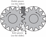
A type of commutation control has also been applied to external gear pumps. Devendran and Vacca have presented a variable external gear machine that was realised by means of a slider mechanism that could move the commutation point [19, 20]. The concept was able to control the displacement in the region from around 70% to 100 %. The working principle is illustrated in Figure 16 and can be considered as a refinement of Bowden’s patents from the late ’80s [10, 11]. In [87], Vacca and Devendran presented an analysis of different actuation systems for the slider (manual and pressure-compensated-based actuation). Problems with additional leakage due to the slider were also highlighted. In [80], Tankasala and Vacca considered the actuation forces on the slider. A solution to balance the forces, which reduces the required actuation forces and in turn allows for direct electronic control, was presented. The concept has also been adapted to low-pressure applications (3 MPa). This was presented by the same authors in [81].
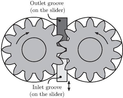
Figure 16 Slider mechanism in an external gear machine.
4.3 Inlet Metering
One possible way to turn off a displacement element in a Digital Displacement® machine is to keep both the inlet and outlet closed when the piston is retracting, and thereby cause cavitation. One can also make use of cavitation on system level. A restriction can be placed at the inlet of the pump. The flow that enters the pump can thereby be choked above a certain shaft speed. The characteristics are illustrated in Figure 17.
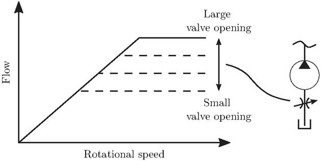
Figure 17 Ideal characteristics of a pump with inlet metering. The flow starts to be choked at the rotational speed where the plateau begins.
This technique is commercially applied in vehicle applications, both for fuel pumps and in fluid power circuits, such as servo steering [26]. In the latter example, the control is used as a flow rate limiter and not for flow control. In such applications, the pump is powered by the combustion engine, and the restriction is usually tuned so the plateau starts around the idle speed of the engine. The flow, and the required pump power, would then not increase with the engine speed.
A general problem with this type of flow limiting is the noise. Welschof examined the details of this in his PhD thesis from 1992 [88]. He compared it to phase angle control, a term used in electronics. Some years later, Fassbender presented his thesis on the same topic [26], where he, among others, focused on a pulsation dampener for the application. He also highlighted the possibilities of using the technique for flow control by actively controlling the restriction.
There has also been more recent research on the subject. In 2016, Wisch presented his PhD thesis, which focuses on the dynamics and efficiency of an inlet-metered pump [97]. The following year, Ali presented his PhD thesis [5] on efficiency and system implementation. Conclusions include that the efficiency is worse than for a conventional pump (which was not anticipated), but that the dynamic response is satisfactory. It was concluded that the pressure response of such a pump behaved like a first-order system. Overshoots in the control can thereby be avoided.
4.4 Bypass Control
Instead of choking the flow, it is possible to redirect the undesired flow, i.e. bypass the flow. This class can be divided into full bypass and part bypass. Part bypass is only applicable to machines with multiple isolated outlets.
4.4.1 Full bypass
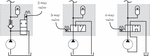
In electronics, pulse-width modulation (PWM) is a standard method used to control power. PWM entails fast switching between on and off. The ratio between the on-time and the total cycle time indicates the amount of maximum power being used. In electronics, transistors are used for the switching. In hydraulics, valves can be used instead. The use of fast-switching valves to obtain variable displacement has been investigated by several researchers. The PWM frequency has typically been in the range 10–100 Hz. It has been called software enabled variable displacement as well as virtually variable displacement. Here we will stick to the term virtually variable displacement. The general idea is that a fixed pump is used together with a fast-switching valve that either connects the pump outlet to the system or does not. An accumulator is used to reduce pulsations. Different possible implementations of the concept are illustrated in Figure 18. Note that the implementations with 3- and 4-way valves can also work as motors, but that the valves must be rearranged for motor operation when 2-way valves are used.
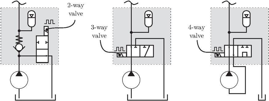
Figure 18 Different virtually variable displacement implementations. Fast-switching electronically controlled valves are used to divert the flow. Accumulators are used to reduce pulsations.
A 2-way-valve-based concept was presented and evaluated by Tomlinson and Burrows in 1992 [83]. Similar ideas were later presented by Li et al. [47] and experimentally evaluated by Rannow et al. [70]. It was shown to work as intended and that a high switching frequency could reduce the flow ripple and increase the bandwidth, but at the cost of reduced efficiency due to throttling during switching as well as compression losses in the volume between the pump and the valve. This negative impact could be reduced with a faster valve and a smaller volume. Some years later, a simulation model of a circuit based on the 3-way valve (but with a check valve incorporated as well) was developed and validated by Lumkes et al. [50]. The study drew similar conclusions to previous studies. The studies mentioned thus far only allowed the pump to work in one quadrant. However, a 4-quadrant solution was presented by Tu et al. in [85]. This was achieved by using a 4-way directional valve in combination with a proprietary 4-way rotary valve (corresponding 3-way valves have also been developed [84, 86]). The solution with the 4-way valve was claimed to reduce compression losses since the fluid being decompressed is directed to the inlet and not the tank, and also because it allows small compression volumes.
An advantage with switching hydraulics in general is that it is less vulnerable to contamination than traditional valve control [62]. However, a major problem with virtually variable displacement is the comparatively low efficiency, especially at high switching frequencies due to throttling during the switches. An obvious way to reduce the losses is to make the valves faster. But still, the switching time for the valves is counted in milliseconds, compared to the nanoseconds for transistors. Such switching times are not realistic for valves that require mechanical movement. Other complementary solutions may therefore be required to reduce throttling losses. One such solution is the so-called soft switching approach, which has been presented by Rannow and Li [69]. The solution relies on a check valve, a piston with a spring, and a lock mechanism. This introduces parallel flow paths and allows the flow to take other paths than through partially opened valves. According to the presented simulation study, the throttling losses during transition could be reduced by about 80 %. However, a soft switching solution was experimentally evaluated by Beckstrand et al. [8], but did not show any efficiency improvements.
4.4.2 Part bypass
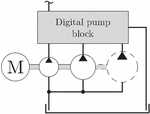
Double pumps, i.e. two pumps powered by the same shaft, have been around since the late 18th century. To avoid stalling the prime mover, one of the pumps has usually been equipped with a pressure controlled unloading valve (sometimes called a bypass valve). This setup can be considered an automatically controlled digital pump that offers two displacement settings. One can also consider having more pumps and thereby obtaining more discrete steps, and the unloading valves can be electronically controlled to allow a higher degree of flexibility. A general illustration is shown in Figure 19. An example of such a system was presented by Moorhead in 1984 [56]. He presented a so-called digital pumping system for an injection moulding machine. The system was based on several fixed pumps of different sizes and electronically controlled unloading valves. It was claimed to be considerably less costly but with slightly less efficiency than a variable pump solution. Still, there is not much literature focusing on digital pump systems.
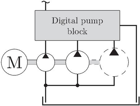
Figure 19 Digital pump. The number of pumps is arbitrary. Each pump is able to be unloaded individually.
The main problem with the digital pump is that the control is discrete. However, if the control is combined with a variable speed drive, continuous flow control is possible. This can be a simple and energy efficient solution, especially if the drive cycle frequently works at low flow rates and high pressures [44].
Digital pumps do not have to consist of stacked pumps. A different approach is to group pistons within a pump and allow unloading of the different groups electronically [31, 43]. This can, however, cause noise issues due to unevenly distributed pistons or too few pistons in certain groups.
Furthermore, the design the unloading valves is not evident. As for the virtually variable displacement machines shown in Figure 18, there are multiple different possible valve configurations. Differences between a solution with a 2-way valve and a 3-way valve have been analysed in [43]. More complex concepts based on more valves have also been presented. In [38], a concept with four on/off valves per pump element and per actuator was presented. This allowed each pump element to work in either pump, motor, or idling mode. Furthermore, digital pump solutions have also been proposed for aircraft actuators [49, 59].
5 Concept Characteristics
In this section, characteristics of the different control approaches described above are summarised. Many of the aspects have not been directly commented on in the reviewed articles. The tables that are presented here are therefore largely based on the understanding from the authors of this paper. Also note that some of the characteristics are dependent on the machine type rather than the type of displacement control. Tables that follow should therefore be interpreted based on whether the displacement control concept is a critical factor or not. Furthermore, there are special cases for some concepts, the tables should therefore only be considered as generalised overviews.
5.1 Multi-mode Operation
Table 1 shows how suitable the most frequently studied concepts are for multi-mode operation. Column “Pump and motor operation” shows if the concept works for both pumping and motoring (specific quadrants/octants are not considered). “Speed direction” concerns the ability to work in both positive and negative rotational speeds. Lastly, “Over-centre” is about the possibility to run at negative displacement settings.
Table 1 Generalised multi-mode characteristics. “” indicates desired performance, “0” is neutral, and “” is undesired. “*” means that additional valves are needed, or that a specific commutation design must be used
| Pump and Motor | Speed | Over- | ||
| Operation | Direction | Centre | ||
| Capacity | Conventional ctrl. (Section 4.1.1) | |||
| Adjustable linkage (Section 4.1.2) | * | * | ||
| Alternating flow (Section 4.1.2) | ||||
| Comm- | Digital Displ. (Section 4.2.1) | * | * | |
| utation | Valve plate ctrl. (Section 4.2.2) | 0 | 0 | |
| Slider ctrl. (Section 4.2.2) | ||||
| Inlet | Inlet metering (Section 4.3) | 0* | ||
| metering | ||||
| Bypass | Virt. var. displ. (Section 4.4.1) | * | 0* | 0* |
| Digital pump (Section 4.4.2) | * | 0* | 0* |
All presented displacement control methods work for pump operation, and most of them for motor operation as well, but there are some exceptions. A motor’s displacement cannot be controlled by inlet metering. The same applies to machines that, to some extent, rely on pressure-dependent commutation (i.e. check valves), which include the presented alternating flow concept and the currently available Digital Displacement® pump from Danfoss. Also the machines based on bypass that have check valves incorporated are limited to pump operation. The valves in the 2-way valve configuration must be rearranged if the machine should work as a motor. The other configurations work as long as there is no check valve, but only for reversed flow direction. More valves must be added to allow 4-quadrant operation.
Commutation-based control does generally work in both pump and motor operation, as long as there are no check valves included in the design. Commutation control based on external gear machines requires a change in rotational speed direction to change the direction of flow, but valve plate control and Digital Displacement® control can also work with negative displacement settings (assuming that the valve plate can be rotated between 180 and 180 and that the Digital Displacement® machine has two controllable valves per cylinder), meaning that 8 modes of operation are available. It can, however, be very challenging to make this work properly in practice.
Adjustable linkage concepts have been applied to both pumps and motors, but the machine type has been different for the different applications. Any attempts to achieve negative displacement settings (i.e. over-centre control) with adjustable linkages have not been found.
5.2 Controllability
In Table 2, control characteristics for the different control methods are summarised. The column “Electr. control” concerns the suitability for electronic control. Electro-hydraulic control is considered less suitable than pure electric actuation of the control elements. “Control range” concerns the suitability for the control concept to go from full to zero displacement. It includes pulsation behaviour as well as resolution. Under “Response”, the ability to change displacement setting fast is considered. “Complexity” deals with how complex the control is, but also how complex the machine itself needs to be. “” means simple and “” complex.
Table 2 Generalised control characteristics. “” indicates desired performance, “0” is neutral, and “” is undesired
| Electr. | Control | Response | Compl- | ||
| Control | Range | exity | |||
| Capacity | Conventional ctrl. (Section 4.1.1) | 0 | 0 | 0 | |
| Adjustable linkage (Section 4.1.2) | 0 | 0 | 0 | 0 | |
| Alternating flow (sec. 4.1.2) | 0 | 0 | 0 | ||
| Comm- | Digital Displ. (Section 4.2.1) | ||||
| utation | Valve plate ctrl. (Section 4.2.2) | 0 | |||
| Slider ctrl. (Section 4.2.2) | 0 | 0 | 0 | ||
| Inlet | Inlet metering (Section 4.3) | ||||
| metering | |||||
| Bypass | Virt. var. displ. (Section 4.4.1) | ||||
| Digital pump (Section 4.4.2) |
Hydro-mechanical control, which traditionally is used in conventional machines, is fairly simple and reliable. The flexibility is limited, however, and stability issues may have to be resolved by introducing more losses. It also suffers from temperature and pressure dependency, and pressure is required for the control. The current trend is to use more electronic control, and some of the problems that hydro-mechanical control suffers from can thereby usually be avoided. Concepts based on electronic control are therefore of great interest. In conventional machines, electronic control is ordinarily introduced through the implementation of an electronically controlled valve, which is used to control the hydraulic actuator that sets the displacement. Hydraulic actuators are used because of the high control forces. However, in concepts where the control forces are low (e.g. Digital Displacement®, valve plate control, and bypass concepts), direct electric control is more relevant. This can be advantageous since it removes the pressure dependency, among other things.
Digital Displacement® machines are inherently electronically controlled. Advantages are that the response is really fast (half a revolution 8.5 ms), there is no hysteresis, and the control is independent on the pressure level [18]. Full bypass machines are also based on electronic control, and similar advantages can be expected from them. Furthermore, their control is simpler compared to Digital Displacement® machines. The same applies to part bypass, even though they do not necessarily need to be electronically controlled. However, a potential drawback with part bypass is its discrete nature. When it comes to inlet metering, the performance of the valve (e.g. hysteresis) is crucial for the performance of the pump. The control is dependent on the oil properties, which means that the temperature, for example, will have an impact on the control. The control also depends on the rotational speed, and it can therefore be considered a flow control instead of a pure displacement control.
Valve plate control offers low control torques, since the valve plate is pressure balanced to a high degree [53]. The displacement can thereby be controlled fast with high precision using a small electric motor. However, pressure pulsations, which cause a great deal of noise, are evident at small displacement settings due to high piston speeds during commutation [25]. The control is therefore not suitable in that region. The slider mechanism for the external gear machine has been experimentally evaluated with manual and hydro-mechanical control [87]. Development has also been carried out to compensate for the forces on the slider and thereby allow direct electric control [80]. However, a disadvantage with the slider compared to other displacement control concepts is that the displacement setting range is limited to around 60–100%. Pressure pulsations are also a problem with this type of control.
When it comes to the adjustable linkage concept, the setting has been controlled by a hydraulic piston. The alternating flow pump has not been controlled in real-time. In the tests that have been conducted, the displacement has been set during the assembly. No control mechanism has been included.
Table 3 Generalised loss characteristics. “” indicates desired performance, “0” is neutral, and “” is undesired.
| Controller | Throttling | Machine | ||
| Capacity | Conventional ctrl. (Section 4.1.1) | 0 | ||
| Adjustable linkage (Section 4.1.2) | 0 | 0 | ||
| Alternating flow (Section 4.1.2) | 0 | 0 | ||
| Comm- | Digital Displ. (Section 4.2.1) | 0 | ||
| utation | Valve plate ctrl. (Section 4.2.2) | 0 | 0 | |
| Slider ctrl. (Section 4.2.2) | 0 | |||
| Inlet | Inlet metering (Section 4.3) | |||
| metering | ||||
| Bypass | Virt. var. displ. (Section 4.4.1) | * | ||
| Digital pump (Section 4.4.2) |
5.3 Efficiency
Table 3 shows generalised loss performance regarding different aspects for the different concepts. Column “Controller” deals with the losses related to the controller itself. Controllers that require large actuation forces are assumed to have high losses and are therefore assessed with “”. “Throttling” refers to losses related additional throttling caused by the displacement control. Concepts on system level require flow to pass through additional valves and they are therefore assessed with “”. Virtually variable displacement is marked with “*” since the concept is known for excessive throttling losses. Column “Machine” relates to other types of losses that comes with the control concept. Concepts where the dead-volume varies with the displacement setting are assumed to have problems with compression losses. Concepts where the pressurisation of displacement elements scales with the displacement setting are assumed to have low losses.
In conventional variable machines, many losses do not scale with the displacement setting. The efficiency is therefore poor at part displacement. However, the Digital Displacement® pump is proven to be efficient at part displacement. At 20% displacement setting, it can still offer 90% efficiency, which should be compared to 60–70% for conventional swashplate machines [33]. High efficiency can be achieved since leakage losses are reduced due to the fact that only the active cylinders are pressurised. Also compression losses can be minimised and controller losses are relatively small since they only correspond to the valve actuation power. Other concepts that are designed to be efficient are the adjustable linkage and alternating flow concepts. They have shown promising efficiency in simulations, but not yet in practice. This has been explained by the use of non-ideal components in the prototypes.
Concepts based on joint commutation control can offer low control losses since the actuation generally requires low power. For example, the valve plate angle can be controlled with a small electric motor. For the external gear pump with the slider mechanism, additional leakage due to the slider has been observed [87].
Concepts on system level are generally not designed for efficiency, but rather for simplicity and flexibility. This applies in particular to inlet metering and full bypass control concepts. Full bypass concepts have poor efficiency due to throttling during switching and compression losses. It has been shown that the efficiency could be increased with a reduced switching frequency, but at the cost of less smooth control. Regarding inlet metering, it has not achieved very satisfactory efficiencies in practice, but that is partly explained by the pumps that have been used [97]. Part-bypass can be efficient if the pressure drops over the valves are small and if the machines have small losses at low pressure levels. The power consumption of the electronically controlled valves is generally small.
6 Conclusions
There are several motivators for the development of displacement control, such as improved system efficiency and downsizing possibilities. When it comes to research in displacement control, much focus is on improving the efficiency, especially at part-displacement, but there is also focus on improved control properties and simpler design. Depending on the prioritised area, different displacement control concepts are of interest. The different ways of controlling the displacement can be classified according to the presented structure. The class does not fully correspond to specific characteristics, but one can generally say that concepts on system level are simple and suitable for electronic control. The efficiency is, however, not the best. Concepts on displacement element level are, to some extent, on the other side of the spectrum. Commutation control concepts are generally suitable for electronic control, but the displacement range tends to be limited. Digital Displacement® control stands out with good performance in most respects, but the drawback is the complexity.
Acknowledgment
This work was funded by Swedish Energy Agency grant number 44427-3.
References
[1] Peter A. J. Achten. Dynamic high-frequency behaviour of the swash plate in a variable displacement axial piston pump. Proceedings of the Institution of Mechanical Engineers, Part I: Journal of Systems and Control Engineering, 227(6):529–540, 2013.
[2] Peter A. J. Achten and Zhao Fu. Valving land phenomena of the innas hydraulic transformer. International journal of fluid power, 1(1):39–47, 2000.
[3] Peter A. J. Achten, Zhao Fu, and GEM Vael. Transforming future hydraulics: a new design of a hydraulic transformer. In Proceedings of the 5th Scandinavian International Conference on Fluid Power (SICFP97), Linköping, Sweden, 1997.
[4] Peter A. J. Achten and Titus van den Brink. A hydraulic transformer with a swash block control around three axis of rotation. In Proceedings of the 8th International Fluid Power Conference (8th IFK), Dresden, Germany, 2012.
[5] Hasan H Ali. Inlet metering pump analysis and experimental evaluation with application for flow control. PhD thesis, University of Missouri–Columbia, 2017.
[6] Andre Citroën SA. Improvements in or relating to swash-plate pumps, 1962. GB908014A.
[7] Kenneth Arnold Basford. Variable delivery gear pump, 1979. GB1539515A.
[8] Brandon K Beckstrand and James D Van De Ven. Experimental validation of a soft switch for a virtually variable displacement pump. In Fluid Power Systems Technology, volume 45974, page V001T01A038. American Society of Mechanical Engineers, 2014.
[9] Niels Christian Bender. A Design & Optimization Framework for Valves in Digital Displacement Units. PhD thesis, Aalborg University, 2019.
[10] Charles J Bowden. Variable discharge gear pump with energy recovery, 1989. US4824331A.
[11] Charles J Bowden. Variable discharge gear pump with energy recovery, 1990. US4902202A.
[12] Joseph Bramah. Obtaining and applying motive power, 1795. GB179502045A.
[13] Joseph Bramah. Method of organizing and constructing water mains and other pipes, October 31 1812. GB-181,203,611.
[14] Farid El Breidi. Investigation of digital pump/motor control strategies. PhD thesis, Purdue University, 2016.
[15] Elio Bussi. Variable delivery gear pump, 1990. EP0478514.
[16] N. J. Caldwell and F. R. McIntyre. Electro-magnetic release mechanism, December 27 2011.
[17] W Cooper and G. P. Hampton. Rotary reciprocating pump, December 19 1893.
[18] Danfoss. Data Sheet – Digital Displacement Pump Gen 2, 2021.
[19] Ram Sudarsan Devendran and Andrea Vacca. A novel design concept for variable delivery flow external gear pumps and motors. International Journal of Fluid Power, 15(3):121–137, 2014.
[20] Ram Sudarsan Devendran and Andrea Vacca. Theoretical analysis for variable delivery flow external gear machines based on asymmetric gears. Mechanism and Machine Theory, 108:123–141, 2017.
[21] Viktor Hristov Donkov, Torben Ole Andersen, Matti Linjama, and Morten Kjeld Ebbesen. Digital hydraulic technology for linear actuation: A state of the art review. International Journal of Fluid Power, 21(2), December 2020.
[22] Dynex Hydraulics. Checkball piston pumps, 2011.
[23] EB ELLINGTON. The distribution of hydraulic power in london.(includes plates and appendices). In Minutes of the Proceedings of the Institution of Civil Engineers, volume 94, pages 1–31. Thomas Telford-ICE Virtual Library, 1888.
[24] Edward Bayzand Ellington. Hydraulic-power supply in london. In Minutes of the Proceedings of the Institution of Civil Engineers, volume 115, pages 220–241. Thomas Telford-ICE Virtual Library, 1894.
[25] Liselott Ericson, Samuel Kärnell, and Martin Hochwallner. Experimental investigation of a displacement-controlled hydrostatic pump/motor by means of rotating valve plate. In Proceedings of the 15th Scandinavian International Conference on Fluid Power (SICFP17), Linköping, Sweden, 2017.
[26] Axel Faßbender. Theoretische und experimentelle Untersuchungen saugseitiger Widerstandssteuerungen bei Verdrängerpumpen. PhD thesis, RWTH Aachen University, Aachen, 1995.
[27] Pavol Figura. Gear pump with continuous variable output flow rate, 2011. WO2011129776A2.
[28] Ryan J. Foss, Mengtang Li, Eric J. Barth, Kim A. Stelson, and James D. Van de Ven. Experimental Studies of a Novel Alternating Flow (AF) Hydraulic Pump. In BATH/ASME 2017 Symposium on Fluid Power and Motion Control, Fluid Power Systems Technology, 10 2017.
[29] Nathaniel J. Fulbright, Grey C. Boyce-Erickson, Thomas R. Chase, Perry Y. Li, and James D. Van de Ven. Automated Design and Analysis of a Variable Displacement Linkage Motor. In ASME/BATH 2019 Symposium on Fluid Power and Motion Control, Fluid Power Systems Technology, 10 2019.
[30] Nathaniel J. Fulbright and James D. Van de Ven. Dynamic Response of Pressure Compensated Variable Displacement Linkage Pump. In BATH/ASME 2018 Symposium on Fluid Power and Motion Control, Fluid Power Systems Technology, 09 2018.
[31] Michael D Gandrud. Check valve pump with electronic bypass valve, 2007. US8469677B1.
[32] Thomas Grahl. Untersuchung des geräuschverhaltens von axialkolbenmaschinen. Jahrbuch 1987 der Braunschweigischen Wissenschaftlichen Gesellschaft, 1987.
[33] Matthew Green, Jill Macpherson, Niall Caldwell, and W. H. S. Rampen. DEXTER: The Application of a Digital Displacement® Pump to a 16 Tonne Excavator. In BATH/ASME 2018 Symposium on Fluid Power and Motion Control, Fluid Power Systems Technology, 09 2018.
[34] John Hastie. On water-power engines with variable stroke. Proceedings of the Institution of Mechanical Engineers, 30(1):484–493, 1879.
[35] Thomas Heeger and Liselott Ericson. A new degree of freedom for variable axial piston pumps with valve plate rotation. In Proceedings of the 17th Scandinavian International Conference on Fluid Power (SICFP21), Linköping, Sweden, 2021.
[36] Mikko Heikkilä and Matti Linjama. Displacement control of a mobile crane using a digital hydraulic power management system. Mechatronics, 23(4):452–461, 2013.
[37] Mikko Heikkilä, Jyrki Tammisto, Mikko Huova, Kalevi Huhtala, and Matti Linjama. Experimental evaluation of a piston-type digital pump-motor-transformer with two independent outlets. In D. N. Johnston and A. Plummer, editors, BATH/ASME 2010 Symposium on Fluid Power and Motion Control, pages 83–97, 2010.
[38] Stefan Heitzig, Sebastian Sgro, and Heinrich Theissen. Energy efficiency of hydraulic systems with shared digital pumps. International Journal of Fluid Power, 13(3):49–57, 2012.
[39] Tyler Helmus, Farid Breidi, and John Lumkes Jr. Simulation of a variable displacement mechanically actuated digital pump unit. In Proc. of The Eighth workshop on digital fluid power, Tampere, Finland, pages 95–105, 2016.
[40] Michael A. Holland. Design of digital pump/motors and experimental validation of operating strategies. PhD thesis, Purdue University, 2012.
[41] Reynold Janney. Variable-speed-transmission device., June 15 1909. US Patent 924,787.
[42] Per Johansen. Tribodynamic Modeling of Digital Fluid Power Motors. PhD thesis, Aalborg University, December 2014.
[43] Samuel Kärnell and Liselott Ericson. As simple as imaginable – an analysis of novel digital pump concepts. In Proceedings of the 16th Scandinavian International Conference on Fluid Power (SICFP19), Tampere, Finland, 2019.
[44] Samuel Kärnell, Amy Rankka, Alessandro Dell’Amico, and Liselott Ericson. Digital pumps in speed-controlled systems – an energy study for a loader crane application. In Proceedings of the 12th International Fluid Power Conference (12th IFK), Dresden, Germany, 2020.
[45] Jacob Larson, Jonatan Pozo-Palacios, Grey Boyce-Erickson, Nathaniel Fulbright, Jaichen Dai, John Voth, Ninaad Gajghate, Jordan Saikia, Paul Michael, Thomas Chase, et al. Experimental validation of subsystem models for a novel variable displacement hydraulic motor. In Fluid Power Systems Technology, volume 85239, page V001T01A014. American Society of Mechanical Engineers, 2021.
[46] Mengtang Li, Ryan Foss, Kim A. Stelson, James D. Van de ven, and Eric J. Barth. Design, dynamic modeling, and experimental validation of a novel alternating flow variable displacement hydraulic pump. IEEE/ASME Transactions on Mechatronics, 24(3):1294–1305, 2019.
[47] Perry Y. Li, Cassie Y. Li, and Thomas R. Chase. Software Enabled Variable Displacement Pumps. In ASME International Mechanical Engineering Congress and Exposition, volume Fluid Power Systems and Technology, pages 63–72, 11 2005.
[48] Matti Linjama. Model-based control of a digital hydraulic transformer-based hybrid actuator. In Fluid Power Systems Technology, volume 51968, page V001T01A033. American Society of Mechanical Engineers, 2018.
[49] Cristiano Cardoso Locateli, Paulo Leonel Teixeira, Edson Roberto De Pieri, Petter Krus, and Victor Juliano De Negri. Digital hydraulic system using pumps and on/off valves controlling the actuator. In 8th FPNI Ph. D Symposium on Fluid Power. American Society of Mechanical Engineers, 2014.
[50] John Lumkes Jr, Mark A Batdorff, and John R Mahrenholz. Model development and experimental analysis of a virtually variable displacement pump system. International journal of fluid power, 10(3):17–27, 2009.
[51] Jan Lux and Hubertus Murrenhoff. Experimental loss analysis of displacement controlled pumps. In Proceedings of the 10th International Fluid Power Conference (10th IFK), Dresden, Germany, pages 8–10, 2016.
[52] S. Mancò, N. Nervegna, and M. Rundo. Variable Flow Internal Gear Pump. In ASME International Mechanical Engineering Congress and Exposition, volume Fluid Power Systems and Technology, pages 81–92, 11 2001.
[53] Noah Manring. Fluid power pumps and motors: analysis, design, and control. McGraw-Hill Education New York, NY, USA:, 2013.
[54] Noah D. Manring and Viral S. Mehta. Physical limitations for the bandwidth frequency of a pressure controlled, axial-piston pump. Journal of Dynamic Systems, Measurement, and Control, 133(6), 09 2011.
[55] Kyle Joseph Merrill. Modeling and analysis of active valve control of a digital pump-motor. PhD thesis, Purdue University, 2012.
[56] J. R. Moorhead. Saving energy with digital pump systems. Machine Design, 56(4):40–44, 1984.
[57] Yuki Nishida, Fumihiko Toyoda, Hirohito Terashima, Hisashi Ono, and Koji Nunami. Development of continuously variable discharge oil pump. SAE International Journal of Engines, 11(2018-01-0932), 2018.
[58] Christian Nørgård. Design, Optimization and Testing of Valves for Digital Displacement Machines. PhD thesis, Aalborg University, 2017.
[59] Marcos Paulo Nostrani, Alessandro Dell’Amico, Birgitta Lantto, Petter Krus, and Victor Juliano De Negri. An aircraft actuator driven by digital hydraulic pumps. In Proceedings of the XV International Symposium on Dynamic Problems of Mechanics, Buzios, RJ, Brazil, 2019.
[60] United States. Bureau of Naval Personnel. Basic Hydraulics. Y.y., 1945.
[61] John Peter Oleson. The Oxford handbook of engineering and technology in the classical world. Oxford University Press, 2008.
[62] Min Pan and Andrew Plummer. Digital switched hydraulics. Frontiers of Mechanical Engineering, 13(2):225–231, 2018.
[63] Niels Henrik Pedersen. Development of Control Strategies for Digital Displacement Units. PhD thesis, Aalborg University, 2018.
[64] Agostino Ramelli. Le diverse et artificiose machine del capitano Agostino Ramelli. Paris, France, 1588.
[65] W. H. S. Rampen, N. J. Caldwell, and U. B. P. Stein. Annular valve, July 18 2006.
[66] W. H. S. Rampen and A. E. Lynn. Infinitely variable transmission hydraulic hybrid for on and off highway vehicles, September 14 2010.
[67] W. H. S. Rampen, U. B. P. Stein, N. J. Caldwell, S. M. Laird, P. R. Joly, M. R. Fielding, and D. S. Dumnov. Fluid-working machine valve timing, September 10 2014.
[68] William Hugh Salvin Rampen. The Digital Displacement Hydraulic Piston Pump. PhD thesis, University of Edinburgh, 1992.
[69] Michael B Rannow and Perry Y Li. Soft switching approach to reducing transition losses in an on/off hydraulic valve. Journal of dynamic systems, measurement, and control, 134(6):064501, 2012.
[70] Michael B Rannow, Haink C Tu, Perry Y Li, and Thomas R Chase. Software enabled variable displacement pumps: experimental studies. In ASME International Mechanical Engineering Congress and Exposition, volume 47713, pages 67–76, 2006.
[71] Walter Reiners and Georg Wiggermann. Variable delivery gear pumps, 1964. GB968998.
[72] H. Robinson. Hydraulic Power and Hydraulic Machinery. Nineteenth Century Collections Online (NCCO): Science, Technology, and Medicine: 1780-1925. C. Griffin, limited, 1887.
[73] Daniel Beck Roemer. Design and Optimization of Fast Switching Valves for Large Scale Digital Hydraulic Motors. PhD thesis, Aalborg University, November 2014.
[74] S. H. Salter and W. H. S. Rampen. Improved fluid-working machine, 4 1991.
[75] S. H. Salter and W. H. S. Rampen. Pump control method and poppet valve therefor, 3 1993.
[76] Rudolf Scheidl, Helmut Kogler, and Bernd Winkler. Hydraulic switching control-objectives, concepts, challenges and potential applications. Hidraulica, (1), 2013.
[77] Steve Skinner. Hydraulic fluid power – a historical timeline. lulu.com, 2014.
[78] U. B. P. Stein, N. J. Caldwell, and W. H. S. Rampen. Operating method for a hydraulic machine, February 25 2014.
[79] Bobby A. Stewart and Terry Howell. Encyclopedia of water science. CRC press, 2003.
[80] Srinath Tankasala and Andrea Vacca. A solution for an electronically-controlled variable delivery external gear pump. In Fluid Power Systems Technology, volume 58332. American Society of Mechanical Engineers, 2017.
[81] Srinath Tankasala and Andrea Vacca. Theoretical analysis and design of a variable delivery external gear pump for low and medium pressure applications. Journal of Mechanical Design, 141(1), 2019.
[82] Hao Tian, Perry Y. Li, and James D. Van de Ven. Using an angle domain repetitive control to achieve variable valve timing for a digital displacement hydraulic motor. In Proceedings of the Ninth Workshop on Digital Fluid Power, Aalborg, Denmark, 2017.
[83] S. P. Tomlinson and C. R. Burrows. Achieving a Variable Flow Supply by Controlled Unloading of a Fixed-Displacement Pump. Journal of Dynamic Systems, Measurement, and Control, 114(1):166–171, 03 1992.
[84] Haink C. Tu, Michael B. Rannow, James D. Van de Ven, Meng Wang, Perry Y. Li, and Thomas R. Chase. High Speed Rotary Pulse Width Modulated On/Off Valve. In ASME International Mechanical Engineering Congress and Exposition, volume Volume 4: Design, Analysis, Control and Diagnosis of Fluid Power Systems, pages 89–102, 11 2007.
[85] Haink C Tu, Michael B Rannow, Meng Wang, Perry Y Li, Thomas R Chase, and Kai Loon Cheong. High-speed 4-way rotary on/off valve for virtually variable displacement pump/motor applications. In Dynamic Systems and Control Conference, volume 54754, pages 201–208, 2011.
[86] Haink C Tu, Michael B Rannow, Meng Wang, Perry Y Li, Thomas R Chase, and James D Van de Ven. Design, modeling, and validation of a high-speed rotary pulse-width-modulation on/off hydraulic valve. Journal of dynamic systems, measurement, and control, 134(6):061002, 2012.
[87] Andrea Vacca and Ram Sudarsan Devendran. A flow control system for a novel concept of variable delivery external gear pump. In Proceedings of the 10th International Fluid Power Conference (10th IFK), Dresden, Germany, pages 263–276, 2016.
[88] Berward Welschof. Analytische Untersuchungen über die Einsatzmöglichkeit einer sauggedrosselten Hydraulikpumpe zur Leistungssteuerung. PhD thesis, RWTH Aachen University, 1992.
[89] Shawn Wilhelm and James Van de Ven. Efficiency Modeling and Experimental Validation of a Variable Displacement Linkage Pump. In ASME/BATH 2013 Symposium on Fluid Power and Motion Control, Fluid Power Systems Technology, 10 2013.
[90] Shawn Wilhelm and James Van de Ven. Adjustable Linkage Pump: Efficiency Modeling and Experimental Validation. Journal of Mechanisms and Robotics, 7(3), 08 2015.
[91] Shawn R Wilhelm and James D Van de Ven. Synthesis of a variable displacement linkage for a hydraulic transformer. In International Design Engineering Technical Conferences and Computers and Information in Engineering Conference, volume 54839, pages 309–316, 2011.
[92] Shawn R. Wilhelm and James D. Van de Ven. Design and Testing of an Adjustable Linkage for a Variable Displacement Pump. Journal of Mechanisms and Robotics, 5(4), 09 2013.
[93] Shawn R Wilhelm and James D Van De Ven. Efficiency testing of an adjustable linkage triplex pump. In Fluid Power Systems Technology, volume 45974. American Society of Mechanical Engineers, 2014.
[94] J. Willkomm, M. Wahler, and J. Weber. Model predictive control of speed-variable variable-displacement pumps to optimize energy efficiency. In Proceedings of the 9th International Fluid Power Conference (9th IFK), Aachen, Germany, volume 1, pages 372–385, 2014.
[95] Johannes Willkomm, Matthias Wahler, and Jürgen Weber. Process-Adapted Control to Maximize Dynamics of Speed- and Displacement-Variable Pumps. In ASME/BATH 2014 Symposium on Fluid Power and Motion Control, Fluid Power Systems Technology, 09 2014.
[96] Len F Winmill. Adjustable-displacement gear pump, 2001. US2001024618A1.
[97] Julie Kay Wisch. Dynamic and efficiency characteristics of an inlet metering valve controlled fixed displacement pump. PhD thesis, University of Missouri-Columbia, 2016.
Biographies

Samuel Kärnell. Received a Ph.D. in hydraulics at Linköping University (LiU), Sweden, in 2022. He is currently a postdoc at LiU. His research interest primary includes pumps and pump-controlled systems.

Liselott Ericson. Received a Ph.D. in hydraulics at Linköping University (LiU), Sweden, in 2012. She currently works as an associate professor at Fluid and Mechatronic Systems at LiU. The areas of interest include pump and motor design, electro-hydraulic systems, modelling and simulation.
International Journal of Fluid Power, Vol. 24_2, 207–246.
doi: 10.13052/ijfp1439-9776.2423
© 2023 River Publishers