Performance Analysis of a Pressurized Assembly with a Reinforced O-ring
El Mehdi El Bahloul1,*, Hicham Aissaoui2, Mohammed Diany1, Elhassan Boudaia3 and Mustapha Mabrouki1
1Industrial Engineering Laboratory, Faculty of Science and Technology, Sultan Moulay Sliman University, Beni Mellal, Morocco
2Sustainable development Laboratory, Faculty of Science and Technology, Sultan Moulay Sliman University, Beni Mellal, Morocco
3Mechanical Engineering Department, Faculty of Science and Technology, Sultan Moulay Sliman University, Beni Mellal, Morocco
E-mail: mehdi.elbahloul@gmail.com
*Corresponding Author
Received 10 August 2022; Accepted 30 March 2023; Publication 06 November 2023
Abstract
In industrial facilities, leaks from manufacturing equipment represent uncontrolled fugitive emissions. The most critical components in this equipment are the seals. Several types of seals are used and the most popular are flat seals and O-rings. These seals are subject to high clamping loads and pressures. The failure of the seals could seriously affect the safety of people, and also the environment by the leakage of toxic products.
In this work, the analysis of the mechanical and leakage behavior of the O-ring seal reinforced by a metal core and a conventional one when placed either between two plates or in a rectangular groove is presented.
Four finite element models, developed using Ansys software, are used to study the behavior of the assemblies in the four cases when clamping load and fluid pressure are applied.
This study shows that the introduction of a metal core inside an elastomer O-ring improves the sealing in pressurized installations. The comparison between the assembly without and with a groove shows that the installation of the two studied seals in a groove can protect them against the high stresses which can cause their deterioration and thus increase the probability of failure.
Keywords: O-ring, reinforced O-ring, finite element model, contact pressure, fluid pressure.
1 Introduction
Thanks to its low manufacturing cost, ease of use, and reliability, the O-ring is present in all equipment used in various fields of mechanics. The main role of this seal is to ensure the tightness of this equipment despite the extreme working conditions, such as high operating pressures and high temperatures that can cause the deterioration of the mechanical properties of this type of seal.
The mechanical behavior of the O-ring has been the objective of several research in order to determine the optimal conditions to avoid its deterioration which can lead to an explosion, an implosion or the rupture of fragile elements of the assembly.
To better understand the mechanical and leaking behavior of O-rings, several analytical, computational, and experimental research has been conducted. To characterize the contact between the seal and its environment, Lindley [1] developed an analytical model, based on classical contact theory [2], for an assembly with an O-ring installed between two rigid plates. This researcher proposed relationships defining the compressive force, contact pressure, and contact width as a function of the compression ratio of the O-ring. Dragoni et al. [3, 4] treated the case of an O-ring installed in a rectangular groove. The seal in this study is modeled by a flat disk, axially deformed by a clamping force. This model determined compression ratios below 15%, the maximum contact pressure, and contact width at the seal-structure contact surfaces. Karaszkiewicz [5] has recently completed and enriched the previous models with an analytical model to determine the geometric distortion, width, and contact pressure of an O-ring subjected to radial compression and installed in a rectangular groove. This model allows taking into account the fluid pressure applied to the seal. The results of this work were compared with the numerical results of George [6]. Differences of up to 30% were reported and were explained by the difficulty of modeling the mechanical behavior of O-rings in pressurized installations.
Diany et al. [7, 8] developed a finite element model to study the short-term relaxation of a non-pressurized O-ring. The performance of this seal was analyzed under axial and radial loading in a grooveless and grooved arrangement. This comparison showed the effect of the groove in reducing the initial crushing required to create the contact pressure that can ensure sealing. In another publication, EL Bahloul et al. [9] studied the performance of an O-ring installed in a rectangular groove of standard dimensions. The results of this study showed that one of the main parameters in the evaluation of O-rings is undoubtedly the distribution of contact pressure between the seal and the contact surfaces and that the proper functioning of the O-ring depends on the best choice of the values of the extrusion clearance and the coefficient of friction in pressurized installations. The same authors [10] investigated the mechanical behavior and leaking of pressurized assemblies with O-rings in two different forms of grooves in a separate study. The first groove is rectangular and the second is of concave cylindrical shape. The results of this study showed that the use of a concave groove, or a rectangular groove connection, produces more pressure on all contact surfaces and thus further limits the risk of leakage. On the other hand, under the same loading conditions, the maximum Von Mises stress is slightly lower when the joint is placed in the concave groove than when the joint is placed in a rectangular groove. Li et al. [11] looked at how fluid pressure affected the behavior of an O-ring utilized for sealing in a habitat submersible that was submerged to a depth of 500 meters. The simulation results demonstrate that the seal hardness choice has an impact on the sealing performance of the seal employed in this installation.
Despite the wide use of elastomeric O-rings, they show some weaknesses when confronted with extreme conditions such as high pressure and high temperature generated by the confined fluid. These conditions lead to extrusion or premature aging of the seal. One approach used to avoid these problems is to change the seal material, such as using PTFE, stainless steel, or copper [12]. In a previous study [13], a solution was developed to improve the performance of the O-ring. This solution consists of reinforcing the elastomeric O-ring by introducing a metal core inside the seal structure. The results of the numerical model proposed in this study were compared with the analytical approach based on Hertz’s contact theory. This work has shown that the metal core improves not only the strength of the seal but also the value of the maximum contact pressure required to ensure the sealing of the system.
The present work proposes to complete the study of the last article. It analyzes, under real operating conditions, the influence of the behavior of an O-ring reinforced by a metal core and another conventional one when they are placed either between two plates or in a rectangular groove is presented. The effect of the geometry of the assembly and of the hardness of the metal core material on the behavior of the joint has been analyzed.
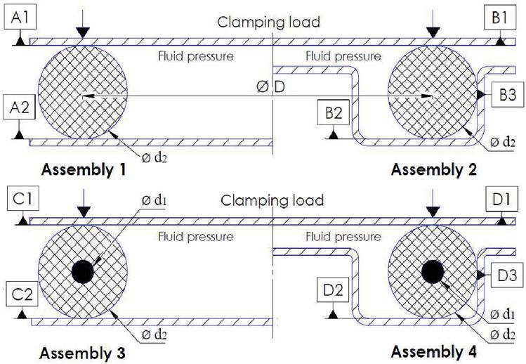
Figure 1 Assembly of the O-ring between two plates (Assembly 1), Assembly of the O-ring in a groove (Assembly 2), Assembly of the reinforced O-ring between two plates (Assembly 3), Assembly of the reinforced O-ring in a groove (Assembly 4).
2 Modeling of O-ring Assemblies
For the past 60 years, O-ring modeling has been a topic of study in the international literature that has attracted great interest. The complexity of the nonlinear behavior of the O-ring material as well as the very sensitive dependence on changes in the mounting conditions can be difficult to implement in the numerical analysis.
O-rings are installed in different ways depending on the location and environmental requirements. In this study, we investigate the mechanical behavior of a flange O-ring with static axial mounting when the clamping load and fluid pressure are applied. This work proposes the modeling of four different assemblies, Figure 1, in which the O-ring is stressed by a compression load, which represents the installation force, and by the pressure of the fluid that is retained inside the assembly. The ISO 3601 standard [14] was used to determine the size of the O-ring and the rectangular groove. The mechanical and geometrical characteristics of the four couplings are given in Table 1.
Table 1 Mechanical and geometrical characteristics of the assemblies
| Symbol | Designation | Contact |
| A1 | Top surface | Classic O-ring-plates |
| A2 | Bottom surface | |
| B1 | Top surface | Classic O-ring groove |
| B2 | Bottom surface | |
| B3 | Lateral surface | |
| C1 | Top surface | Reinforced O-ring-plates |
| C2 | Bottom surface | |
| D1 | Top surface | O-ring reinforced groove |
| D2 | Bottom surface | |
| D3 | Lateral surface | |
| Values | ||
| Compression ratio | ||
| O-ring inner diameter | 16.35 mm | |
| Diameter of the metal core | 0.25mm | |
| Cross-sectional diameter of the joint | 2.65 mm | |
| Young’s modulus of the elastomer | 13.8 MPa | |
| Young’s modulus of metal core | 210000 MPa | |
| Clamping force | 700 N | |
| Friction coefficient | 0.2 | |
| Mooney-Rivlin coefficients | 2.334/0.034 |
The greatest difficulty in modeling elastomers is the nonlinear behavior [15]. Thus, the laws of mechanical behavior must be formulated in the context of a large deformation model [16]. One of the frequently encountered models to describe the mechanical behavior of elastomers is the Mooney-Rivlin hyperelastic model [17].
The finite element models of the assemblies in this study were performed with axisymmetric elements using ANSYS software [18]. All the components of the assemblies are meshed by rectangular elements to better manage the contact between the supposedly rigid supports and the flexible joint. The O-ring is modeled by a disk with 2D 4-node planar elements PLANE182 (The number of elements used is 2700 elements with 5167 nodes). The type of analysis is a static analysis with geometric nonlinearity (NLGEOM, ON, and SOLCONTROL, ON). The contact elements, CONTA171 and TARGE169, are used to simulate the reaction between elements that are in contact. The contact elements are constructed using the 2D 2-Node Surface-To-surface contact approach. A friction interaction is defined for the contact pairs (via the MP command). The contact formulation used is the “Lagrange multiplier on contact-normal and penalty-on-tangent” (KEYOPT (2) 3 on CONTA171). The fluid penetration pressure is applied to the contact (via the SFE command with the load key value LKEY set to 1).
The proposed model of the reinforced O-ring contains two materials. The first one represents the metal core. The second one defining the envelope is made of elastomers. The two studied seals undergo successively two loads. Axial compression is performed by a uniformly distributed clamping force on the top plate, then a fluid pressure is applied on the inner surfaces of the seal. The displacements of the groove and the bottom plate were canceled in all directions. Figure 2 shows the mesh configuration used for both seals.
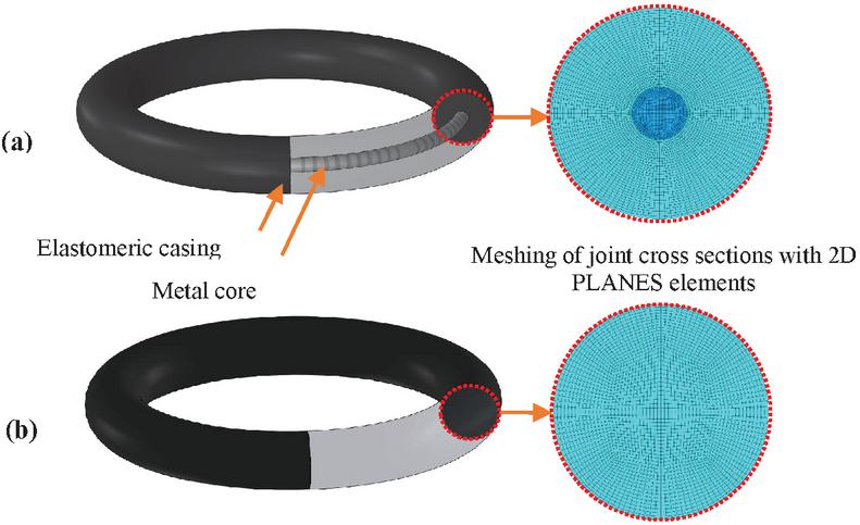
Figure 2 Mesh size of O-rings. (a) Reinforced O-ring (b) Standard O-ring.
3 Results and Discussion
In assemblies with O-rings, sealing is achieved by compression of the O-ring, which produces contact pressure at the joint-structure contact surfaces. Sealing is most effective when the seal-structure contact pressure is high. When fluid pressure is applied, the seal will undergo deformation which may be inadmissible. To avoid this excessive deformation, the conventional O-ring is usually housed in a groove with a rectangular cross-section. The radial deformations shown in Figure 3 demonstrate the importance of the location of the O-ring in a groove. It is clear that for a given clamping force and fluid pressure, the axial deformation when placing the conventional O-ring between two plates is greater than when using a reinforced O-ring.
The O-ring is used to prevent leakage in pressurized assemblies. During assembly, the seal is compressed axially to create an initial contact pressure distribution capable of theoretically providing a seal. When fluid pressure is applied, the interaction between the various components of the assembly causes the shape and values of the contact pressure to change. To analyze the effect of fluid pressure on the behavior of the two seals in the studied assemblies, different fluid pressures between 0 and 4 MPa are applied. Figure 4 shows the contact pressure distributions at the contact surfaces defined in Figure 1 for a clamping force of 700 N and three values of fluid pressure. This figure shows the effect of installing a metal core inside the elastomeric O-ring. Regardless of the contact area, the maximum contact pressure increases as the fluid pressure increases. It is noted that, for given fluid pressure, the contact pressure when placing the seal in a groove is greater than that produced between two plates. In addition, the contact pressure at the surfaces relative to the reinforced O-ring is greater than that produced at the contact surfaces of the conventional O-ring. These results confirm that installing a reinforced O-ring in a groove generates more contact pressure. From this point on, only the data obtained for mounting the conventional O-ring in the groove and mounting the reinforced O-ring between two plates and in the groove will be presented to evaluate the use of the reinforced O-ring and the groove.
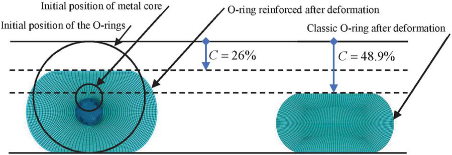
Figure 3 Progression of the deformation of the studied O-rings for a clamping force of 700 N and a fluid pressure of 0.75 MPa.
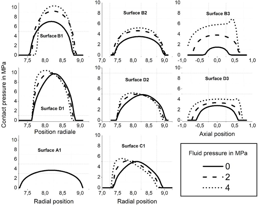
Figure 4 Comparison of the variation of contact pressure distribution as a function of fluid pressure with a clamping force of 700 N.
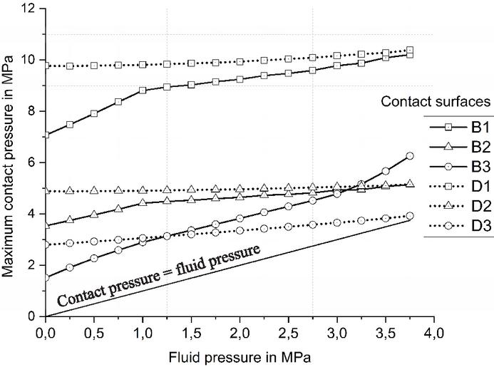
Figure 5 Variation of the maximum contact pressure as a function of the variation of the fluid pressure for a clamping force of 700 N.
Figure 5 shows the variation of the maximum contact pressure at the contact surfaces of the grooved assemblies as a function of the fluid pressure. It is obvious that the maximum contact pressure is always higher than the applied fluid pressure. On the other hand, the maximum contact pressures at the surfaces D1 and D2, related to the reinforced O-ring, are greater than those at the surfaces B1 and B2, produced by the conventional O-ring in grooved assemblies. However, there is not much effect of the variation of the fluid pressure on the contact pressure values at the contact surfaces of the assembly 4. The physical interpretation of the above is that an elastomeric O-ring, with an initial compression ratio, exposed to fluid pressure, behaves like a liquid of very high surface tension, maintaining the clamping force and transferring the fluid pressure into sealing contact pressure [19]. From these remarks, it can be deduced that the assembly with a reinforced O-ring is more tightly sealed than that with a conventional O-ring.
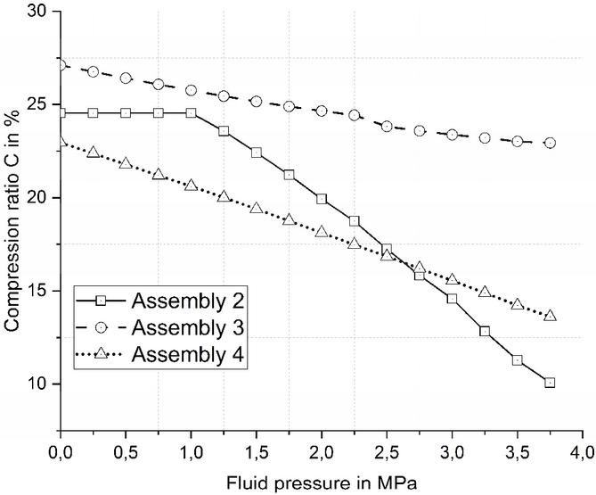
Figure 6 Variation of the compression ratio as a function of the fluid pressure for a clamping force of 700N.
Figure 6 shows the evolution of the compression ratio C, obtained for the three assemblies 2, 3, and 4 as a function of the fluid pressure. The compression ratio decreases with increasing fluid pressure. It is also observed that the rate of decrease of the compression ratio of the seal is more important in the case of the conventional O-ring after a slight initial stabilization for low fluid pressures. This is expected, given the presence of the metal core which increases the resistance of the reinforced O-ring to deformation. A comparison of the curves for assemblies 3 and 4 shows that the groove decreases the amount of compression ratio required to tighten the seal. From these remarks, it can be concluded that mounting the reinforced O-ring in a groove can further improve the sealing of the assembly with a moderate compression ratio.
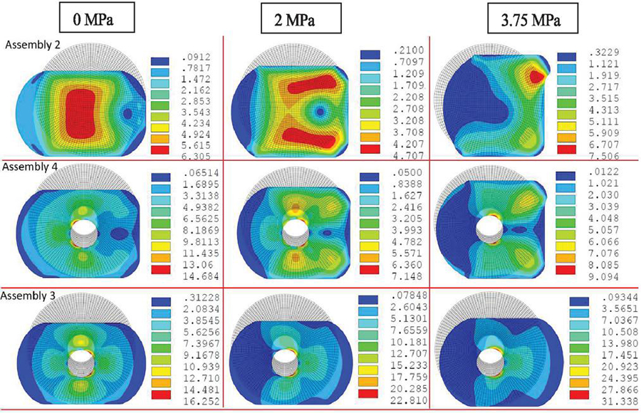
Figure 7 Variation of the Von-Mises stress distribution as a function of fluid pressure for a clamping force of 700N.
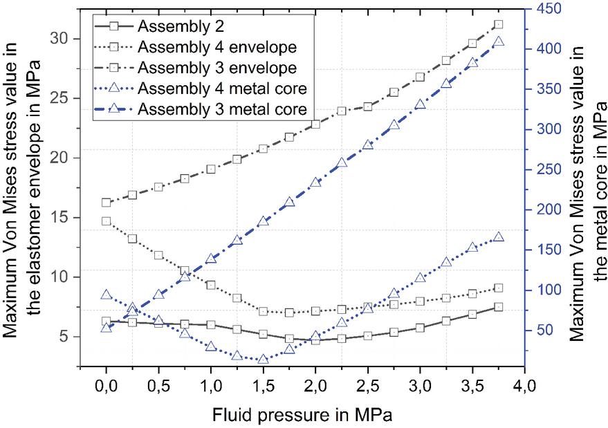
Figure 8 Variation of the maximum Von Mises stress as a function of fluid pressure for a clamping force of 700 N.
During operation, both of the studied seals undergo a large amount of deformation which can damage them and consequently cause leaks. Figure 7 shows the distribution of the Von Mises stress inside the seal as a function of the fluid pressure for a clamping force of 700 N. It is clear to notice that the two seals do not react in the same way and the stress inside the reinforced O-ring is greater than that of the conventional. It can be seen that the metal core produces symmetry with respect to the horizontal median plane of the Von Mises stress distribution inside the elastomer shell. On the other hand, when the fluid pressure is applied and its value increases further, the zone where the stress is maximum moves towards the outside of the conventional O-ring to the side of the extrusion gap. This can lead to the appearance of striations and cracks on the outer surface of the seal and also cause deterioration of the seal and consequently leakage.
Figure 8 shows the variation of the maximum value of the von Mises stress inside the two seals as a function of the fluid pressure for a clamping force of 700 N. It can be seen that mounting the reinforced O-ring between two plates generates higher stresses than the one with a groove. The comparison between the two studied seals shows that the metal core increases the value of the maximum Von Mises stress inside the elastomer shell. It is noted that the difference between the two cases remains relatively small as the fluid pressure increases. In conclusion, mounting in a groove can protect the two studied seals against high stresses and thus the risks of their deterioration and the probability of their failure.
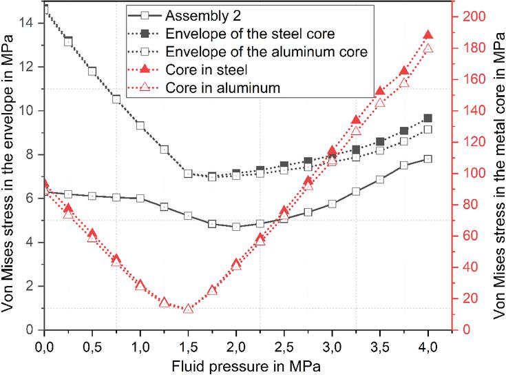
Figure 9 Effect of the metal core material on the evolution of the maximum value of the Von Mises stress.
Figure 9 shows the effect of the core material on the evolution of the maximum Von Mises stress inside the O-ring, in this part, two materials were chosen whose mechanical properties are given in Table 2. For the same variation of fluid pressure, we notice a small difference between the maximum equivalent Von Mises stress generated when using either aluminum or steel. This result is very interesting and shows that the weight of a reinforced O-ring can be reduced by using an aluminum core instead of a steel one.
Table 2 Mechanical characteristics of the metal core material
| Steel | Aluminum | |
| Young’s modulus in MPa | 210000 | 69000 |
| Poisson’s ratio | 0.3 | 0.346 |

Figure 10 Effect of varying the diameter of the metal core on the value of the maximum Von Mises stress in the elastomer shell for a 20% compression ratio.

Figure 11 Effect of the variation of the diameter of the metal core on the maximum value of the contact pressure for a compression ratio of 20%.
To examine the effect of the metal core size on the variation of the maximum contact pressure and the maximum value of the von Mises stress inside the elastomer shell of the reinforced O-ring, four values of the metal core diameter are used which represent 15, 20, 40 and 50% of the total O-ring diameter. Figure 10 shows the variation of the maximum Von Mises stress in the shell as a function of fluid pressure for the different diameters when the reinforced O-ring is placed in a groove. It can be seen that the larger the diameter of the metal core, the greater the maximum Von Mises stress. The decrease of the metal core diameter has a positive influence on the maximum Von Mises stress inside the reinforced O-ring for high fluid pressures.
Figure 11 shows the variation of the maximum contact pressure, at the level of the surfaces D1, D2, and D3 relative to the assembly of the reinforced O-ring in a groove, for the various diameters of the metal core and for a compression ratio of 20%, according to the pressure of the confined fluid. It can be seen in this figure that the values of the maximum contact pressure increase with increasing fluid pressure. The value of this increase is characterized by the value of the diameter of the metal core. The larger the diameter of the metal core, the smaller the variation of the maximum contact pressure as a function of the fluid pressure on all contact surfaces. On the other hand, the comparison between the different diameters of the metal core indicates that the maximum contact pressures generated by the small diameter of 15% are greater than those produced by the diameter of 20%. In conclusion, the 15% diameter of the metal core is the most suitable choice to guarantee low stress and high contact pressure.
4 Conclusion
This work is devoted to the study of the mechanical and leakage behavior of pressurized assemblies equipped with a conventional O-ring and a metal core reinforced seals, and which are placed either between two plates or in a rectangular groove.
Four axisymmetric models are developed using ANSYS software to simulate the behavior of these assemblies under real operating conditions.
The combined effect of clamping load and fluid pressure was analyzed for all four models. The results showed that the assembly mode significantly modified the value of the equivalent Von Mises stress inside the two studied joints as well as the value of the strains.
Moreover, the results showed that the O-ring reinforced by a metal core generates more pressure on all contact surfaces and less deformation compared to the conventional seal and thus limits the risk of leakage. On the other hand, under the same loading conditions, the maximum Von Mises stress is lower in the case of the conventional O-ring, when both seals are placed in the groove.
Finally, original experiments are to be carried out allowing, on the one hand, the visualization of the behavior of the two joints studied in the four installations and, on the other hand, the access to other quantities such as measurements of the pressure distribution and contact dimensions, friction, stresses, and leaks.
Disclosure Statement
No potential conflict of interest was reported by the authors.
References
[1] P. B. Lindley, “Compression characteristics of laterally-unrestrained rubber O-rings,” J. Inst. Rubber Ind, vol. 1, no. 4, pp. 209–213, 1967.
[2] S. P. Timošenko and J. N. Goodier, Theory of elasticity. McGraw-Hill, 1951.
[3] E. Dragoni and A. Strozzi, “Analysis of an Unpressurized, Laterally Restrained, Elastomerio O-Ring Seal,” Journal of Tribology, vol. 110, no. 2, pp. 193–200, 1988.
[4] E. Dragoni and A. Strozzi, “Theoretical analysis of an unpressurized elastomeric O-ring seal inserted into a rectangular groove,” Wear, vol. 130, no. 1, pp. 41–51, 1989.
[5] A. Karaszkiewicz, “Geometry and Contact Pressure of an O-Ring Mounted in a Seal Groove,” Industrial and Engineering Chemistry Research, vol. 29, no. 10, pp. 2134–2137, 1990.
[6] A. F. George, A. Strozzi, and J. I. Rich, “Stress fields in a compressed unconstrained elastomeric O-ring seal and a comparison of computer predictions and experimental results,” Tribology International, vol. 20, no. 5, pp. 237–247, 1987.
[7] M. Diany and H. Aissaoui, “Analytical and Finite Element Analysis for Short term O-ring Relaxation,” Applied Mechanics and Materials, vol. 61, no. 6, pp. 478–482, 2011.
[8] H. Aissaoui, M. Diany, and J. Azouz, “Numerical simulation of radial and axial compressed eleastomeric o-ring relaxation,” Global Journal of Researches in Engineering Mechanical and Mechanics Engineering, vol. 12, no. 4, 2012.
[9] E. Bahloul, M. Diany, H. Aissaoui, E. Boudaia, J. Azouz, and M. Mabrouki, “Finite element analysis of the O-ring behavior used in static sealing assembly,” pp. 106–108, 2019.
[10] E. El Bahloul, M. Diany, H. Aissaoui, E. Boudaia, and M. Mabrouki, “Analysis of the Sealing Performance of a Concave O-Ring Groove,” International Review of Mechanical Engineering, vol. 15, no. October, pp. 530–537, 2021.
[11] J. X. Li, P. F. Liu, S. B. Wang, and J. X. Leng, “Finite Element Analysis of O-ring Sealing Performance of Manned Submersible Viewports,” Journal of Failure Analysis and Prevention, vol. 20, no. 5, pp. 1628–1637, 2020.
[12] R. H. Warring, Seals and sealing handbook. 1981.
[13] E. M. EL Bahloul, M. Diany, H. Aissaoui, E. Boudaia, and M. Mabrouki, “Finite Element Analysis of O-ring Performance Reinforced by a Metallic Core,” International Journal of Fluid Power, vol. 23, pp. 237–252, 2022.
[14] ISO 3601, Fluid power systems – O-rings. Part 1: Inside diameters, cross-sections, tolerances, and designation codes. Part 2: Housing dimensions for general applications. Part 3: Quality acceptance criteria. Part 4: Anti-extrusion rings (back-up rings). Part 5: Suitability of elastomeric materials for industrial applications.
[15] J. Mackerle, “Rubber and rubber-like materials, finite-element analyses and simulations, an addendum: A bibliography (1997–2003),” Modelling and Simulation in Materials Science and Engineering, vol. 12, no. 5, pp. 1031–1053, 2004.
[16] B. Omnès, Comportement mécanique des joints toriques. Centre technique des industries mécaniques., 2016.
[17] L. Mullins, Engineering With Rubber., vol. 17, no. 12. 1987.
[18] ANSYS, ANSYS Standard Manual, Version 19.2.
[19] H. K. Müller and B. S. Nau, Fluid sealing technology: principles and applications. Routledge, 2019.
Biographies

El Mehdi El Bahloul is currently a Ph.D. student in the Industrial Engineering Laboratory at Sultan Moulay Sliman University, Faculty of Sciences and Technology in Beni Mellal, Morocco. He is also a High school teacher of Engineering and mechanical sciences at Tighnari Technical High School. He received his master’s degree in mechanical engineering from Higher Normal School of Technical Education, Mohammed V University in Rabat, Morocco. His main field of research is mechanical engineering, structural mechanics and material sciences.

Hicham Aissaoui is a Professor in the Faculty of Sciences and Technologies in Electrical Engineering department at the University of Sultan Moulay Slimane, where he has been a faculty member since 1996. He completed his Ph.D. at University Mohamed V and got his Habilitation at the University of Sultan Moulay Slimane. His research interests stability analysis and non-linear control. He had collaborated actively with researchers in several other disciplines of signal and image analysis, particularly medical images on problems at tumor diagnostics.

Mohammed Diany Ph.D. is a Professor at Mechanical Engineering Department, University Sultan Moulay Slimane, Faculty of Sciences and Technics, Beni Mellal, Morocco. His Ph.D. thesis in 2010 was on the subject of Characterization and Modelling of Stuffing Box Packings and completed at École de Technologie Supérieure, Montreal, Canada. His researches are focused on Mechanical Engineering, Structural Mechanics, and Material Sciences.

Elhassan Boudaia is an associate Professor at the Mechanical Engineering Department of Higher School of Technology of Casablanca, Morocco. His Ph.D. thesis in 2007 was on the subject of a meshless and finite element methods analysis for elastoplastic contact problems with friction. His current research activities are multidisciplinary and focus mainly on design approaches and reliability analysis, especially in structural engineering. Using the elastoplastic analysis and the meshless or the finite element method, he has published with his co-workers’ many works on the reliability assessment of structures, especially in the non-associated elastoplastic area.

Mustapha Mabrouki currently works at the Physics Department (Full professor), University Sultan Moulay Slimane, Faculty of Sciences and Techniques, Beni Mellal, Morocco. Mustapha does research in Smart grids and smart cities (optimization models for balancing energy), Photovoltaic Materials Synthesis and Integration, Phosphates and derivatives, Biotechnology and Microbiology. My current projects are 1-‘PROPRE.MA’. Build photovoltaic yield maps of grid connected mono, poly and amorphous PV modules for all Morocco with land calibration on 20 identical plants. 2-AFM project 3-Phosphate project 4-Solar Decathlon Africa2019 competition.
International Journal of Fluid Power, Vol. 24_4, 625–642.
doi: 10.13052/ijfp1439-9776.2441
© 2023 River Publishers