Viable Energy Recovery Strategies Through Advanced Directional Control Valve
Gianluca Ganassi1,*, Davide Mesturini1, Cesare Dolcin1, Antonella Bonavolontà2, Emma Frosina3 and Pietro Marani4
1Walvoil SpA, via Adige 13/D, 42124 Reggio Emilia, Italy
2UniNA FPRG, Università degli Studi di Napoli “Federico II”, via Claudio 21, 80125 Napoli, Italy
3UniSannio DING, Università degli Studi del Sannio, piazza Roma 21, 82100 Benevento, Italy
4C.N.R.-STEMS, Via Canalbianco 28, 44124 Cassana (FE), Italy
E-mail: ganassi.g@walvoil.com; mesturini.d@walvoil.com; dolcin.c@walvoil.com; antonella.bonavolonta@unina.it; frosina@unisannio.it; pietro.marani@stems.cnr.it
*Corresponding Author
Received 01 September 2022; Accepted 23 January 2023; Publication 29 April 2023
Abstract
The demand for more efficient machines is pushing hydraulic manufacturers to develop a new generation of systems capable of energy saving and recovering. An advanced flow sharing directional control valve with downstream compensation reduces meter-out pressure losses and recovers energy both in combined movements and with overrunning loads. Tests carried out on a prototype on a test bench confirm the proper functioning of the concept and allow tuning its lumped parameters numerical model. A control strategy based on keeping the optimal compensator position allows computing the maximum theoretical recovery. The simulation of a mini-excavator digging cycle shows the energy saving and recovery compared to a standard flow sharing system.
Keywords: Directional control valve, flow sharing, downstream compensation, energy saving, energy recovery.
1 Introduction
Among sustainable development goals of world leaders, the pillars of innovation, sustainable cities and responsible consumption will guide the design of new off-road vehicles in the forthcoming years. Electrification and hybridization find wider applications as regulations are increasingly restricting waste gas emissions and, in some cases, do not even allow ICE use (i.e. construction sites in city centre [1]): various studies predict a significant increase of battery powered off-road vehicles over the next few years [2, 3].
While some OEMs imagines the use of purely electromechanical devices for the actuation of small sized vehicles [4], hydraulics will clearly continue to play a central role in the most of applications, thanks to its practicality and unparalleled power density [5].
On the other hand, hydraulics will progressively evolve towards more efficient solutions, to allow cost reduction and greater autonomy of battery-powered vehicles.
In fact, several works have highlighted how traditional hydraulic systems often have low levels of efficiency and, in particular, how a considerable part of the energy losses is concentrated in the directional control valves. The concept of “valveless” decentralized system has then been developed to provide the maximum efficiency in simultaneous operations and the optimal energy recovery [6–8]. The drawback of these systems is the high installation cost, hardly affordable by the mobile market, together with a multitude of technical complexities [9, 10] and noticeable overall dimensions.
The centralized hydraulic systems remain therefore the most reliable and cost-effective solution, that can be improved through independent metering layout [11] or digitalized design [12]. In those cases as well, the component cost is significantly higher than traditional ones and no recovery and saving opportunities can be fully exploited.
This work shows an innovative design of a centralized Directional Control Valve, based on the well-known Load Sensing principles, capable of significant reduction in metering losses and remarkable energy recovery from both inertial loads and simultaneous operations.
Traditional flow sharing systems are usually composed of a DCV and a load-sensing pump. LS principle guarantees that the speed of the actuator does not depend on the load (i.e. work port pressure) but only on its spool stroke; flow sharing ensures that in case of pump saturation the flow given by the pump feeds all working actuators proportionally. Each section of a flow sharing DCV has its own compensator, whose function is to keep the pressure drop across meter-in notches equal to the pump margin in all working sections, throttling the flow and therefore dissipating energy.
The new DCV is a flow-sharing type, where a “downstream compensator” is placed on each working section, on the return line from actuators. The downstream compensator layout has already been seen in some commercial valves and in some innovative works [13, 14], although they use it mainly for controllability and only partially exploit its intrinsic recovery possibilities.
The particular 3-way design of the downstream compensator has been explained in [15]; the present work adds a different piloting method and a fully developed recovery strategy.
A first benefit is that the downstream compensator allows recovering energy during simultaneous movements in the sections at lower load. Moreover, the local compensator provides the correct backpressure to prevent any cavitation in presence of overrunning loads; the actuator speed is independent on the load and it is not necessary to throttle the spool meter-out notches. Last, the downstream compensator allows recovering energy from overrunning loads, thanks to an external pilot X that feeds LS line, making the section work as if it was dependant also when it works alone. The following paragraphs will show all these features and the architecture of the new DCV.
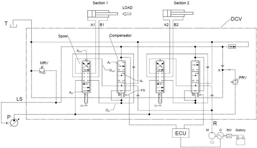
Figure 1 Hydraulic schematic with DCV and example of recovery system.
2 System Architecture
Referring to Figure 1, each of the two sections of DCV consists of a 6-way spool and a 3-way compensator. Oil from variable displacement load-sensing pump P feeds in parallel the meter-in area A of each spool. Depending on the spool position, oil goes to the relative actuator (cylinder or motor) A side in pos.1 (or B side in pos.2) through a check valve in channel D downstream the meter-in; then oil returns from the actuator B side in pos.1 (or A side in pos.2) to the spool meter-out area A and goes to tank T.
The 3-way compensator located downstream the meter-out D sends the return flow Q in a preferred way through a check valve towards a regenerative line R, otherwise to tank T. A spring of negligible force keeps the local compensator in open position. The signal downstream the meter-in pushes the local compensator to open, while the load sensing signal LS acts in the closing direction.
Only when the local compensator is fully open, it sends its pressure signal D into LS line; when the local compensator is throttling the flow Q, it copies the LS signal in D. The result is that all meter-in areas see the same pressure drop p–p equal to the pump margin Dp.
A low-pressure pilot source X (15 bar for example) feeds or not the LS line depending on the spool position. In Figure 1, for example when spool 1 feeds the base side A where the load is resistant like in boom up, pilot source X dumps to tank and does not feed the LS line. If the spool feeds rod side B where the load is overrunning like in boom down, pilot source X pressurizes and feeds the LS line. Hence, even when an actuator is working alone, the pilot source X makes the compensator throttle and thus potentially recover.
The recovery system in Figure 1 includes a hydraulic motor M, coupled to an AC generator G, which charges a Battery thanks to an inverter INV. This recovery system layout, already discussed in previous works [16], is now provided with a control logic that maximizes the efficiency. Each local compensator sends its position by means of a position sensor PS to an Electronic Control Unit ECU, which manages the generator G torque so that the active local compensators are maintained in the position of maximum recovery efficiency.
3 New Directional Control Valve: Working Principle
The relevant operating modes are listed and described in the following paragraphs 3.1–3.3, respectively about: one section with resistant load generating the LS signal; two sections with resistant loads, one generating the LS (dominant) and the other copying it (dependant); one section with overrunning load, copying the LS (made dependant by pilot pressure X). All the other conditions (three or more sections) are a combination of the previous ones.
3.1 Actuation of a Single Section with Resistant Load
Referring to Figure 1, let us assume that the spool in section 1 is actuated in PA/BT position (cylinder extends) and that the force on the actuator pushes the rod, i.e. load is resistant. Pressure signal downstream the meter-in D is equal to the load p and opens the local compensator, therefore the line D downstream the meter-out is connected to tank T. The signal D feeds the LS line, therefore p is equal to p. The pressure drop across the meter-in notches A of the spool is equal to the pump margin Dp, which means that the work port flow Q is proportional to the meter-in area A and therefore depends on the spool stroke only (load sensing principle):
| (1) |
In this condition, there is no difference compared to a traditional load sensing flow sharing valve; there are no recovery opportunities, therefore the compensator is fully open to tank, minimizing the pressure drops and operating pressure.
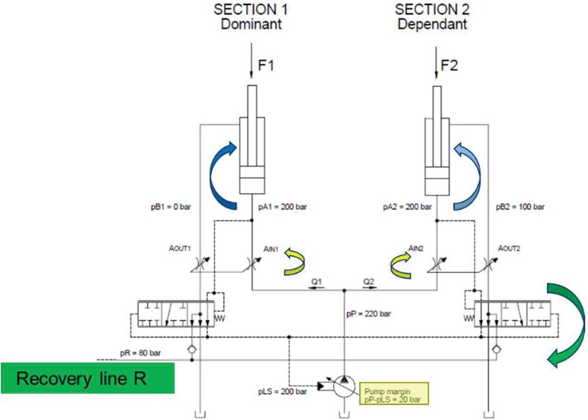
Figure 2 Simultaneous actuation of two sections with resistant loads – simplified schematic.
3.2 Simultaneous Actuation of Two Sections: One at Higher Resistant Load (Dominant Section) and the Other at Lower Resistant Load (Dependant Section)
Referring to Figure 2, let us assume that both spools are actuated in PA/BT position (cylinders extend) and that the forces on both the actuators push the rods, i.e. loads are resistant. Let pressure at work port A1 p be higher than pressure at work port A2 p.
Section 1 is dominant and its compensator works exactly as described in paragraph 3.1: local compensator is fully open and LS pressure p is equal to work port pressure p.
Section 2 is dependant and its compensator copies the LS pressure p in D downstream the meter-in, throttling the meter out flow Q.
Pressure drop across meter-in notches is equal to pump margin Dp in both sections, therefore Equation (1) applies to both. This means that the work port flows depend on the spool stroke only (load sensing principle) and decrease proportionally in case of pump saturation (flow sharing principle).
The local compensator design is such that the connection between D and T closes at approximately 50% of its max stroke, while the connection between D and R closes at approximately 90% of its max stroke. The compensator of dependant section 2, which throttles the return flow Q, feeds in a preferred way the recovery line R if pressure in D is higher than in R, otherwise the tank T.
Therefore, it is possible to recover energy during simultaneous movements in dependant sections, according to pressure in R: if pressure in R is lower than D recovery is possible, otherwise it is not.
Note that during a simultaneous actuation of two sections, it is not possible to recognize the dominant section by simply looking at the work port pressures p and p, since they are identical in all sections. It is necessary to look at the work port difference p–p and p–p.
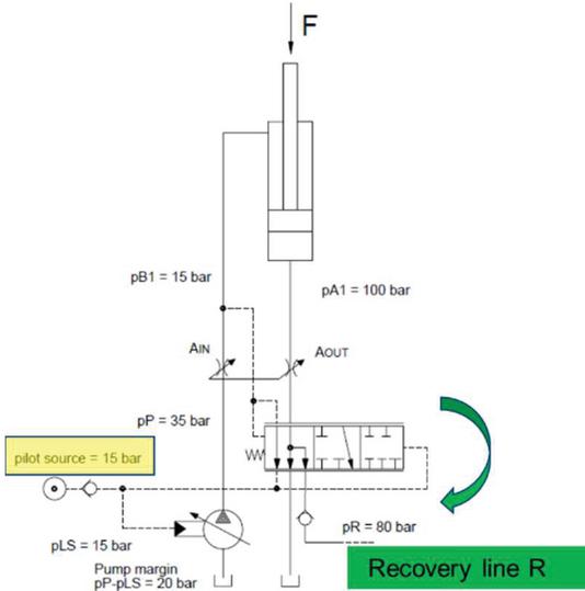
Figure 3 Single section with overrunning load – simplified schematic.
3.3 Actuation of a Single Section with Overrunning Load
Traditional flow sharing valves often manage overrunning loads with a high backpressure generated by the meter-out notches, to prevent the cavitation of the actuator. Spool design has to consider the worst case, the highest overrunning load; therefore, when the load is low, energy dissipation occurs. In the new DCV, downstream compensator performs a variable restriction, which covers the function of the spool meter-out notches; therefore, spool meter-out area A can be larger, with a consequent energy saving when the load is low, respect to a traditional load sensing valve.
Referring to Figure 3, let us assume that: the spool in section 1 is actuated in PB/AT position (cylinder retracts); the force on the actuator pushes the rod, i.e. load is overrunning; the meter-out area A is large. Thanks to the logic present on the spool, pilot pressure X feeds LS line, thus the local compensator works as if the section was dependant: the local compensator copies the LS pressure in D downstream the meter-in. Pressure drop across meter-in notches is equal to pump margin Dp (load sensing flow sharing principle). The meter-out flow Q goes in a preferred way into the R line, if the pressure in R is lower than in D; otherwise, it goes to tank T. Recovery is possible depending on the pressure in R: if the pressure in R is lower than D the recovery is possible.
In conclusion, the new DCV allows to save energy, having larger meter-out notches compared to a traditional flow-sharing valve, and to recover energy with overrunning loads.
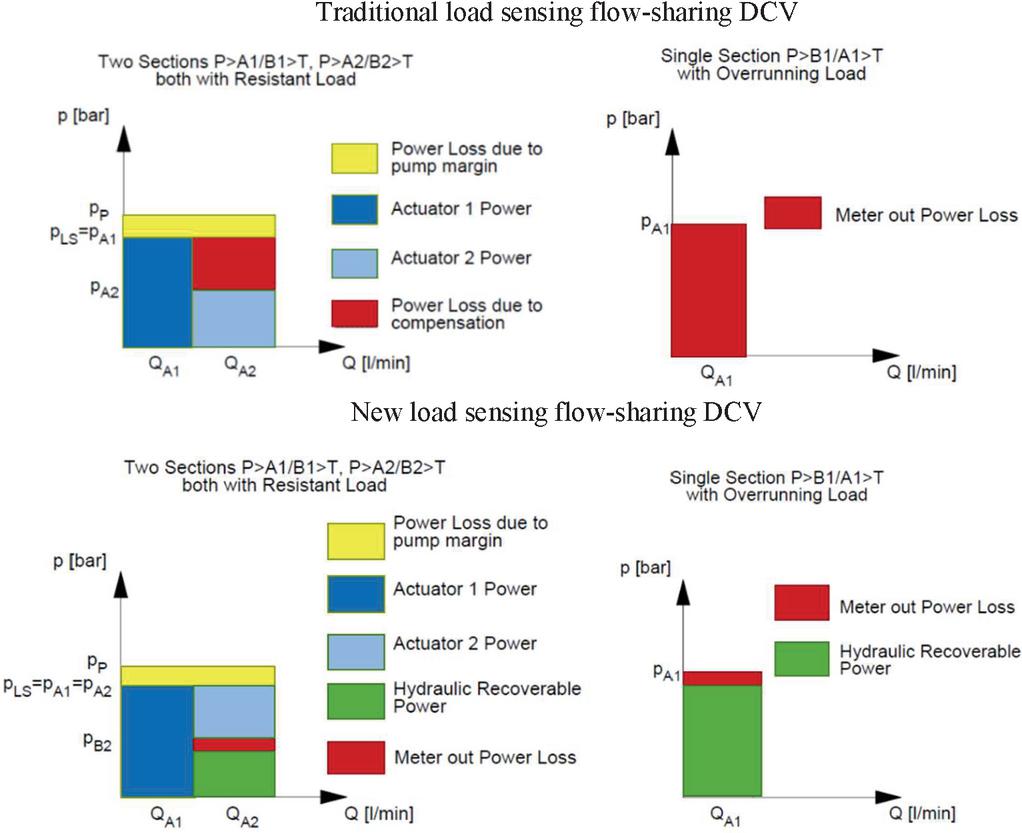
Figure 4 Power Diagram Comparison between traditional and new DCV.
3.4 Power Diagram Comparison
Figure 4 shows the power that the new DCV intends to recover during compensation or when lowering a load, compared to the power loss of a Traditional Load Sensing Flow Sharing DCV.
From hydraulic point of view, the maximum theoretical recovery corresponds to the power loss occurring in conventional LS systems due to compensation, or to the power loss due to spool meter-out with overrunning loads.
It should be finally noted that as for traditional DCV, the new DCV as well allows to apply superimposed methods (not in the scope of the present work, though) to reduce the pump margin power losses, such as variable stand-by [17, 18] or pump positive control [19].
4 Experimental Activities and Simulation Model
A prototype of the new DCV was manufactured and tested on a test bench in steady state conditions and as depicted in Figure 5, the DCV was installed with relevant measurement instruments, such as several pressure transducers, flow meters and stroke transducers. In order to simulate loads of resistant type, the work ports were shortcut, with in between a variable setting relief valve. To simulate overrunning loads, a dedicated cylinder was applied, provided with an external load source.

Figure 5 Prototype of two sections DCV on test bench.
Since the analysis of the performance of the DCV is possible by controlling the pressure in R line, a relief valve replaced the recovery system (motor M, generator G, inverter INV and Battery) to simplify the activity.
First, the tests verified and confirmed the load sensing flow-sharing properties of the DCV, then its energy recovery capabilities. In parallel, models of each test were created and tuned in the lumped parameters software Simcenter Amesim. The following paragraphs describe the procedures of tests with energy recovery, the relative simulation models and the results.
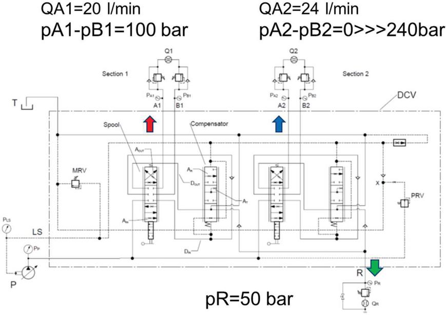
Figure 6 Hydraulic schematic of pressure compensation test with resistant loads.
4.1 Pressure Compensation of Two Sections with Resistant Loads
In pressure compensation test, the two spools are fixed at a specific stroke, so that their work port flows are constant. Load of section 1, which is equal to p–p, is set at 100 bar; the load of section 2 p–p varies from zero to relief pressure. Recovery line R pressure is set at a 50-bar constant value.
The hydraulic schematic of the test rig shown in Figure 6 is reproduced in the Amesim environment (Figure 7), modelling two sections with resistant loads and energy recovery.
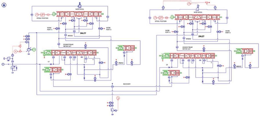
Figure 7 Model of two sections with resistant loads.
Figure 8 presents the measured flows as a function of the load of section 2, together with the simulation results of pressure compensation.
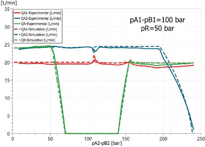
Figure 8 Experimental vs simulation result of pressure compensation with resistant loads.
The two work-port flows Q and Q are constant, except when section 2 reaches relief valve setting, confirming the flow sharing property of the new DCV. Section 1 is dominant up to 100 bar, therefore return flow Q is recovered in R; section 2 is dominant above 100 bar, therefore return flow Q is recovered in R. The flow Q is maximum, equal to the return flow, when the difference between the loads of the two sections is equal or higher than pressure p according to the following condition:
| (2) |
Figure 8 suggests that full recovery is possible if pressure p is lower than the difference between the loads. In this condition, the local compensator of dependant section opens passage towards recovery line R. While if p is higher than the difference between the loads, the oil begins to flow to T, reducing the recovered power down to zero.
4.2 Single Section Actuation with Overrunning Load
In the actuation of a single section with overrunning load, the spool is fixed to a specific stroke, so its work port flow is constant. Referring to Figure 9, that shows the hydraulic schematic of the test, let the spool be in position PB1/A1/T. Overrunning load is constant. During the test, the pilot pressure p, activated by the spool displacement, defines the LS pressure. During the test, the pressure p in the recovery line R is regulated with a ramp from zero to max possible value.
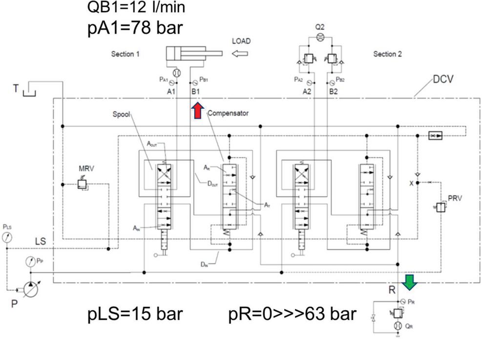
Figure 9 Hydraulic schematic of section 1 actuation with overrunning load.
Figure 10 presents the experimental and simulation results as a function of time.

Figure 10 Experimental vs simulation results of single actuation with overrunning load.
The return flow Q is constant, confirming that what happens in recovery line R does not affect the flow regulation. Pressure p is equal to 15 bar approximately, that is actually the value of the pressure source X feeding the LS line. Pressure in work-port A1 is 78 bar due to the overrunning load. The recovery is possible if p is lower than return pressure p: in this case, Q is equal to Q. If p is higher than p, recovery becomes less advantageous or null.
Let us define the efficiency of compensator recovery as the ratio between the hydraulic-recovered power and the hydraulic-available power in return line, according to the following formula:
| (3) |
Figure 11 plots the efficiency of compensator recovery , the recovered power and the compensator stroke, referring to the same test described in Figure 10.

Figure 11 Efficiency of compensator recovery, compensator stroke and recovered power in single actuation with overrunning load.
The recovered power and the efficiency are maximum before the compensator opens T line at time 11 s, when compensator stroke decreases from 80% to 50%, confirming that the control strategy based on the measure of the compensator stroke is viable.
5 Energy Recovery Strategy
Once the recovered flow is available in the line R, its management depends on the choices of the equipment manufacturer. It is possible to regenerate the recovered flow into the system directly, to store it in a hydraulic accumulator, or to transform it in electrical energy and store in a battery.
Following the simulations and tests run during this work, it was evident that this last solution provides the best opportunity to fully exploit the energy flux collected by the new DCV.
Particularly, an electronic control of the backpressure p based on the control of the absorbed torque of the electric motor allows the maximum recovery and avoids excessive dissipation through the downstream compensators.
The whole system described in Figure 1 (including a hydraulic motor M, coupled to an AC generator G, which charges a Battery thanks to an inverter INV), has been further investigated and simulated defining a control strategy to optimally vary the pressure in line R, using each local compensator position as the feedback to control the current on generator G and thus the pressure in line R.
Based on Figure 6 circuit, an additional test was run operating two sections simultaneously and progressively increasing the pressure p. The analysis of the efficiency of the compensator recovery as a function of compensator stroke shows that the local compensator has a wide range where efficiency is maximal, see Figure 12.
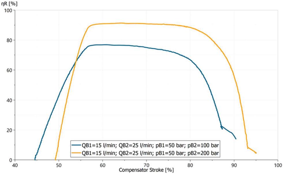
Figure 12 Experimental results of pressure compensation, varying p.
This outcome suggests the feasibility of a control strategy based on the feedback of local compensator stroke. In fact, the proposed control strategy consists on keeping the active compensators stroke close to a target value where recovery efficiency is maximum, which corresponds to a position of opening towards R and closing towards T.
More into detail, Figure 13 presents the control strategy based on the closed loop actuation of p, with the feedback of the compensator stroke s (i 1…n where n is the number of sections). The optimal set point SP corresponds to a position where T line is closed and R line is maximally open (between 60 and 80% of max compensator stroke). If the compensator stroke s is lower than the set point SP, the value does not influence the controller, because it means that oil in return line is at low pressure and therefore it is not worthwhile to recover it. Among s values higher than SP, the minimum s gives the error, which defines the correction of p.
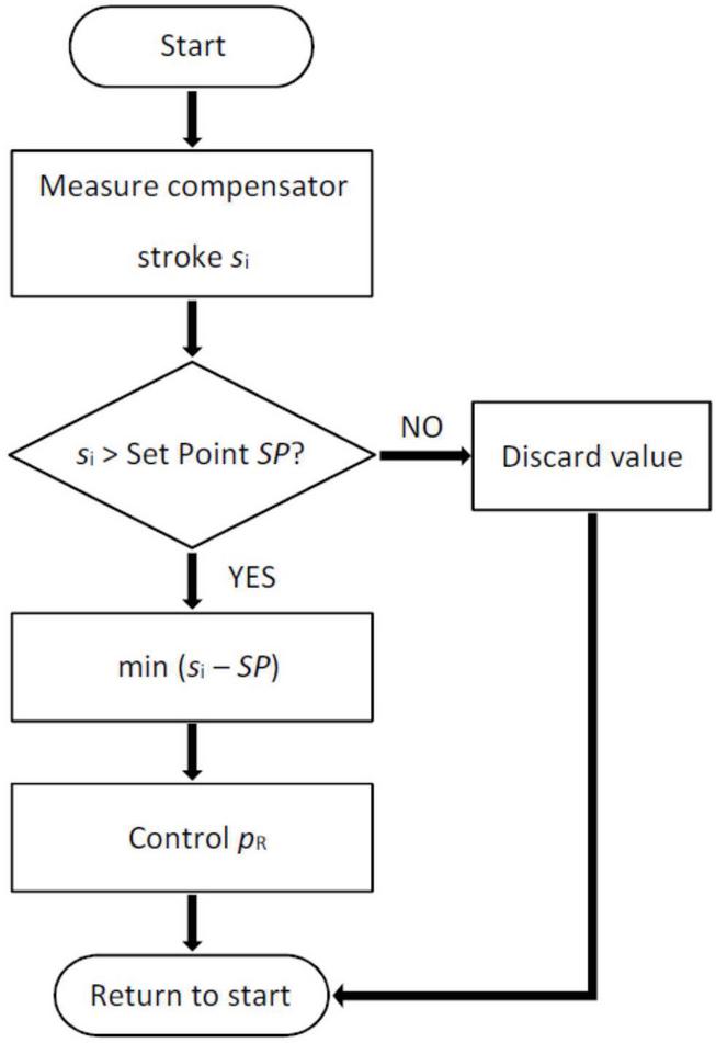
Figure 13 Control strategy.
Finally, the control strategy was validated via numerical model with the same test of paragraph 4.1, as seen in Figure 14, which displays the simulation results.
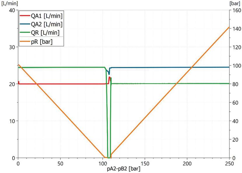
Figure 14 Simulation results of compensation test (resistant loads) with control system.
Section 1 is dominant up to 100 bar, therefore return flow QB2 is recovered in R; section 2 is dominant above 100 bar, therefore return flow QB1 is recovered in R. The flow QR is maximum, equal to the return flow, except when the two sections are at the same pressure, because here the recovery is not possible; p varies and it is equal to the two loads difference, confirming that the control system works properly. Comparing Figure 14 with Figure 8, it results that the control system allows recovering in all the range of the compensation by controlling p.
6 Estimation of Energy Saving and Recovery in a Digging Cycle of a Mini-Excavator
The Amesim model of the new DCV tuned in Chapter 4, together with the control strategy of pressure p defined in Chapter 5 was applied to a case study of the digging cycle of a mini-excavator 5-ton size. The objective is estimating the energy saving and recovery respect to a hydraulic system with a traditional load sensing flow-sharing DCV.
The applied cycle is proprietary and consists on digging, slewing, dumping and returning to the initial position. It involves the four functions of boom, arm, bucket and swing. To define the external loads to apply to the actuators and the stroke to give to the spools as a function of time, flows and pressures were measured and acquired during a digging cycle in a field test of a 5-ton mini-excavator with a traditional load sensing flow-sharing DCV.
Figures 15–18 show the flows and pressures implemented in the model of each actuator as a function of time.

Figure 15 Boom flows and pressures.
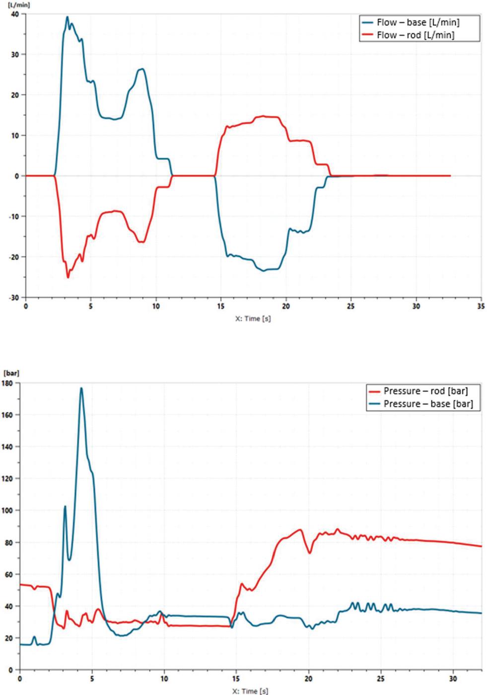
Figure 16 Arm flows and pressures.
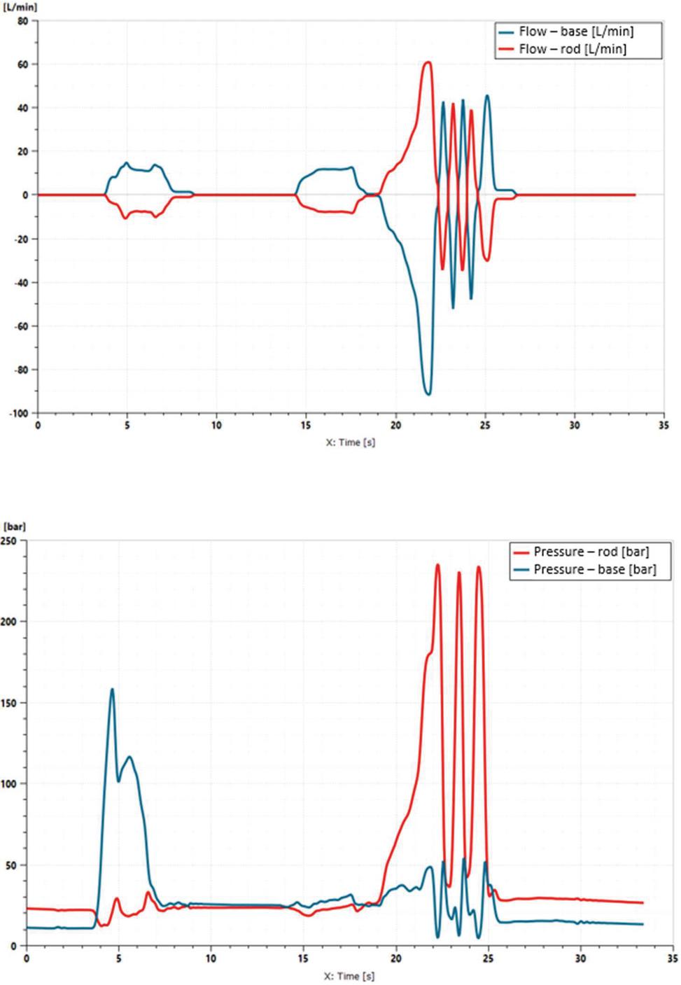
Figure 17 Bucket flows and pressures.
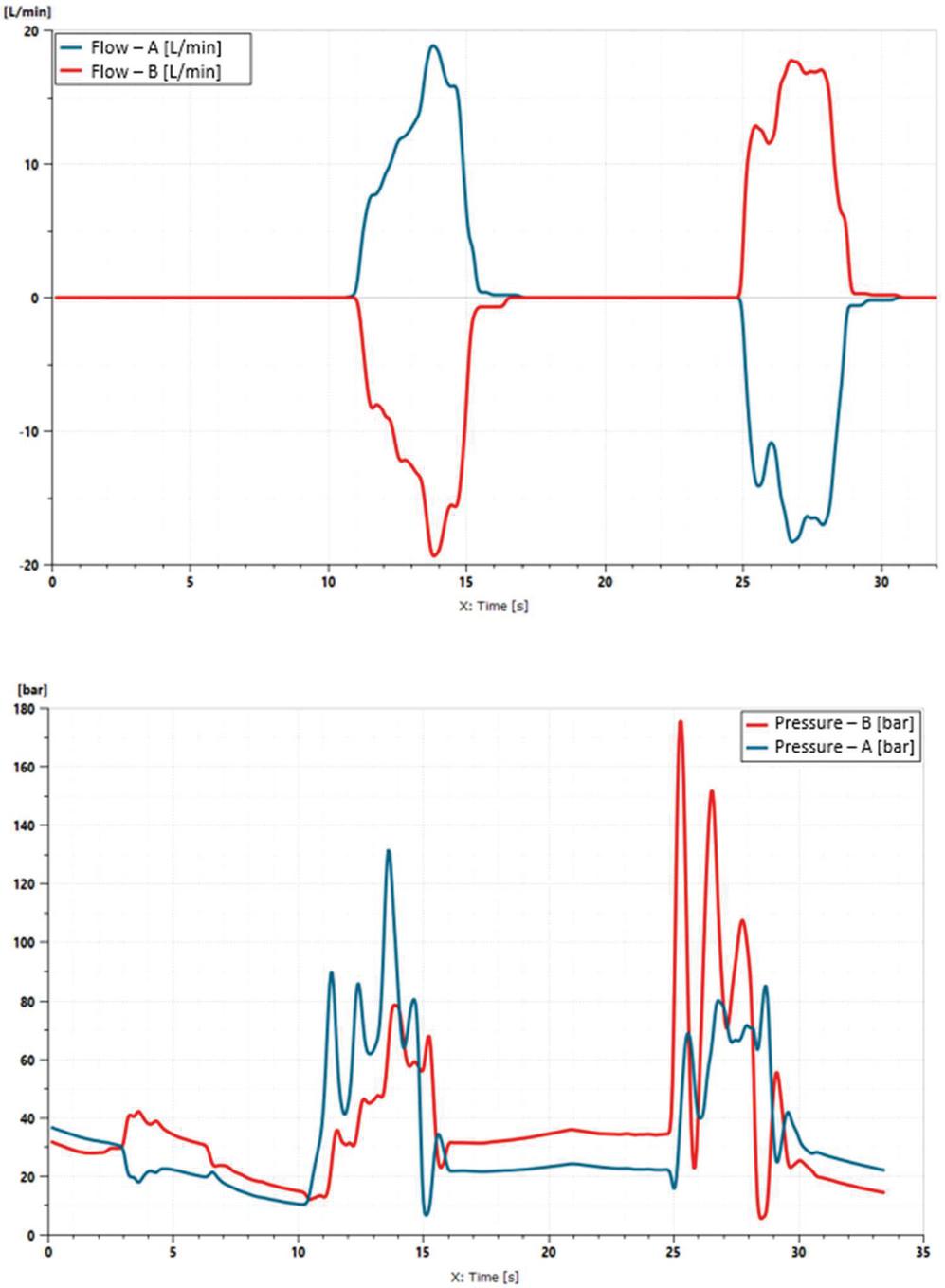
Figure 18 Swing flows and pressures.
Loads and spool strokes were derived from experimental data, knowing both the spool metering areas and the actuators geometry.
Figure 19 presents the model of the four sections new DCV and the implemented control strategy.

Figure 19 Amesim model of four sections and recovery control.
The results of the simulation are summarized in the energies balance during one cycle. Referring to the hydraulic system as a black box, there are two types of energies:
• Input energy: from the pump.
• Output energies: work (resistant minus overrunning loads), recoverable (hydraulic energy available in line R) and dissipated.
Input energy is equal to the sum of output energies.
Figure 20 compares the sum of output energies computed by the two numerical models. Since the cycle is the same, the two simulations perform the same work, which represent the proper function of the mini-excavator.
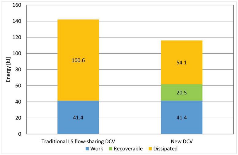
Figure 20 Energy output in a digging cycle.
The first outcome is that the new DCV allows a reduction of 18% of the pump energy, thanks to the fact that the spool meter-out notches are larger because compensator throttles only when necessary. The second outcome is that the recoverable energy is equal to 17% of the total energy input. Considering a battery driven vehicle, the new hydraulic system allows an overall 32% energy saving and recovery respect to the traditional DCV system, without considering generator, inverter and battery efficiency.
7 Future Developments
A more comprehensive control strategy is possible knowing the flows of each working section. This implies that the DCV has electro hydraulic commands for example.
To complete the recovery system, it is necessary to define how to use the recovered energy. This part of the hydraulic system, which has not been analysed in detail yet, depends on the application and on the decisions of the Original Equipment Manufacturer (OEM). At least the following options are possible:
1. Send the recovered flow directly into P line of the same hydraulic system (or another subsystem);
2. Like option nr.1, but with an accumulator and the components necessary to manage its charge/discharge;
3. Send the recovered flow to a variable displacement motor directly on main pump shaft;
4. Convert hydraulic into electric energy by means of hydraulic motor, electric generator, inverter and battery (see Figure 1).
Option nr.1 is similar to a regenerative system, with the advantage that recovered oil is available not only for one actuator but for all. Moreover, since there is no energy conversion, there is no loss due to it. On the other hand, if no other function is active during the recovery, recovered energy is lost, which is not optimal. Finally, in this option, the recovery superstructure is minimal; therefore, its extra cost is minimum.
In option nr.2, energy can be stored in the accumulator and used when possible [16, 20, 21]. On the other hand, the storage is limited due to the finite capacity of the accumulator and to its pressure setting, which does not allow recovering in all the conditions. Furthermore, the accumulator has its own efficiency. Finally, option nr.2 is more expensive because more components are required.
Option nr.3 allows assisting the ICE in driving the parasitic consumers such as alternator or cooling, if there is no other consumer active.
Option nr.4 is the most cost demanding and therefore the most difficult to apply, but considering that the market is requiring an increasing number of hybrid or full electric machines in which the battery is already present, if the recovery system allows downsizing the battery, it is possible that its cost turns to be worthwhile.
The focus of next activities will be on option nr.4, both to convert recovered oil enthalpy into electricity to be stored into batteries and to assist the motor that can compresses oil via the volumetric device. The motor/pump has to work in two quadrants at least and needs to be pressurized on both ports. It will be interesting to evaluate how much energy can be saved and how much recovered in a real case.
A collection of tests carried out on a lifting application, powered by an inverter controlled electric motor moving a reversible gear pump/motor, has been presented [22], see Figure 21. The energy regeneration during a complete cycle can save up to 42% of energy, considering an ideal battery, which is quite encouraging.
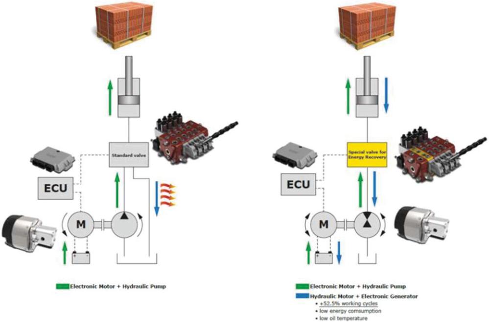
Figure 21 Simplified schematic of the recovery architecture: left OFF, right ON.
8 Summary and Conclusion
This article presents a new load sensing flow-sharing directional control valve with energy recovery capabilities. Each section has a three-way compensator downstream the spool meter-out to feed in a preferred way the recovery line R: this principle is at the basis of the recovery, which occurs in contemporary movements, in dependant sections at lower loads, and also in single movements with overrunning loads, thanks to a low pressure pilot source X feeding LS line. The downstream compensation brings also to energy saving, because it allows designing larger spool meter-out notches.
A prototype of the new DCV was built and tested on a bench. Test results confirmed the working principle and allowed tuning a lumped parameter model. The tests proved that the efficiency of the recovery is high in a quite large range of compensator stroke, suggesting a control strategy of pressure in recovery line R based on the monitoring of the local compensators position.
The DCV simulation model with the proposed control strategy was applied to a digging cycle, gathered experimentally from a mini-excavator 5-ton size. The simulation results show that: the hydraulic energy requested to the pump is 18% less compared to a traditional load sensing flow-sharing system; moreover, it is possible to recover in line R 17% of total input energy from pump.
Future work will involve the development of a recovery system on line R as in Figure 1, composed of a hydraulic motor M, a generator G and an inverter INV. In parallel, the DCV will be tested on a demo mini-excavator and other applications.
Acknowledgements
The authors thank Professor Paolo Casoli, Dipartimento Ingegneria Industriale at Università di Parma, Professor Andrea Vacca, Maha Fluid Power Faculty Chair at Purdue University, Professor Adolfo Senatore, Dipartimento Ingegneria Industriale at Università Federico II di Napoli, and Yi Huang, Walvoil R&D, for their contribution to the development of this project.
Nomenclature
| Variable | Description | Unit |
| A1, B1… | Work ports | [–] |
| A | Spool meter-in Area | [mm] |
| A | Spool meter-out Area | [mm] |
| A | Local compensator Area of way towards recovery line R | [mm] |
| A | Local compensator Area of way towards tank T | [mm] |
| DCV | Directional Control Valve | [–] |
| D | Line Downstream spool meter-in | [–] |
| D | Line Downstream spool meter-out | [–] |
| Pressure Difference p–p or pump margin | [bar] | |
| ECU | Electronic Control Unit | [–] |
| G | AC Generator | [–] |
| ICE | Internal Combustion Engine | [–] |
| INV | Inverter AC-DC | [–] |
| LS | Load Sensing, highest pressure among working sections | [–] |
| M | Hydraulic Motor | [–] |
| MRV | Main Relief Valve | [–] |
| p, p | Work port A, B pressure | [bar] |
| Load Sensing pressure | [bar] | |
| Pump pressure | [bar] | |
| Pressure in recovery line R | [bar] | |
| P | Variable Load Sensing Pump | [–] |
| PRV | Pressure Reducing Valve | [–] |
| PS | Position Sensor | [–] |
| Q, Q | Work port flow, or meter-in flow | [l/min] |
| Q | Flow from the actuator, or meter-out flow | [l/min] |
| R | Energy Recovery line | [–] |
| s | Compensator stroke | [mm] |
| SP | Compensator stroke set point | [mm] |
| X | Pilot line fed by the Pressure Reducing Valve | [–] |
| T | Tank | [–] |
| R | Efficiency of compensator recovery | [adim] |
References
[1] Municipality of Amsterdam, Clean Air Action Plan, Amsterdam, The Netherlands, 2019.
[2] Lajunen, A., Sainio, P., Laurila, L., Pippuri-Mäkeläinen, J., Tammi, K. Overview of Powertrain Electrification and Future Scenarios for Non-Road Mobile Machinery, In: Energies, 2018.
[3] Boggia, P., Global Off-Highway vehicle electrification trends: forecast to 2030, In: IVT Expo Virtual Conference, 2021.
[4] Volvo CE, Prototype Electric Excavator, https://www.volvoce.com/global/en/this-is-volvo-ce/what-we-believe-in/innovation/prototype-electric-excavator/, visited on October 26th, 2021.
[5] Weber, J., Beck, B., Fischer, E., Ivantysyn, R., Kolks, G., Kunkis, M., Lohse, H., Lübbert, J., Michel, S., Schneider, M., Shabi, L., Sitte, A., Weber, J., Novel system architectures by individual drives, In: 10th International Fluid Power Conference, Dresden, Germany, 2016.
[6] Lodewyks, J., Zurbrügg, P., Decentralized energy-saving hydraulic concepts for mobile working machines, In: 10th International Fluid Power Conference, Dresden, Germany, 2016.
[7] Minav, T., Bonato, C., Sainio, P., Pietola, M., Direct Driven Hydraulic Drive, In: 9th International Fluid Power Conference, Aachen, 2014.
[8] Pellegri, M., Green, M., Macpherson, J., McKay, C., Caldwell, N., Applying a Multi-Service Digital Displacement§Pump to an Excavator to Reduce Valve Losses, In: 12th International Fluid Power Conference, Dresden, Germany, 2020.
[9] Michel, S., Weber, J., Prediction of the thermo-energetic behaviour of an electrohydraulic compact drive, In: 10th International Fluid Power Conference, Dresden, Germany, 2016.
[10] Michel, S., Weber, J., Investigation of self-contamination of electrohydraulic compact drives, In: 10th JFPS International Symposium on Fluid Power, Fukuoka, Japan, 2017.
[11] Sitte, A., Beck, B., Weber, J., Design of independent metering control systems, In: 9th International Fluid Power Conference, Aachen, 2014.
[12] Linjama, M., Digital fluid power – state of the art, In: 12th Scandinavian International Conference on Fluid Power, Tampere, Finland, 2011.
[13] Marani, P., Milani, M., Mesturini, D., Busani, U., Experimental Evaluation of the New Meter Out Sensing Architecture, In: 11th International Fluid Power Conference, Aachen, Germany, 2018.
[14] Siebert, J., Geimer, M., Reduction of System Inherent Pressure Losses at Pressure Compensators of Hydraulic Load Sensing Systems, In: 10th International Fluid Power Conference, Dresden, Germany, 2016.
[15] Mesturini, D., Dolcin, C., Busani, U., Marani, P., Bonavolontà, A., Frosina, E., Optimisation of directional control valves through downstream compensation approach, In: 12th International Fluid Power Conference, Dresden, Germany, 2020.
[16] Casoli, P., Riccò, L., Campanini, F., Dolcin, C., Lettini, A., Hydraulic Hybrid Excavator: Layout Definition, Experimental Activity, Mathematical Model Validation and Fuel Consumption Evaluation, In: 10th International Fluid Power Conference, Dresden, Germany, 2016.
[17] Walvoil SpA, ALS Adaptive Load Sensing, http://www.walvoil.com/products/valves-for-special-applications/als-2, visited on October 26th, 2021.
[18] Lenzgeiger, U., Maier, U., Schmuttermair, P., Electronic Load-Sensing for Tractors, In: 11th International Fluid Power Conference, Aachen, Germany, 2018.
[19] Fu, S., Li, Z., Lin, T., Chen, Q., Ren, H., A Positive Flow Control System for Electric Excavators Based on Variable Speed Control, In: Appl. Sci. 2020, 10, 4826.
[20] R. Peña O. and J. Leamy M., An efficient architecture for energy recovery in hydraulic elevators, In: International Journal of Fluid Power, 2015 Vol. 16 Iss 2.
[21] A. Bedotti, F. Campanini, M. Pastori, L. Ricco, P. Casoli, Energy saving solutions for a hydraulic excavator, In: Energy Procedia 126 (2017), pp. 1099–1106.
[22] Morselli S., Marani P., Dolcin C., Ferrari C, Efficiency analysis of an electro-hydraulic drive for mobile lifting machines, In: Proceedings of Bath/ASME Symposium on Fluid Power and Motion Control 2020.
Biographies

Gianluca Ganassi received his master’s degree in Mechanical Engineering from University of Parma in 2001. He has been working for more than 20 years in R&D department of Walvoil (member of Interpump Group), where he is currently a Team Manager. He published several works, patents and participated to conferences. His projects are mainly related to load sensing flow sharing directional control valves for off-road vehicles, especially earth moving and material handling. His research is currently about energy recovery directional control valves for mobile applications.

Davide Mesturini has been Research & Development Manager at Walvoil, Interpump Group, since 2015. Graduated in Mechanical Engineering at Politecnico di Torino in 1998 and specialized in Hydraulics, he obtained a Master in Technology & Innovation Management at Bologna Business School. Since 1999 he has been working in the hydraulic field as Project Leader, Application Engineer and Technical Manager, focusing in particular on Directional Control Valves. He has published several works and participated in several conferences; he has acquired various patents and recently received an international award for hydraulic innovation. Today he carries out research mainly on efficient and sustainable solutions for the mobile machinery hydraulic.

Cesare Dolcin received his M.S. Degree in Mechanical Engineering from University of Bologna in 1996; after being appointed Army’s Officer by SACA of Sabaudia in 1997 and getting a post-degree in Space System from University of Padua in 1998, he took a B.S. in Physics from University of Modena in 2011. After working seven years in the field of components for alternative fuels and low emission vehicles, in 2005 he joined Walvoil (now member of Interpump Group) as Test Department Manager. His research activities regard fluid power components application to off-highway mobile machines, mainly involving aspects of energy management (saving and recovery) and metal fatigue behaviour.

Antonella Bonavolontá is a mechanical engineer working on the study and optimization of valves in the fluid power field. From 2018 to 2021, she was involved in Fluid Power Research, getting her industrial Ph.D. at the University of Naples Federico II in collaboration with the company Walvoil Interpump Group, in 2022. She is author of several papers and she took part in many international conferences. Working in both academic and industrial sectors, her research interest is in the design optimization of valves by means of numerical modeling and in prototype development and testing.

Emma Frosina is an Assistant Professor at the Department of Engineering of the University of Sannio Benevento. She received her M.S. Degree in Mechanical Engineering from the University of Naples Federico II in 2012 and her Ph.D. Degree in Mechanical Systems Engineering in 2016. She is the author of over 50 scientific papers published in peer-reviewed international journals and in international conference proceedings. Her research interests are in the fluid power field where she is mainly specialized in modeling and optimization of components (machines, valves, etc.) using numerical approaches (both lumped parameter and three-dimensional CFD) and testing.

Pietro Marani is researcher at CNR-STEMS (Institute of Science and Technology for Energy and Mobile Sustainability of the National Research Council of Italy), formerly IMAMOTER. Received his Ph.D. in Mechanical Engineering from Modena and Reggio Emilia University. Author of several papers and of two patents, his main research interests are energy saving architectures for mobile machines, lumped parameter simulation and innovative sensors.
International Journal of Fluid Power, Vol. 24_2, 361–392.
doi: 10.13052/ijfp1439-9776.2428
© 2023 River Publishers