Experimental Verification of An Electro-Hydraulic Actuation System Driven by An Integrated Electro-Hydraulic Unit
Shaoyang Qu1,*, Federico Zappaterra1, Andrea Vacca1, Zifan Liu2 and Enrique Busquets2
1Maha Fluid Power Research Center, Purdue University, Indiana, USA
2Bosch Rexroth, South Carolina, USA
E-mail: shaoyang.qu@bosch.com
*Corresponding Author
Received 27 September 2022; Accepted 12 January 2023; Publication 29 April 2023
Abstract
This paper proposes an electro-hydraulic actuator (EHA) system, and a novel-designed electro-hydraulic unit (EHU) consisting of a fixed-displacement hydraulic gear machine and a variable-speed electric machine. The novel EHU design integrates an electric machine and a hydraulic machine in a single housing, targeting optimal compactness, power density, and component reduction. The EHA system features an open circuit design, where hydraulic hoses connect the EHU with a tank, a valve manifold, and the hydraulic cylinder. In this way, the proposed EHA technology can be used to implement distributed hydraulic actuation in a vehicle without requiring changes to the hydraulic actuators or at the overall layout of the hydraulic components with respect to the original vehicle design. A dedicated test rig is developed to verify the performance of the proposed EHA system. The efficiency of the EHA is measured in a steady state and under a realistic duty cycle of a commercial compact loader. The efficiency of the EHA system based on the measurements on the test rig can reach 54% with up to 20 kN load and 6 kW power level. Furthermore, the EHU is implemented on the reference machine to drive the boom function. Preliminary results on the performance of the EHU show an efficiency of up to 68% under different loading conditions.
Keywords: Electro-hydraulic actuator, electro-hydraulic unit, throttle-less actuation, mobile hydraulics, energy recuperation, four-quadrant linear actuator.
1 Introduction
The recent electrification trend affecting off-road vehicles is providing a push towards dedicated electrified hydraulic actuation systems. Although in many cases traditional centralized fluid power architectures are still used in electric vehicles, there is an increasing interest for electro-hydraulic actuator (EHA) solutions that can avoid throttling losses. EHAs enable energy recuperation during overrunning loads and have in general higher transmission efficiency, thus reducing energy consumption, which is important to meet regulations in emissions or to increase battery autonomy in the case of electric vehicles. A compact and self-contained EHA is one of the most attractive solutions, which was first adopted in aviation control [1–4], (e.g., flight actuation, landing gear, seat adjustment). In recent years, the self-contained EHA attracts the attention of industrial applications [5, 6], and mobile hydraulics [7, 8]. However, particularly for mobile applications, self-contained EHAs are still at the research stage, due to the cost and other technical challenges, such as providing sufficient cooling.
Figure 1 depicts a modular view of a self-contained EHA based on a commercial product, for industrial applications [9]. The EHA integrates the entire fluid power system, with a well recognizable layout for the components, i.e., the actuator, the valves, the reservoir-accumulator, and the power drive. This kind of EHA is a popular solution due to the modularity and the reduced chance of leakages. Nevertheless, the adoption of self-contained EHAs in off-road vehicles is challenged by the cost and space requirement, which in many cases requires modification of the mechanical structures. The thermal behavior of the self-contained EHA could be another concern based on some previous studies [10, 11].
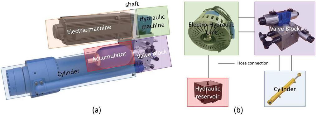
Figure 1 Comparison of the classical EHA configuration and the proposed EHA system. (a) Classical self-contained EHA. (b) Proposed EHA configuration, flexible to be implemented on mobile applications.
This paper, instead, focuses on the performance of the hydraulic system in combination with the EHU. The hydraulic system under study in this work builds upon previous work on a four-quadrant EHA developed by the authors [12–14]. In previous studies, the energy performance was studied in terms of the four-quadrant EHA using commercial drives [15]. The thermal analysis of the proposed EHA system was also conducted, aiming to predict the steady-state temperature under intense duty cycles [16]. Figure 2 shows the four-quadrant operation in terms of load force and actuation velocity. Taking a compact loader as a reference machine, the four-quadrant operation corresponds to the boom raising/lowering and tilting bucket up/down.
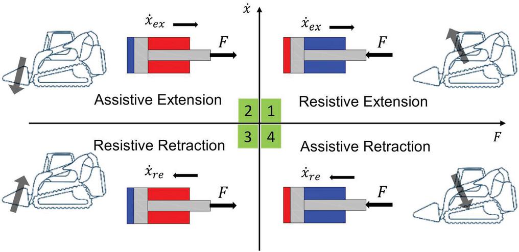
Figure 2 Four-quadrant operation in terms of load force and actuation velocity.
The EHU is specifically designed to drive the actuators. The design integrates a hydraulic machine (HM) coupled with a permanent magnet type electric machine (EM) without any external shaft. The unit, which is described in [17, 18], and [19], uses an external gear type hydraulic machine with a maximum power of 15 kW. This unit is air-cooled using fans mounted on the rotor of the electric machine. The unit is exceptionally power dense and is conceived to achieve component reduction, ease the manufacturability and the parts assembly. Regarding the dimensions, the EHU measures 230 mm in diameter with an axial length of 175 mm.
This study focuses on the testing and validation of the EHU as well as on the energy performance of the EHA considering four-quadrant operation. Both resistive loading conditions and assistive loading conditions (i.e., energy recuperation) are investigated, and the efficiencies in the steady state are analyzed. The experimental verification of the proposed EHA system is performed in two phases. First the system is tested on a dedicated test rig using a realistic duty cycle in terms of four-quadrant operation. Then, the proposed system is implemented on the compact loader (shown in Figure 3) to actuate the boom function for preliminary demonstration. The two-phase tests validate the performance of both the EHA system and the novel designed EHU towards the electrified mobile hydraulic applications.
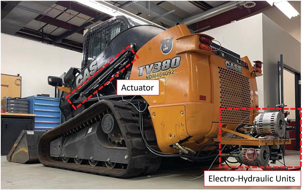
Figure 3 Electro-hydraulic units mounted on the reference machine and connected to the actuators.
The paper is structured in the following order: Section 2 introduces the EHA system configuration. Section 3 describes the dedicated test rig to verify the performance of the EHA. Section 4 shows the experimental results and outlines the energy performance of the proposed system and novel EHU. Section 5 concludes the work with final remarks.
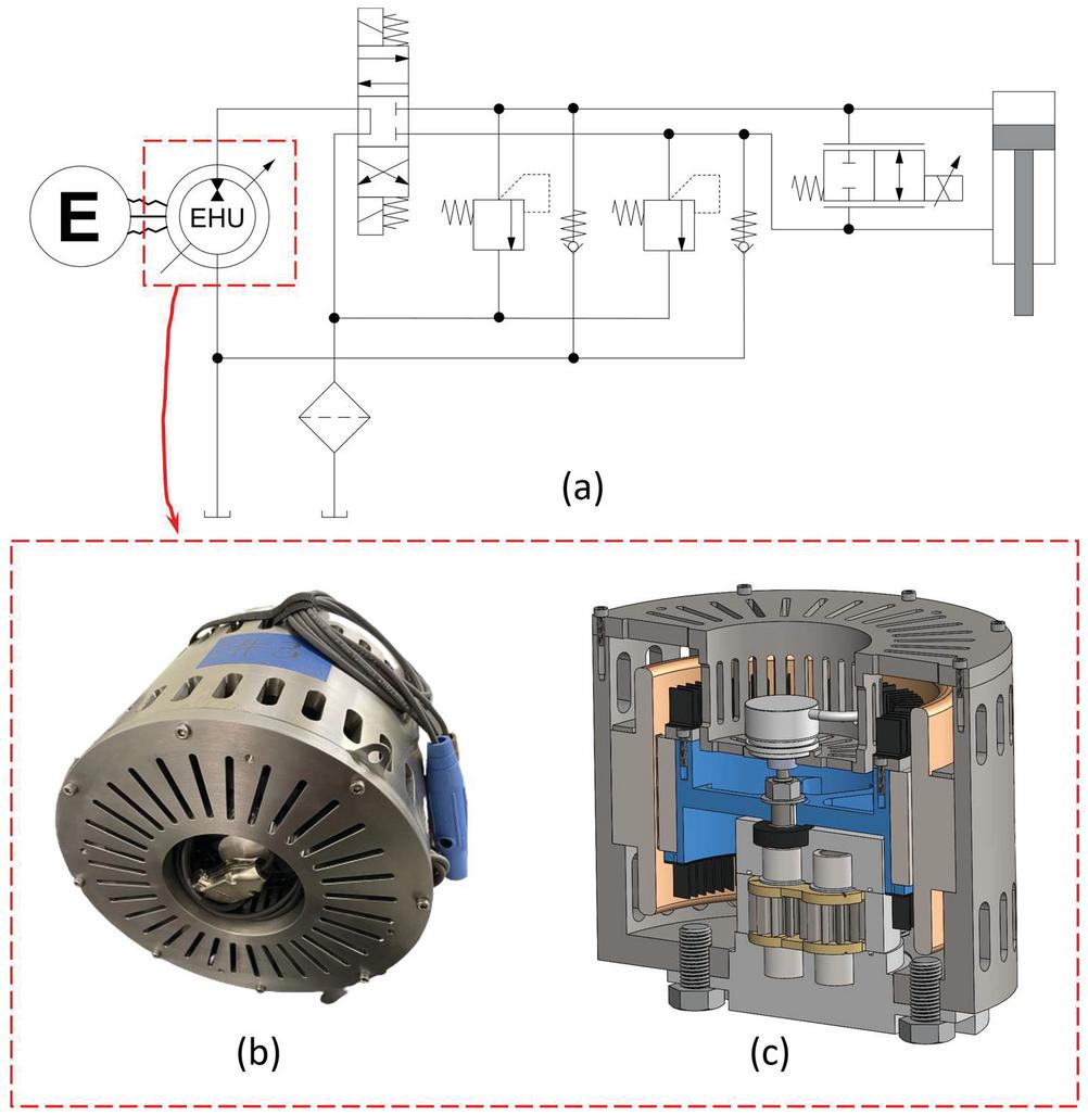
Figure 4 Configuration of the proposed EHA system. (a) Schematic of the hydraulic system. (b) Picture of the EHU prototype. (c) Cross-section to show the EHU inner structure.
2 Proposed System
Figure 4 shows the open-circuit ISO schematic and significant images of the novel EHU implemented in the EHA. The EHA design adopts an open circuit system, in which the EHU is operated in two quadrants in terms of speed and pressure, and one port of the EHU is always connected to the hydraulic tank. By switching position of the 4/3 directional valve, the circuit can achieve four-quadrant actuation and allows energy recuperation under overrunning load conditions. The bypass valve parallel to the cylinder plays a key role in the design. When low-speed actuation is required, the bypass valve can recycle flow to regulate the actuation velocity without relying on the action of the hydraulic machine. In other words, using hydraulic machines with minimum speed limit (e.g., fixed-displacement pump) does not impact velocity range of the cylinder. The role of the by-pass valve comes into play also during fast assistive phases of the duty cycle of the vehicle. During the assistive phases the recuperation of energy using the EHU as a generator is possible. However, during a fast actuation, the flow rate generated may be excessive compared to what the EHU can process, therefore, the by-pass valve can redirect part of the flow rate to tank. This strategy allows to not oversize the EHU and strongly mitigates the constraints on the maximum velocity of the actuators.
In general, the bypass valve gives more flexibility to the type and size of the EHU with a given operation request. More details on the working principles of the hydraulic circuit can be found in Refs. [13, 14].
The EHU consists of an external gear type hydraulic machine integrated into the rotor inner space of a permanent magnets synchronous electric machine. In Figures 4(b) and 4(c) can be seen respectively the EHU prototype and a cross section of its 3D model. As can be seen from the image, contrary to the conventional configuration of the electric motor and the hydraulic pump, where the two machines are connected axially by a shaft, the proposed EHU design places the hydraulic machine inside the rotor of the electric machine (radial arrangement). This sort of implementation takes advantage of the power to weight difference of two machines. Moreover, electric machines with a wider radius can generate more torque with the same amount of conductor material. Therefore, the radial arrangement can reduce conductor material for the same power rating. The space inside the rotor inner radius is used to position the hydraulic machine. A comparison of the traditional and proposed design is illustrated in Figure 5.
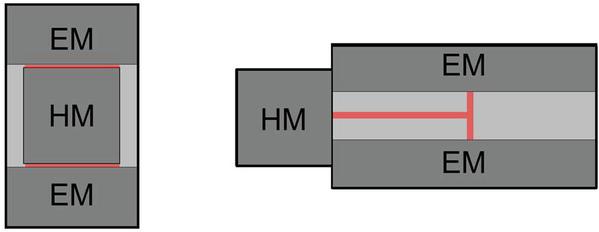
Figure 5 Proposed EHU configuration (left). Traditional EHU configuration (right). In the image is also highlighted in red the connecting element.
The EHU also integrates an air-cooling system for the electric motor, which consists in radial fans fixed with the rotating assembly. The EHU symbol varies from conventional ones to highlight the shaftless structure, which integrates the hydraulic machine inside the electric machine. The EHU is powered by an external electric supply and simplified as the symbol with capital E.
The hydraulic and the electric machine are optimized with respect to the operating conditions reported in Table 1. OC1 and OC3 represent the raising and lowering phase of the nominal duty cycle of the reference machine. OC2 represents the maximum power operating condition requested by the reference machine.
Table 1 Operating conditions targeted by the optimization process
| Flowrate | Differential Pressure | Hydraulic Power | |
| OC1 | 45 L/min | 120 bar | 09.0 kW |
| OC2 | 45 L/min | 210 bar | 15.8 kW |
| OC3 | 70 L/min | 032 bar | 03.7 kW |
The HM and EM of the EHU are designed based on an optimization procedure that utilizes a lumped parameter model dedicated to the HM and one dedicated to the EM. The coupled simulation of the two machines is crucial in understanding the optimal velocity of the EHU. The rotation velocity must be carefully selected to ensure the maximum efficiency of the electric machine and the proper functionality of the hydraulic machine. For the same value of output power, an electric machine rotating at higher velocity requires less current, therefore it produces less resistive losses in the windings. These losses are the highest component of inefficiency for EM applications. However, hydraulic machines rotating at higher velocity can develop incomplete filling issues and considerable mechanical losses in the lubricated interfaces. For the hydraulic machine the fluid dynamic model described in [20] and [21] was used. The electric machine model is described in [22].
2.1 Objective Functions
The optimization targets four objective functions. As shown in Equation (1), the first objective function aims to minimize the power consumption of the EHU on the nominal duty cycle of the reference machine. In Equation (1), and are the power requested by the HM in the raising phase and lowering phase, and are the efficiencies of the EM in motoring and generating mode, and is the ratio between raising time and lowering time in typical cycle.
| (1) |
The second and third objective function of the optimization aim to minimize the torque ripple and flow ripple signals A-weighted power generated by the EHU. In Equations (2) and (3), and are the power level of the flowrate and torque signals, is the A-weighting function, and and are the Fourier transformed flowrate and torque signals.
| (2) | ||
| (3) |
As shown in Equation (4), the fourth objective function aims to maximize the power density of the unit, calculated as the maximum output power over the total volume of the EHU. Equation (5) shows the total volume calculation.
| (4) | |
| (5) |
2.2 Constraints
The optimization set up and the generation of feasible HM and EM designs requires several constraints, however, for brevity will be listed only the one most important from a EHU functionality perspective.
First, as shown in Equation (6), the pressure peak in the HM meshing zone is constrained. To avoid localized cavitation phenomena raising after the meshing zone, Equation (7) is posed to constraint the cavitation area. The cavitation area is the area bounded by the tooth space volume pressure and the saturation pressure when the tooth space volume pressure is below the saturation pressure. This simple and very inexpensive calculation, shown in (8), suit very well the optimization context and help the designer to exclude the designs that would tend to produce localized cavitation.
| (6) | |
| (7) | |
| (8) |
Finally, all the EHU presenting an efficiency below a determined limit are discarded.
| (9) |
2.3 Results
The optimization process evaluated more than 3000 designs, among which the one for this study was selected for best overall performance.
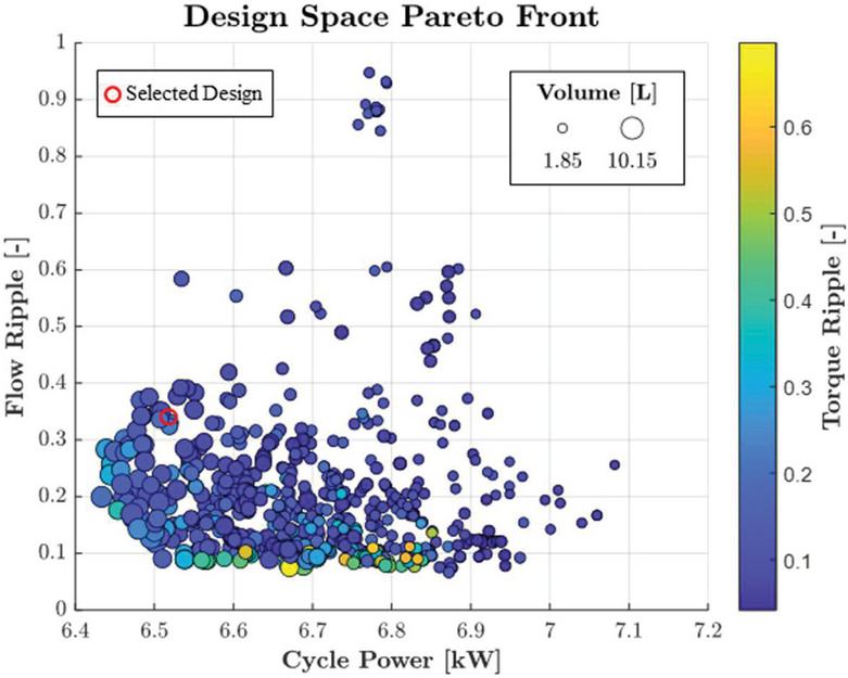
Figure 6 Pareto front reporting the optimized designs and highlighting their performance with respect to the objective functions.
From the pareto front shown in Figure 6 a design was selected with the characteristics reported in Table 2.
Table 2 Selected EHU EM and HM parameters
| Electro-Hydraulic Unit | ||
| Cycle power | 6.52 | kW |
| Flow ripple | 0.33 | – |
| Torque ripple | 0.21 | – |
| Volume | 5.74 | L |
| EM Parameters | ||
| Rotor lamination material | M15 | |
| Stator lamination material | M15 | |
| Permanent magnets material | SM2Co17-R30S | |
| Conductor material | Copper | |
| Pole pairs | 5 | – |
| Depth inertia region | 60 | mm |
| Depth of rotor backiron | 7.53 | mm |
| Magnets depth | 3.02 | mm |
| Air gap | 1.50 | mm |
| Depth of tooth base | 12.57 | mm |
| Tooth fraction | 0.55 | – |
| Depth of stator back iron | 7.83 | mm |
| Permanent magnets fraction | 0.7 | – |
| Active length | 61.08 | mm |
| Peak fond. Conductor density | 39.75 | cond/rad |
| Coeff. of 3rd harmonic conductor density | 0.34 | – |
| Current density | 2.76 | A/mm |
| Hydraulic Machine | ||
| No. of teeth | 12 | – |
| Theoretical displacement | 10.69 | cc/rev |
| Module | 2.35 | – |
| Addendum | 3.15 | mm |
| Dedendum | 4.14 | mm |
| Drive pressure angle | 14.9 | |
| Coast pressure angle | 10.84 | |
| Drive root radius of curvature | 0.005 | mm |
| Coast root radius of curvature | 0.329 | mm |
| Profile correction | 0.31 | – |
| Gear width | 20.11 | mm |
| Nominal interaxis | 30.69 | mm |
| Helix angle | 0 | |
| Journal bearing shaft length | 8.03 | mm |
| Journal bearing shaft diameter | 10.71 | mm |
| Journal bearing nominal radial clearance | 0.02 | mm |
After having determined the EM morphology and the gear set profile, the axial balancing system design is refined using the model that was first described in [23], and then perfectioned with the addition of the fluid-structure interaction [24]. The whole axial balance system design procedure and the outcome of the design effort is described in [25]. In the design process, great effort is put in the EHU size and component reduction. These aspects are of paramount importance and aim to ease as much as possible the integration of this technology in commercial OEM vehicles and mitigate the cost of the additional components needed to adopt this technology. The details of the EHU inner structure are provided in Figure 7.
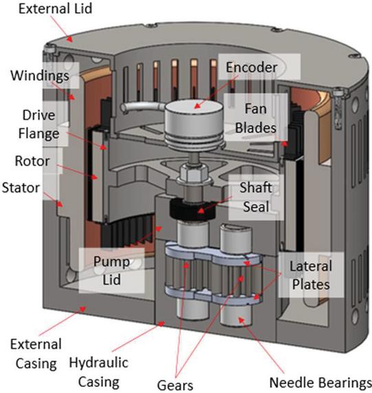
Figure 7 3D model cross sectional view highlighting the internal components of the EHU.
The EHU is enclosed by a cylindrical external casing on the inside of which is press fit the electric machine stator. On one side of the cylinder can be found the opening in which the hydraulic machine is inserted. To ease the connection of the hydraulic machine with the hydraulic lines, its ports extend in the axial direction and the openings are located on the external flange that must be bolted to the external casing to hold the hydraulic machine in place. The hydraulic machine is designed so that the drive gear shaft can be positioned in the centre of the stator and can hold the drive flange that connects it to the electric machine rotor. To reduce the number of components and maximize the compactness the electric machine rotor is press fit on the drive flange. The hydraulic machine casing is sized so that it can fit inside the drive flange allowing the hydraulic machine to take advantage of the electric machine core space which would be otherwise unused. This procedure not only reduce the axial length of the whole unit but remove the necessity of bearing elements for the electric machine, expensive location features needed to proper align hydraulic and electric machine, and complex coupling elements. To provide proper cooling to the electric machine, centrifugal fans are attached on both sides of the drive flange. These, in combination with the openings machined in the external casing and lid, provide air to the electric machine windings.
An encoder is positioned on the outside of the external casing lid. The encoder provides the position feedback for control purpose of the EM. More details on the EHU and its morphology can be found in [17] and [18].
As shown in Figure 8, the EHU can be assembled and disassembled in macro components like the hydraulic machine and the rotating assembly, facilitating its maintenance.
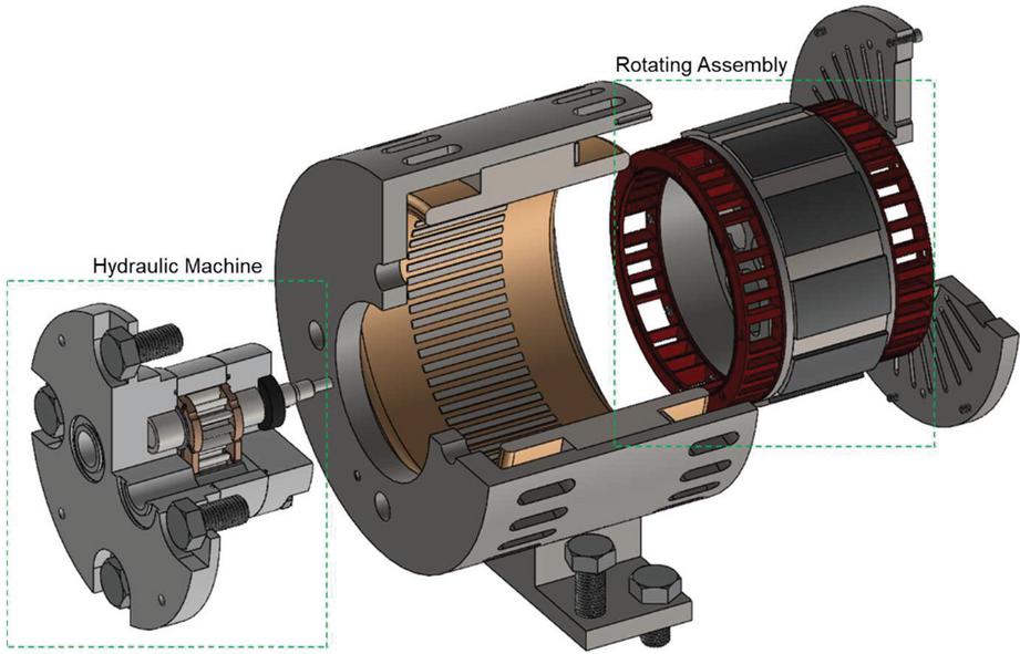
Figure 8 EHU highlight of the macro components. When the macro components are assembled, the hydraulic machine must be positioned first, and then the rotating assembly.
3 Experimental Setup
The EHA system is verified on the test rig with a loading force being actively controlled. Such set up allows repeatable and accurate results before the direct testing on an actual vehicle. Figure 9 shows a picture of the dedicated experimental setup for the proposed EHA, located at the Maha Fluid Power Research Center of Purdue University. The main mechanical structure of the test rig is made of two equal cylinders: an EHA drive and a load drive. The cylinders are the same of a chosen reference vehicle, the Case TV 380 compact loader as shown in Figure 3. In this way the experiments conducted on the test rig can reflect realistic duty cycles. The load drive has a hydraulic circuit that can pressurize the cylinder chamber so that both resistive and assistive load conditions on the EHA can be established. The loading force is controlled by two proportional reducing-relieving valves. The locations of the EHU, the manifold, the cylinder, and the tank are highlighted in Figure 9. The EHU is controlled by a stationary inverter device, which will be described in the following paragraphs.
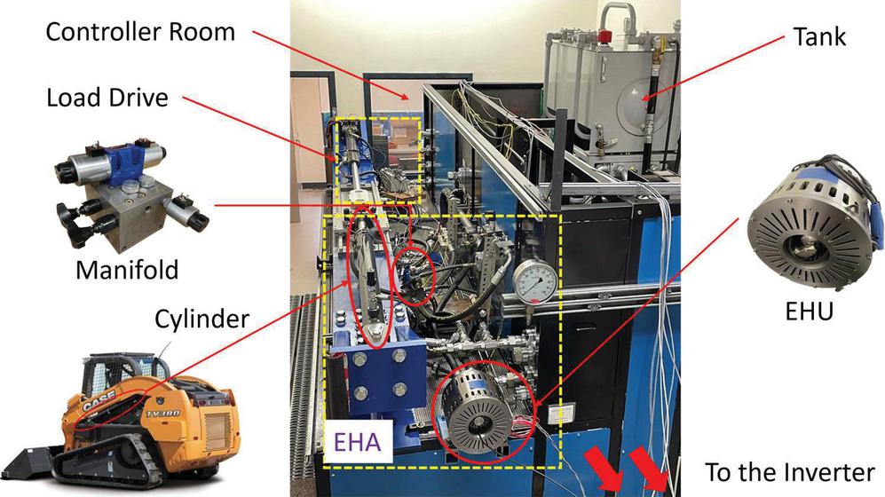
Figure 9 Dedicated experimental setup of the proposed EHA system in Maha Fluid Power Research Center.
Table 3 summarizes the parameters of the reference application, which is the boom cylinder used on a compact loader, as shown in Figure 9. The sizing methods are detailed in previous works of the authors as [14] and [15]. The maximum load force generates a pressure of 120 bar, while the system components are selected for extreme conditions up to 210 bar (e.g., relief valve), and the continuum pressure of the EHU is up to 120 bar.
Table 3 Parameters of the actuation duty cycle
| Actuation Parameters | Value [Unit] | |
| Cylinder size | Length of stroke | 0.8865 [m] |
| Diameter of piston | 69.9 [mm] | |
| Diameter of rod | 44.2 [mm] | |
| Cycle time | Extension time | 4.43 [s] |
| Retraction time | 2.63 [s] | |
| Loading condition | Maximum pressure | 120 [bar] |
Table 4 gives the main parameters of the components used in the proposed system, such as the size and operating conditions of the hydraulic machine and electric machine.
Table 4 Main parameters of the components
| Parameters of Components | Value [Unit] | ||
| EHU | Hydraulic pump | Nominal displacement | 10.69 [cc/rev] |
| Maximum speed | 4300 [rpm] | ||
| Minimum speed | 500 [rpm] | ||
| Electric machine | Nominal speed | 4300 [rpm] | |
| Nominal torque | 20.87 [Nm] | ||
| Nominal current | 24.22 [A] | ||
| Number of poles | 10 [–] | ||
| Valve | Check valve | Cracking pressure | 0.5 [bar] |
| Relief valve | Relief pressure | 210 [bar] | |
| Reservoir | Tank pressure | atmospheric | |
Table 5 lists the product number of the main hydraulic components on the test rig. The hydraulic valves are selected to fulfill the actuation requirements given in Table 1.
Table 5 Hydraulic component list of the EHA test rig
| Component | Product Number |
| 4/3 Directional valve | Rexroth 4WE10G5X/EG24N9K4/M |
| Prop. 2/2 directional valve | Rexroth KKDSR1NB/HCG24N0K4V |
| Check valve | Rexroth 043120005603000 |
| Relief valve | Rexroth DBDH6G40012 |
| Filter | Rexroth 50LEN0063-H6XLA00-V5,0-M-R3 |
Figure 10 shows the setup of the power electronics. There are two inputs of this device: one with 120VAC which is further rectified to 24VDC for the low-voltage control section, the other with 3-phase high voltage (440VAC) to drive the electric machine. The power flow from the power source to the electric machine is indicated with red arrows. The inverter with the control section regulates the input voltage, so that the permanent magnet electric machine can be controlled properly. The ice-cube relays and contactor coils ensure the safety under high-voltage operation. The filters eliminate the noise from the raw input power: the mains filter is for the mains power from the source to the inverter, and the motor filter is for the power flow from inverter to the electric machine. The braking resistor works to dissipate the energy from overrunning load. This is needed due to the absence of an energy storage device (e.g., battery) in this experimental set-up. When implemented in the reference machine, the system will use a battery to recuperate energy from overrunning load (e.g., lowering the boom).
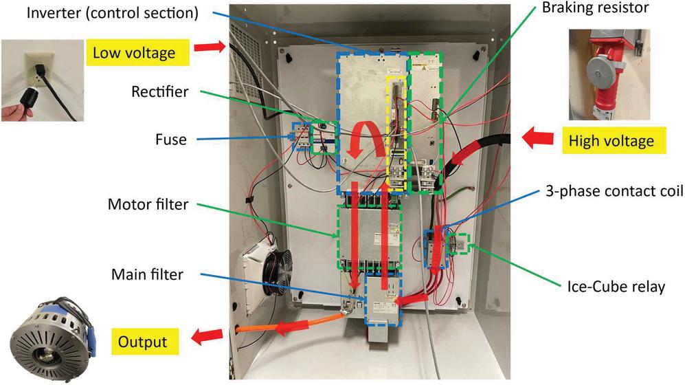
Figure 10 Power electronics setup to drive the EHA system.
The control section of the inverter (highlighted in yellow block in Figure 10) has local IOs to communicate with the main controller developed in Compact RIO controller (CRIO), including analog and digital input/output. Thus, the speed command of the EHU can be given via analog joystick signals, and safety can be ensured by connecting E-stop button to the digital ports.
Table 6 lists the electrical component list of the inverter setup.
Table 6 Electrical component list of the inverter setup
| Component | Product Number |
| Inverter | Rexroth HCS03.1E-W0100-A-05-NNNN |
| Control Section | Rexroth CSH02.1B-ET-EC-EC-NN-NN-NN-FW |
| Firmware | Rexroth FWA-INDRV*-MPC-21VRS-D5-1-NNN-NN |
| Mains filter | Rexroth HNK01.1A-A075-E0080-A-500-NNNN |
| Motor filter | Rexroth HMF01.1A-N0K2-D0073-A-500-NNNN |
| Braking resistor | Rexroth HLB01.1D-02K0-N03R4-A-007-NNNN |
As an overview, Figure 11 gives a conceptual schematic of the overall experimental setup, (the mechanical structure shown in Figure 9, and the inverter setup shown in Figure 10). The data acquisition system is also included in Figure 11: a joystick as the operator input, CRIO as the central processor and controller, and a laptop to monitor the status of the test rig and for data post-processing. The main sensors (e.g., position sensor, pressure sensors, encoder, etc.) are given this schematic as well. As now the inverter device is stationary and for industrial usage, the power is not from DC bus, but 3-phase AC sources. For the implementation a battery (i.e., DC power) will be utilized as the power source. For convenience, the input power denotes as DC bus power in the following paragraphs.
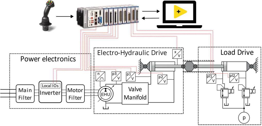
Figure 11 Conceptual schematic of the experimental setup.
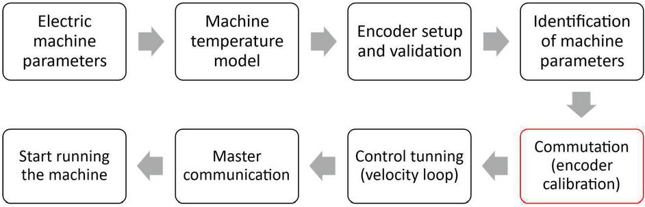
Figure 12 Commissioning steps for the EHU control.
Figure 12 gives the commissioning steps for the EHU control, particularly for the first run of the unit under speed control mode. At the beginning, fundamental parameters of the machine (e.g., peak current, nominal torque, etc.) are required, which can be provided from the designer. The temperature model prevents the machine from overheat by limiting the operation time under intense conditions (e.g., peak current). The encoder validation requires free motion with very low speed (10 rev/min). Then the machine parameters are identified. In the next step, commutation (encoder calibration) is conducted, which is very significant for the machine control.
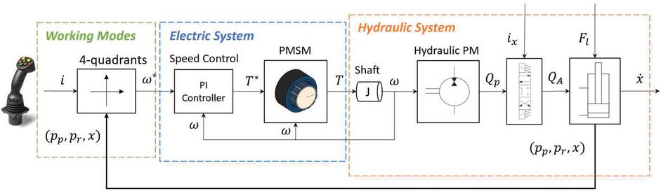
Figure 13 Control of the proposed EHA system.
The synchronous machines are only operational when the current in the stator windings is correctly assigned to the permanent magnetic field of the rotor. The electric machine is not able to provide the maximum torque with the incorrect commutation offset, even risk of moving the machine in an uncontrolled way. However, a good commutation usually requires the motor to spin without load, which is a challenge for the novel designed EHU. Because the electric machine and hydraulic machine are highly integrated, it is only possible to spin the electric motor with the hydraulic machine together. In this case, the starting torque due to the friction of the gears and mechanical couplings may impact the commutation in a negative way. Moreover, since there is no external shaft, it is challenging to spin the motor by applying an external torque. As a result, the commutation might be not optimal with the commission steps of the inverter device. The commutation offset can be adjusted manually in the operation, i.e., under the same working condition, setting the offset value around the initial one until the minimum torque command is reached. Nonetheless, in this study, the offset impact is negligible.
After the commutation, the electric machine is fully operational, and it can be used within a speed control algorithm within the EHA system. The velocity loop adopts a PI controller, in which the velocity error is the input, and the torque command to the electric machine is the output. Finally, the communication step aims to integrate the electric machine control with the EHA system. In this study, the EHU speed can be commanded via analog voltage signals. All control functions are achieved in real time within CRIO. Figure 13 gives a conceptual scheme of the EHA control: a speed command is given by a joystick. By measuring the pressure and displacement of the cylinder, the working mode can be identified, and a desired speed is commanded to the EHU. A PI controller is adopted to convert speed to torque command. Hence, the EHU spins and deliver required flow rate to the hydraulic system. By the working mode identification, a digital signal is given to the directional valve to switch from different modes and on/off.
4 Results
The tests for extension and retraction are conducted with the goal to verify the EHA performance in a realistic duty cycle of the compact loader. Hence, the actuation velocities are controlled to fulfill the boom raising and lowering cycles, and the load force is set to reflect the loading conditions of the vehicle (i.e., both resistive and overrunning conditions).
Figure 14 represents the experimental results with around 20 kN load force for extension and retraction, which is the working condition in quadrant 1 and quadrant 4 in Figure 2.
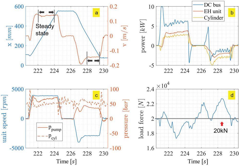
Figure 14 Experimental results with about 20 kN load force applied on the cylinder.
Figure 14(a) shows the displacement of the cylinder and the actuation velocity. Referred to the time axis, resistive extension happens from about 222 s to 224 s, while assistive retraction happens from about 228 s to 229.5 s. Because the command is given by an operator via a joystick, in steady state the velocity is not perfectly a constant. In transition phases some overshoot may happen due to operator commands.
Figure 14(b) gives the power of the DC bus (demanded power by the inverter), EH unit (i.e., output power to the hydraulic circuit in resistive conditions, or input power from the hydraulic system in overrunning conditions), and the cylinder. The values are positive in resistive phase and become negative in overrunning conditions. The sign of the power gives the direction of the power flow, and the difference of the power reflects the losses in the system.
The DC bus power is measured directly via the inverter device, which is the input of the overall system. The EHU power is calculated as the product of the pressure and flow rate at the pump outlet, as given in Equation (10).
| (10) |
The cylinder power is obtained as the product of the measured actuation velocity and the loading force. The formula is given in Equation (11).
| (11) |
Figure 14(c) represents the EHU speed and outlet pressure. The piston side pressure of the cylinder is also plotted as a comparison. The different between the and is the pressure drop through the hydraulic circuit. This measurement is conducted with 100% speed command via the joystick, and the flow rate through the valves can achieve up to 45 L/min, resulting in the pressure drop of about 10 bar.
Figure 14(d) gives the external load force applied to the EHA cylinder by the load module. The force is set to 20 kN, which is close to the force of the boom cylinder with an empty bucket on the compact loader, as shown in the plot. Nonetheless, in a real duty cycle, the load always fluctuates, so the constant load force is not the request for the verification of the proposed system.
Regarding the energy performance, analysis is conducted based on a steady state, as highlighted in Figure 14(a). This highlighted window shows the steady state for the resistive extension phase, and other working conditions will follow the same principle. The recorded data within the steady-state window is averaged in the step range to evaluate the energy performance, such as power, efficiency, etc.
Figure 15 represents the measurements from the inverter device, including the speed (measured from the encoder), torque (calculated according to the measured current) in the upper plot, and power (DC bus power, and input power of the electric motor) in the lower plot. The difference in the power plot is the losses of the inverter device, which is negligible compared to the power level in this application. The efficiency of the inverter device is greater than 97% in steady state from the measurements.
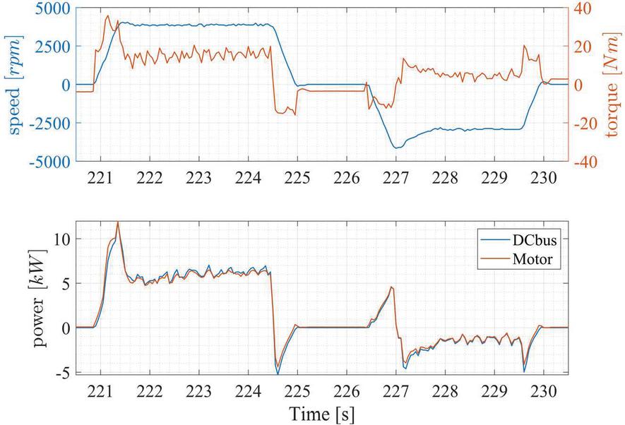
Figure 15 Power measurements from the inverter setup, cycle with 20 kN load.

Figure 16 Power flow of the proposed EHA, extension, and retraction with 20 kN load.
Figure 16 gives a graphical representation of the power flow corresponding to the steady state highlighted in Figures 14 and 15. The numbers indicated in the figure refer to the measured power. From the power source of the inverter to the cylinder, the diagram shows the input/output power of each part in the system and the corresponding power losses.
In the resistive extension phase, the EHU has the most power losses of 2.45 kW. The overall efficiency of the EHU is about 60%. The throttling of the hydraulic circuit wastes 0.79 kW due to the high flow rate required in this phase. In assistive condition, the power flow reverses direction. The efficiency of the EHU is still around 60%. The throttling loss is 0.93 kW, which contributes most of the losses. However, the throttling loss resulting from the pressure drop is only related to the flow rate, but not the load force of the cylinder. Hence, better efficiency can be expected with a higher load force (here the condition is representative of the empty bucket).
It is important to observe that past results discussed in [15] showed higher efficiency, close to 70% in the same conditions. However, these past results were made by using commercial, non-integrated components for the EHU. Therefore, the current energy performance of the prototypes EHU limits the efficiency of the EHA system. This penalization is due to the inaccuracies of the EHU design and manufacture. In fact, the EHU is a first prototype made from the simulation, it does not adopt optimal seals and suffers from some machining imperfections that affect the thickness of the plates and the flatness of their surface facing the gear lateral surface, which could be addressed at a second design refinement phase. According to the power flow scheme, the efficiency of the EHU is about 60% in both conditions, and the system efficiency is limited to about 45%.
To further investigate the performance of the EHU, Figure 17 shows the measurements in terms of the EHU efficiencies.
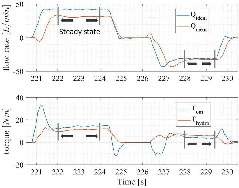
Figure 17 Measurements of the EHU regarding efficiencies.
The upper plot gives the flow rate, from which the volumetric efficiency can be calculated, as shown in Equations (12), (13), and (14), for both pumping and motoring modes. is obtained at the cylinder ports, so in each transition phase there is a delay due to the switch of the directional valve. However, focusing on the steady state this phenomenon does not impact.
| (12) | |
| (13) | |
| (14) |
The lower plot shows the measured torque. The hydro-mechanical efficiency is calculated using (15) and (16). This efficiency is for the EHU including the losses of hydraulic machine and electric machine. The electric torque is high during transients, because the EHU is commanded to accelerate/decelerate to reach the desired speed value in a fast way.
| (15) | |
| (16) |
Table 7 The efficiencies of the EHU during the steady state operation
| Pumping Mode | Motoring Mode | |
| ( rpm, bar) | ( rpm, bar) | |
| Volumetric efficiency | ||
| Hydro-mechanical efficiency | ||
| Overall efficiency |
Table 7 summarizes the efficiencies of the EHU in the steady-state conditions. In pumping mode, the speed is higher than that of motoring mode due to the operator commands. The outlet pressure is also higher resulting from the direction of the flow and the throttling losses in the directional valve. The leakage of the unit is noticeable with a volumetric efficiency of 76.1%. The overall efficiency is about 60%. Instead, in the motoring mode, the hydro-mechanical losses become more obvious, with a hydro-mechanical efficiency of 65%.
The proposed EHA system is capable of four-quadrant functionality. To verify it, assistive extension and resistive retraction phases are also tested. Figure 18 shows the one example with loading force of about 10 kN (i.e., the force direction is opposite to the conditions given in Figure 14). These operation points are included in the quadrant 2 and 3 in Figure 2. The definition of Figure 18(a–d) is the same with Figure 14(a–d). The analysis of the energy performance and efficiency calculations can be conducted with the same methods detailed in the previous paragraphs. The load drive of the test rig is not good at controlling relative low force (10 kN), because it is sized for the boom raising/lowering cycle, not the bucket cycle shown in Figure 18. Hence, the steady state is not as good as the one shown in Figure 14, especially during retraction. Nevertheless, regarding the energy performance the boom cycle is the focus because of the greater power level and more potential to recuperate energy. More studies would be conducted when implementing the EHA system on the reference vehicle.
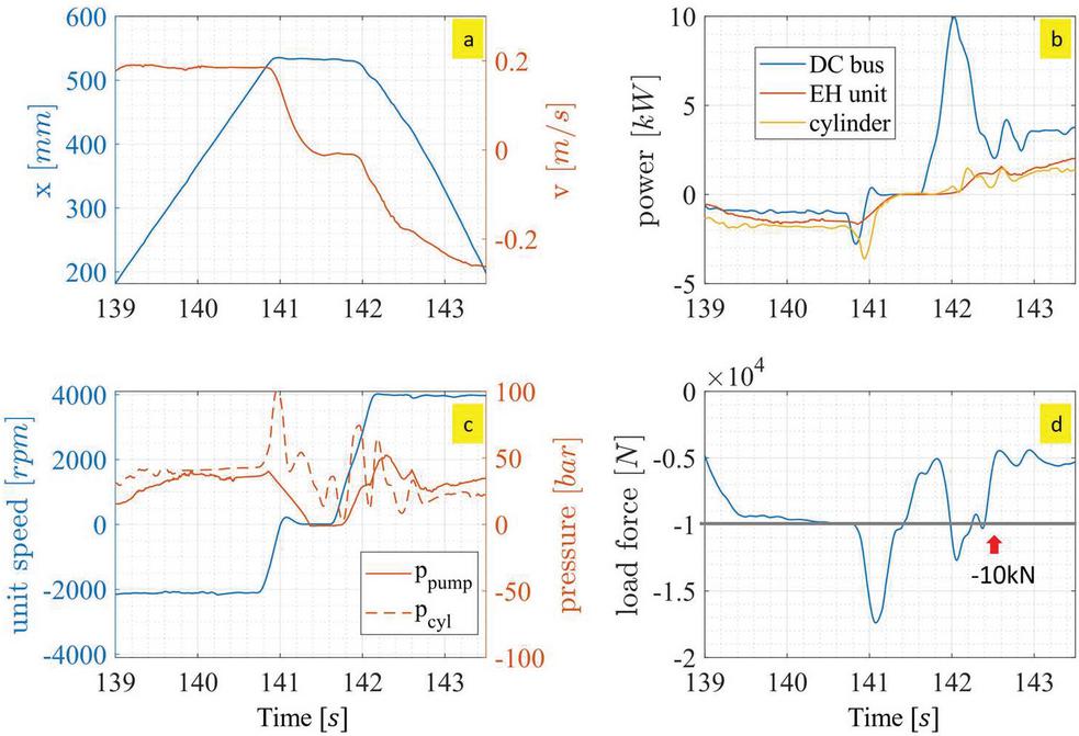
Figure 18 Experimental results with about 10 kN load force applied on the cylinder.
Based on the measurements from the test rig, Figure 19 summarizes the energy performance in four quadrants showing the EHA and EHU total efficiency using a bar chart. The icon of the compact loader represents the four-quadrant working conditions corresponding to Figure 2 (i.e., raising/ lowering boom, tilting bucket up/down in 4-quadrants). As shown in the figure, all four-quadrant functionality of the proposed EHA is verified under realistic loading cycles on the test rig.
The system efficiency is not quite high due to the limitation of the EHU performance, as it is still in prototype phase. The efficiency of the proposed system can reach about 60% in resistive phase, and about 67% in assistive phase with energy regeneration. However, the EHU under test is a prototype and its performance can be improved with certain adjustment regarding the manufacturing and assembly process.

Figure 19 Energy performance in four-quadrants of the proposed EHA system.
After testing the EHA system on the dedicated test rig, the system is implemented on the reference machine for demonstration aiming to drive both the functions of the vehicle. Since the boom actuation is the main target the study for the consideration of energy consumption and regeneration, below are reported the preliminary results of the EHU efficiencies with boom cycle.
More precisely, Figure 20 summarizes the mechanical, volumetric, and total efficiency of the unit when the boom function is actuated at different velocity values with empty bucket. The measurements range span from positive speed values (x-axis), which correspond to the pumping phase of the EHU (i.e., hydraulic pump electric motor), to negative values, which correspond to the regenerative phase of the EHU (i.e., hydraulic motor generator). Starting from null values of velocity and incrementing the velocity in pumping mode is possible to see the pressure increasing. The increment is due to the friction of the mechanism and the hydraulic resistance of the circuit, which becomes more prominent with higher actuation speed and flow rate. As for the motoring mode, the resistance of the circuit and friction of the mechanism also increases with the actuation velocity but in opposite direction. In this case these actions mitigate the differential pressure built across the HM and the torque available to rotate the EHU.
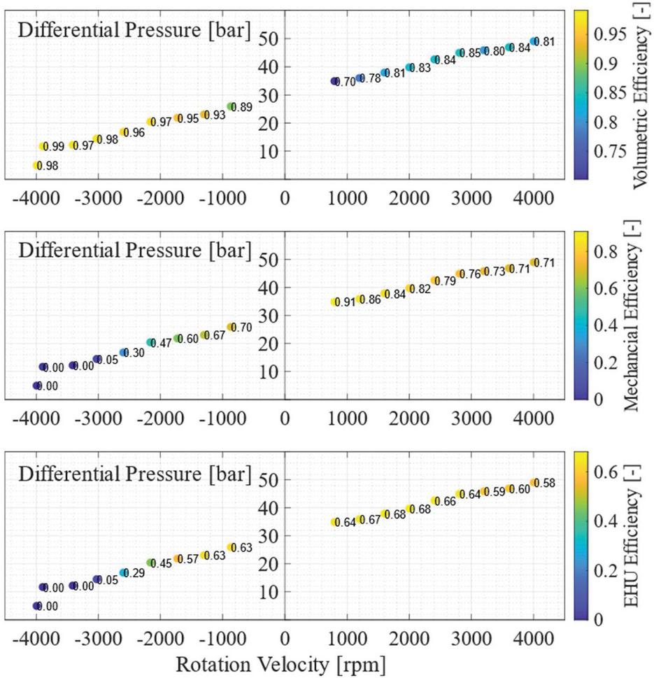
Figure 20 Volumetric, mechanical, and total efficiency of the EHU.
Therefore, the EHU rotating at greater rotation velocity generates a smaller differential pressure. More insights can be gained observing how the efficiency varies depending on the operating conditions.
In the first plot of Figure 20 is highlighted the volumetric efficiency. In pumping mode, the volumetric efficiency of the unit increases first, and then maintains a relative constant value. At lower velocity, the leakage mitigation effect provided by the increment of velocity is predominant with respect to the effect provided by the increment of differential pressure. At higher velocity, however, the two effects balance out producing a roughly constant volumetric efficiency from 2000 to 4000 rpm. In the plot quadrant illustrating the performance in motoring mode it is possible to see the volumetric efficiency increasing with the rotation velocity. This is expected since at higher rotation velocity the hydraulic machine produces a smaller fluid resistance and therefore reduced leakages.
The second plot of Figure 20 shows the mechanical efficiency. In pumping mode, it is possible to see that increasing the velocity corresponds to a decrement of mechanical efficiency. With higher velocity, the hydromechanical losses generated in the lubricated interfaces increase. The hydromechanical losses affect the mechanical efficiency of the EHU also in motoring mode. In fact, as for the pumping mode, an increment of rotation velocity produces a decrement of mechanical efficiency. Faster the EHU rotates, more of the torque generated by the differential pressure is used to overcome the losses in the lubricated gaps. Between 3000 and 4000 rpm it is possible to observe null measured efficiency. These values point out the necessity of providing energy to the EHU to ensure the actuator motion at such velocity values. This is because in that velocity range the differential pressure built is between 5 and 15 bar, which are not enough to overcome the friction generated by the moving parts of the hydraulic machine.
The results measured on the reference vehicle also further validate the data acquired on the test rig. The EHU efficiencies match well in Figures 19 and 20.
5 Conclusion and Outlook
The paper presents the experimental verification of an open-circuit EHA system with a novel-designed EHU. The open-circuit design of the EHA represents an effective solution to implement distributed throttle-less hydraulic actuation, keeping a centralized layout for the tank and the oil conditioning system. The proposed layout allows implementing the EHA without requiring substantial modification of existing cylinders present in a vehicle. The EHU integrates an external spur gear hydraulic machine and a permanent magnet synchronous electric machine. The EHU design enhances compactness, components reduction, and power density. The system performance is verified on a dedicated test rig, which can actively control the load force of the cylinder. Experimental results validate the system functionality for operation in four quadrants with respect to commanded speed and external load. The measured efficiency of the system can reach 54% and, as of now, is limited by the efficiency of the EHU prototype which is about 60% in pumping and motoring modes with 20 kN load. This study is a showcase of the proposed EHA system, thus opening new possibilities for a new generation of EHA that are more practical for implementation with less special requirements.
Future work will extend the test to the actual implementation in the reference off-road vehicle, focusing on the efficiency performance and energy saving capability of the proposed EHA system.
Acknowledgment
The authors wish to thank Case New Holland Industrial for the support of the reference vehicle used for the experiments. The project is funded by the Department of Energy, USA (DOE project DE-EE0008334, ‘Individual Electro-Hydraulic Drives for Off-Road Vehicles’).
Nomenclature
[1] J.-C. Maré, Aerospace actuators 2: signal-by-wire and power-by-wire. John Wiley & Sons, 2017.
[2] R. Navarro, “Performance of an electro-hydrostatic actuator on the F-18 systems research aircraft,” NASA Technical Memorandum, no. 206224, 1997, https://www.nasa.gov/centers/dryden/pdf/88524main\_H-2210.pdf.
[3] D. van den Bossche, “The a380 Flight Control Electrohydrostatic Actuators,” 25Th International Congress of the Aeronautical Sciences, pp. 1–8, 2006.
[4] G. Altare and A. Vacca, “A Design Solution for Efficient and Compact Electro-hydraulic Actuators,” Procedia Engineering, vol. 106, pp. 8–16, 2015, https://doi.org/10.1016/j.proeng.2015.06.003.
[5] Bosch Rexroth. (2019). “Servo-hydraulic actuator – SHA,” Servo-Hydraulic Actuator – SHA (bosch.com).
[6] Parker Hannifin. (2021). “Compact EHA – electro-hydraulic actuators for high power density applications,” Compact Electro-Hydraulic Actuator (EHA), High Power Linear Actuator Motor | Parker.
[7] D. B. Beck, D. E. Fischer, D. G. Kolks, D. J. Lübbert, D. S. Michel, and D. M. Schneider, “Novel System Architectures by Individual Drives,” The 10th International Fluid Power Conference, pp. 29–62, 2016.
[8] T. Pietrzyk, D. Roth, K. Schmitz, and G. Jacobs, “Design study of a high-speed power unit for electro-hydraulic actuators (EHA),” The 11th International Fluid Power Conference, 2018.
[9] Bosch Rexroth. (2015). “Intelligent self-sufficient systems for powerful drive tasks,” Intelligent self-sufficient systems for powerful drive tasks | Bosch Rexroth AG.
[10] S. Michel and J. Weber, “Prediction of the thermo-energetic behaviour of an electro-hydraulic compact drive,” Proceedings of the 10th International Fluid Power Conference, pp. 219–234, 2016.
[11] S. Ketelsen and S. Michel, “Thermo-Hydraulic Modelling and Experimental Validation of an Electro-Hydraulic Compact Drive,” Energies, vol. 14, no. 9, p. 2375, 2021. doi: 10.3390/en14092375.
[12] S. Qu, D. Fassbender, A. Vacca, E. Busquets, and U. Neumann, “A closed circuit electro-hydraulic actuator with energy recuperation capability,” The 12th International Fluid Power Conference (12. IFK), 2020, pp. 89–98. doi: 10.25368/2020.16.
[13] S. Qu, D. Fassbender, A. Vacca, and E. Busquets, “Formulation, Design and Experimental Verification of an Open Circuit Electro-Hydraulic Actuator,” 2020 IEEE Global Fluid Power Society PhD Symposium (GFPS), 2020, pp. 129–136.
[14] S. Qu, D. Fassbender, A. Vacca, and E. Busquets, “A Cost-Effective Electro-Hydraulic Actuator Solution with Open Circuit Architecture,” International Journal of Fluid Power, vol. 22, no. 2, pp. 233–258, 2021. doi: 10.13052/ijfp1439-9776.2224.
[15] S. Qu, D. Fassbender, A. Vacca, and E. Busquets, “A high-efficient solution for electro-hydraulic actuators with energy regeneration capability,” Energy, vol. 216, p. 119291, 2020. doi: 10.1016/j.energy.2020.119291.
[16] S. Qu, D. Fassbender, A. Vacca, and E. Busquets, “Development of a Lumped-Parameter Thermal Model for Electro-Hydraulic Actuators,” The 10th International Conference on Fluid Power Transmission and Control (ICFP 2021), 2021.
[17] Vacca, A., Ransegnola, T., Zappaterra, F., Sudhoff, S.D., Swanson, R.R. and Busquets, E., Purdue Research Foundation, 2021. Integrated electro-hydraulic machine. U.S. Patent Application 17/163,407.
[18] Zappaterra, F., Vacca, A., Sudhoff, S.D., “A compact design for an electric driven hydraulic gear machine capable of multiple quadrant operation.” Mechanism and Machine Theory 177 (2022).
[19] Ransegnola, T. “A Strongly Coupled Simulation Model of Positive Displacement Machines for Design and Optimization.” PhD diss., Purdue University Graduate School, 2020.
[20] Vacca, A. and Guidetti, M., “Modelling and experimental validation of external spur gear machines for fluid power applications.” Simulation Modelling Practice and Theory, 19(9), pp. 2007–2031, 2011.
[21] Rituraj, Vacca, A., 2021, “Investigation of flow through curved constrictions for leakage flow modelling in hydraulic gear pumps,” Mechanical Systems and Signal Processing, 153(15), doi: 10.1016/j.ymssp.2020.107503.
[22] Sudhoff, Scott D. “Power magnetic devices: a multi-objective design approach.” John Wiley & Sons, 2014.
[23] Dhar, S., Vacca, A., 2012, “A Novel CFD- Axial Motion Coupled Model for the Axial Balance of Lateral Bushings in External Gear Machines,” Elsevier Simulation and Modeling Practice and Theory, 2012; 26: 60–76.
[24] Dhar, S., Vacca, A., 2013, “A Fluid Structure Interaction-EHD Model of the Lubricating Gaps in External Gear Machines: Formulation and Validation,” Tribology International (Elsevier) 62 (2013) 78–90.
[25] Ransegnola, T., Vacca, A., 2020, “Virtual design and analysis of the balancing element of an external gear machine considering cavitation and mixed lubrication effects,” 2020 Global Fluid Power Society PhD Symposium, October 19-21, 2020, Guilin, China.
Biographies

Shaoyang Qu is currently a system engineer in Bosch Rexroth US, drive control – mobile hydraulics team. He got the Ph.D. degree in the School of Mechanical Engineering at Purdue University, where he worked in Maha Fluid Power Research Center on electrification of mobile hydraulics since 2018. Before that, he attended Tsinghua University in Beijing, China, where he received his B.E. in Mechanical Engineering and B.S. in Business administration in 2018. His work mainly focuses on the R&D work on electrified solutions of the state-of-the-art hydraulic systems and the development of next generation electrification platforms.

Federico Zappaterra completed his studies in Italy where he graduated with a master’s degree from Polytechnic of Turin. Currently he is a research assistant at Maha Fluid Power Research Center where he focuses on the design of electro-hydraulic unit and electrified system for mobile fluid power applications.

Andrea Vacca is a the Maha Fluid Power Faculty Chair and a Professor at Purdue University. He leads the Maha Fluid Power Research Center which has more than 25 graduate researchers working on various topics related to fluid power and motion control technology.
Dr. Vacca completed his studies in Italy (Ph.D. from the University of Florence in 2005) and he joined Purdue University in 2010. Fluid power technology has been Dr. Vacca’s major research interest since 2002. Dr. Vacca authored the textbook “Hydraulic Fluid Power” by Wiley and about 200 technical papers, most of them published in international journals or referred conferences. He is the Chair of the Fluid Power Systems and Technology Division (FPST) of the American Society of Mechanical Engineers (ASME), and a former chair of the Fluid Power Division of the Society of Automotive Engineers (SAE). Dr. Vacca is also one of the Directors of the Global Fluid Power Society (GFPS). Furthermore, he is also the Editor in Chief of the International Journal of Fluid Power. Dr. Vacca received the 2019 J. Braham medal of the Institution of the Mechanical Engineers (IMechE).

Zifan Liu, has been the system engineer with responsibilities on electronics and electrification at Bosch Rexroth North America since April 2018. Zifan has been involved in the development of electrification platform, eLION, of Bosch Rexroth, including electric components and software packages. Zifan also assists with the setup of customer vehicles and calibrates various Bosch Rexroth functional bundles with specific focus on next generation electric systems in off-highway applications.

Enrique Busquets has been the engineering director with regional product and business development responsibility on electronics, software, telematics, and electrification at Bosch Rexroth North America since April 2021. Additionally, Enrique has been responsible for the testing and validation infrastructure in North America since 2018 and innovations since 2016.
Previously, Enrique Busquets was the engineering manager responsible for systems and software development at Bosch Rexroth North America from 2018 to 2021. The technology focus was on mobile applications with electronified hydraulics and electrified systems.
Enrique holds a bachelor’s degree from the University of Texas at El Paso and a master’s, and doctorate degree in mechanical engineering from Purdue University with emphasis on hydraulics and electronic controls.
In addition to his professional activities, Dr. Enrique Busquets is the Bosch Rexroth industry sponsor and representative at the Maha research center and the National Fluid Power association.
International Journal of Fluid Power, Vol. 24_2, 327–360.
doi: 10.13052/ijfp1439-9776.2427
© 2023 River Publishers