A New Elastic Non Contacting Sealing Concept for Valves
Scherrer Matthias*, Scheidl Rudolf and Luckachev Evgeny
Institute for Machine Design and Hydraulic Drives, Johannes Kepler University, Linz, Austria
E-mail: matthias.scherrer@jku.at; rudolf.scheidl@jku.at
*Corresponding Author
Received 09 June 2022; Accepted 21 July 2022; Publication 28 September 2022
Abstract
The hydraulic binary counter concept was proposed as a means to realize compact and lightweight digital hydraulic cylinder drives for exoskeleton actuation. This counter principle is based on hydraulically actuated switching valves which have a hysteretic response with respect to the pilot pressure. Manufacturing tolerances of the tiny components caused unexpected high leakage which, in turn, led to a malfunction of the system.
In this paper a new sealing concept, is introduced to solve this problem. It is based on a non-contact seal (sealing gap), which exploits a self-regulating, elasto-hydrodynamic effect to reduce a rather large initial gap h0 – to allow a rough tolerance – into a very small sealing gap h(x) to avoid dry friction of valve spool movement on the one hand but have very small leakage on the other hand.
As sealing, an annular flexible ring made, e.g. of PTFE, is used which combines sufficient flexibility to allow this self adapting mechanism to a sufficient extent and to stay the high pressure loads.
For the mathematical analysis of the concept, an approximate elasto-hydrodynamic analytical model is used. It sets the gap pressure, obtained from the Reynold’s equation for the sealing gap, the elastic restoring forces of the sealing ring, and the imparting pressure in equilibrium.
The sealing concept is then simulated with a numerical model built with the finite element code ABAQUS, this results are compared with the one of the analytical model.
It solves the Reynolds equation by a user defined subroutine. The simulation results indicate that this sealing principle delivers way better results than standard gap seals despite its rough manufacturing tolerances with one order of magnitude higher tolerance ranges. The application of this concept is not limited to small valves as needed for exoskeleton hydraulics but can be transferred to conventional type of hydraulics as well.
Keywords: Digital hydraulic cylinder drives, exoskeleton, new sealing concept, elastic sealing.
1 Introduction
In their attempts to contribute to the progress of exoskeleton technologies by lightweight and efficient hydraulic actuators the authors studied a multi-chamber cylinder drive in [1] and [2]. A special hydraulic piloting concept based on the binary hydraulic counter idea was proposed in [3] to save solenoid weight of the many valves needed in a multi chamber cylinder. The concept and a first embodiment design are sketched in Figure 1.
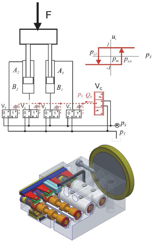
Figure 1 Concept and prototypal embodiment design of a four bit binary counter. Size of counter in comparison to a one Euro coin.
In [4] reports about high internal leakage (3.3l/min @100 bar) of this prototype, due to inaccurate manufacturing; this resulted from the limited manufacturing capabilities feasible at the University manufacturing labs which is limited to tolerances not better than 12 micrometer for a 4 mm piston diameter.
Besides this specific situation for the prototypal exoskeleton drive the realization of the tight dimensional tolerances necessary for a desirable low leakage even for conventional valve sizes is a strong cost factor. Therefore, it is worth considering new concepts for the proper sealing of valve spools which – despite coarse manufacturing tolerances – provide low leakage on the one hand but avoid any dry friction effect on the other hand. Negligible dry friction is necessary to achieve a fast and accurate response with a small actuation force and power. Contactless seals avoid dry friction but their cost-effective manufacturing means high gap tolerances and, in turn, high leakage.
To overcome this trade-off a self–adapting, non-contact seal exploiting elasto-hydrodynamic effects and its theoretical analysis is presented in this paper.
Elasto-hydrodynamic effects may influence the properties of valves. A wear problem in the valves of Diesel common rail injectors caused by an adverse elasto-hydrodynamic effect in the sealing gap and its solution turning this effect into a beneficial one by a minor redesign of involved components are studied in [5]. In [6] the solution of a comparable problem in a fast hydraulic switching valve is presented. The idea to exploit the softness of polymer materials to amplify elasto-hydrodynamic effects is realized in [7] to provide a non-contacting, hence, low friction guidance of a piston in a bore.
The work in this paper focuses on the sealing rather than the guidance effect but makes use of plastic material high compliance too.
2 Seal – Concept
As sealing element, an annular flexible ring made of plastic material, e.g. of polytetrafluorethylene, is used. It is placed in a circumferential groove at the sealing lands of the valve, as indicated in Figure 2. At the current stage of the project only the functioning of that seal for the lands # 1 and # 3 is considered, the investigation for the land # 2 is more challenging because of the drill hole above the sealing and will be done later.
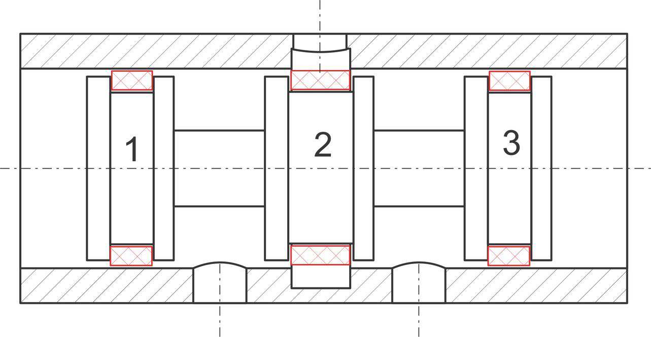
Figure 2 Basic use of seal in a spool valve.
The basic working principle is explained in Figure 3. With its initial shape a gap parallel sealing gap h with the bore is formed. It is intended that a sufficiently small leakage can be achieved with an initial gap size h which is one order of magnitude higher than required in conventional sealing gaps of valves which rely on stiff materials and a precise manufacturing. A gap exists also on its inner side with the spool body and with the lateral flange on the lower pressure side (p in Figure 3). A parallel sealing gap exhibits a linear pressure distribution, as shown in the upper sketch of Figure 3. The sealing ring is loaded by the higher pressure p on its inner side and on its high pressure front and by the gap pressure p(x) on its outer side. The difference of inner and outer pressure p causes an elastic, predominantly radial expansion of the ring which is higher where p is higher. This situation is sketched in the lower part of Figure 3. The gap takes approximately a conical shape, smaller at the low pressure side. In turn, the pressure distribution changes and a substantial pressure difference exists only in a domain next to the low pressure side. If the gap at the p side is fully closed the gap pressures is uniformly p and p is zero. This extreme deformation is prohibited by the elastic restoring forces of the ring. This consideration suggests that the ring adopts a position between the initial un-deformed position with a uniform h and a position with fully closed gap at the p side.
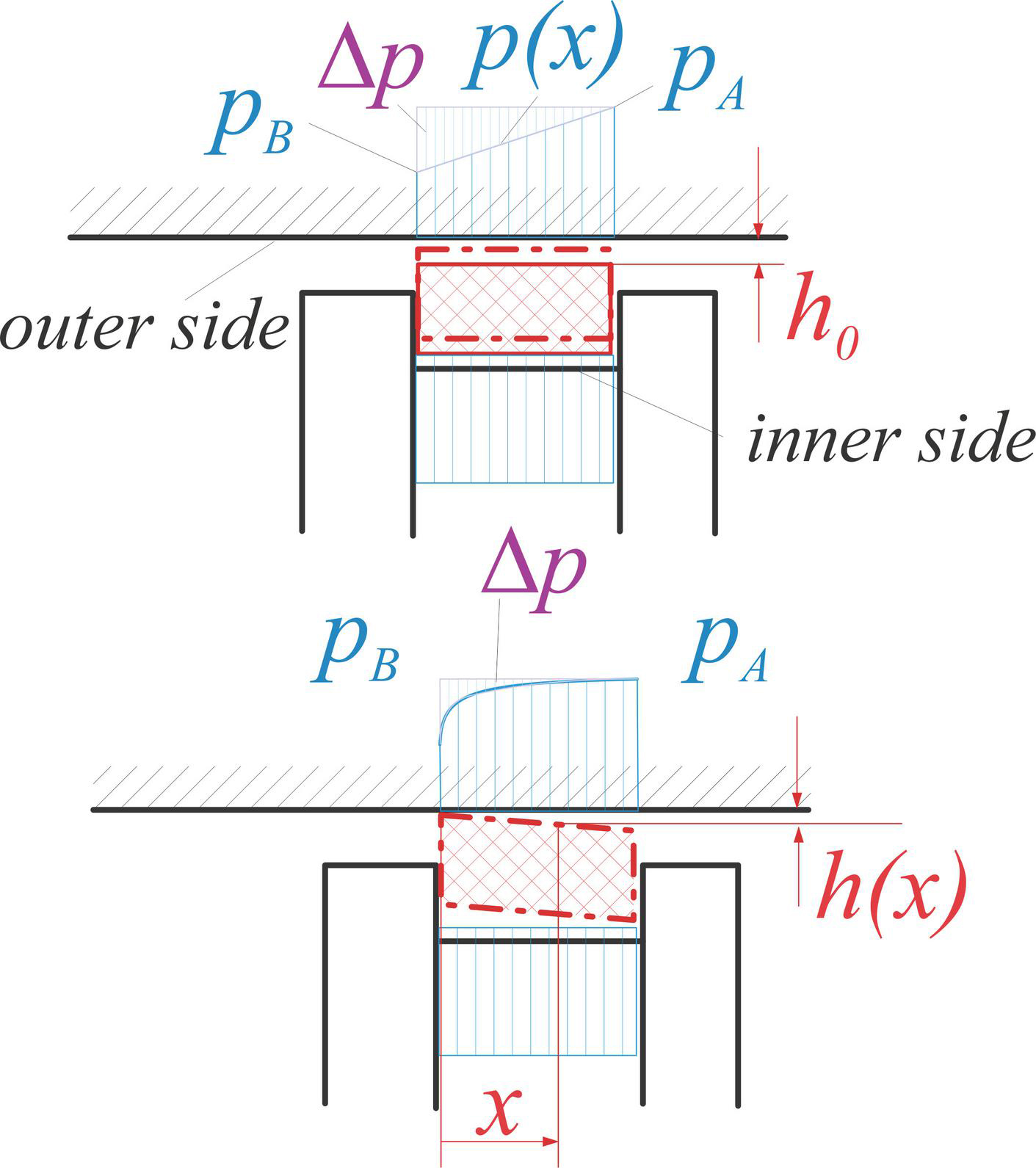
Figure 3 Function principle of the hydrodynamic sealing concept: upper picture: sealing in the initial position with uniform gap h0 and the pressure difference p; lower picture: deformed sealing ring and variable gap and resulting pressure difference p.
3 Analytical Model
An approximate analytical model which represents the basic idea of the sealing principle as outlined in the last section is presented in this section. It combines two phenomena, the elastic deformation of the sealing ring and the pressure distribution in the sealing gap.
3.1 Mathematical Description
The ring deformation is modeled as an axisymmetric radial displacement u, linearly distributed over the axial length coordinate x. The original constant gap h becomes a linearly varying gap h(x). The ring cross section is assumed to preserve its shape; hence, the deformation field depends on x only and only radial strains and stresses occur. The corresponding set of equations reads, as follows
| (1) | |
| (2) |
The displacement field is parametrized by u and , and represents a Ritz approach for the approximate solution of the problem under study.
The pressure distribution in the gap is computed by an exact solution of the Reynolds equation with given pressures on both boundaries.
| (3) | |
| (4) |
The solution reads
| (5) |
The ring deformation model is derived by combining the Ritz approach (2) of the displacement field with a virtual displacement method. The elastic ring deformation part of the total virtual work can be derived from the potential energy functional U of the elastic deformation
| (6) |
with the following expression of the linearized radial strain
| (7) |
The gap pressure field does not have a potential. Its contribution W to the total virtual work is
| (8) | |
| (9) | |
| (10) |
The sealing is pressed to its left contact surface by a total force
| (11) |
A virtual displacement u causes a virtual work of the corresponding friction force
| (12) |
The two equilibrium conditions can be described as:
| (13) | |
| (14) |
With the following simplifications and transformations, the formulas are made dimensionless.
| (15) | |
| (16) | |
| (17) |
Furthermore, some transformations for further simplifications are made
| (18) |
This expressions, (15–18) are inserted in the residuals (13, 14). The Jacobian matrix can be described as:
| (19) |
The solution of the equation is found with the nonlinear system solver in MATLAB for different system pressures. The inputs are the Residuals (13, 14), the Jacobian Matrix (19) and starting values for the solution of and .
With the Hagen-Poiseuille flow profile the leakage over the sealing can be calculated as:
| (20) | |
| (21) |
The actual leakage can be referred to the starting leakage () and a dimensionless expression can be found:
| (22) | |
| (23) |
To achieve a dimensionless, system pressure dependent leakage, Equations (15–18) are inserted in (21) and lead to
| (24) |
The formula (22) represents the maximum leakage flow over the sealing for no displacement and deformation. The dimensionless leakage (23) can be calculated by referring the leakage of (21) to the maximum leakage (22). This maximum leakage shows the linear dependency of the leakage from the system pressure . Also the leakage is increasing with a bigger piston radius , and is cubical dependent from the initial gap height , which results from the Hagen Poiseuille flow profile. A bigger width b and viscosity decrease the leakage.
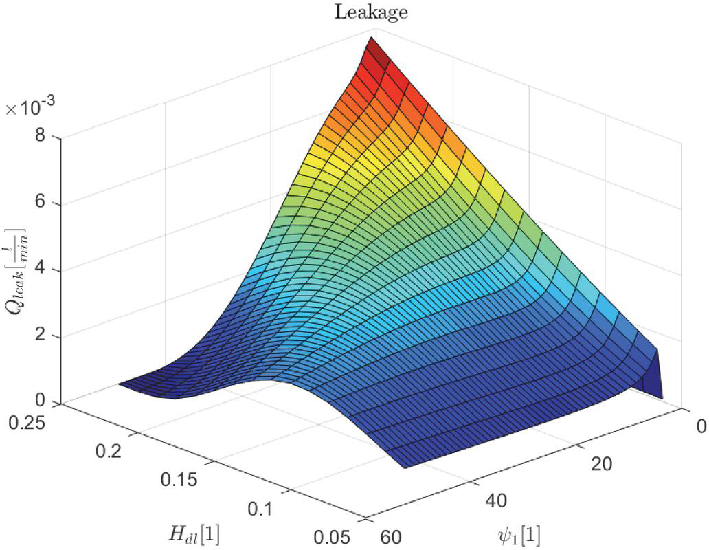
Figure 4 Leakage over the dimensionless difference pressure and the dimensionless height of the sealing.

Figure 5 Leakage over the dimensionless difference pressure and the dimensionless initial gap .

Figure 6 Leakage over the dimensionless difference pressure and the dimensionless width of the sealing.
3.2 Sensitivity Analysis of the Analytical Model
For a better understanding, of the parameter influence on the leakage, in Figures 4–6 the sensitivity of the model can be seen. The leakage is applied over the pressure, the third axis shows the influence to the parameter variation. The variation corresponds from , where the parameters are the dimensionless height of the sealing , the dimensionless initial gap , and the dimensionless width of the sealing . The exact mathematical formulation of these dimensionless variables was already described in formula (15), (16), (17) and (18). The nominal parameters used for the calculations can be seen in Table 1.
In Figure 4 small pressures and big heights of the sealing, lead to a high leakage , while for small heights, pressure independent, the leakage theoretically becomes very small. Since high system pressure cannot always be guaranteed, a thin wall is preferred for the design of the sealing.
The strength of the sealing must be taken into account, if the wall thickness is too small, it begins to bulge and the function can no longer be guaranteed.
In Figure 5 there can be stated, that the leakage decreases significantly with smaller initial gap independent from the system pressure, which is directly corresponding with the manufacturing accuracy of the manufacturing machines. So the reduction of this parameter is limited. Furthermore, this variation has more influence on the leakage than the height of the sealing.
Table 1 Nominal parameters
| Parameter | Value |
| Young Modulus Teflon | MPa |
| Density Teflon | kg/m |
| Poison ratio Teflon | |
| Dynamic viscosity Fluid | Pa s |
| Density Fluid | kg/m |
| Radius of the shell | mm |
| Height of the sealing | mm |
| Length of the sealing | mm |
| Maximum system pressure | bar |
In Figure 6, the influence of the width of the sealing can be seen. For really small widths of the sealing and low pressures, the leakage is extremely increasing. The sealing is not deformed at this point, because of a wrong parametrized width to height relation. For bigger widths, the leakage is nearly pressure independent.
This simplified model already shows the functionality of the sealing concept, because the leakage decreases for higher system pressures. Different parameter variations (Figures 4–6) show different behaviors of the sealing. An ideal design will be discussed after the implementation of the numerical simulation in Chapter V.
4 Finite Element Simulation
The next step was to design the simple concept of the sealing and numerically simulate it with the help of FEM in ABAQUS. The design consists of a wall (rigid body), the deformable sealing (3D deformable body) and the hydraulic gap (Reynold’s User element).
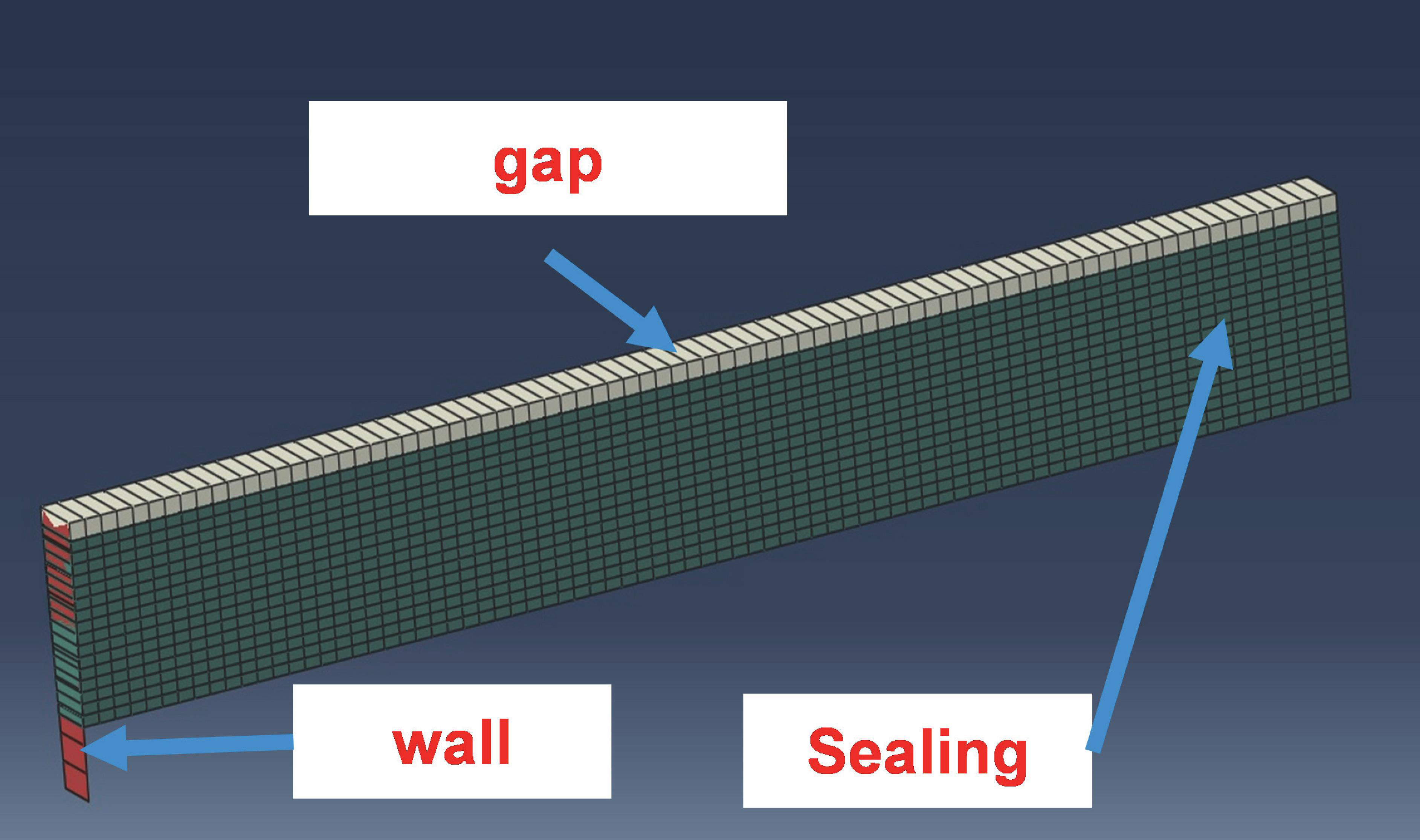
Figure 7 Mesh geometry of the simplified slice modeled in ABAQUS containing the gap (represents the hydraulic fluid), the wall (represents the piston where the sealing is pressed against), and the elastic sealing.
4.1 Reynolds User Element
ABAQUS has the possibility to solve the full Navier-Stokes equation to perform coupled fluid-structural interaction, which is computationally very expensive. To achieve shorter simulation times, a Reynold’s User element, programmed in a user subroutine in FORTRAN, was used for modeling the fluid. This subroutine was already used for different simulations and explained in [8], but is shortly explained again for a better understanding of the method. The pressure distribution can be described with the well-known Reynold’s equation (3). This equation is then discretized by the finite element method. The elastic deformations due to the pressure in the fluid film are calculated using the usual solid finite elements analysis of the solid parts of ABAQUS. The coupling between the gap and the sealing is realized with a tie contact between the master surface (sealing) and the gap (slave). The nodal forces of the slave nodes are estimated from the Reynolds element pressures.
4.2 Boundary Conditions and Modeling
For simplification, the sealing ring was modeled as segment, with an angle . Because of the independence of the pressure in the circumferential direction, this verification is possible without restrictions. The applied boundary conditions are first, rotation and displacement of the wall in all directions is set to zero (Encastre ). Second, the same boundary conditions are also applied for the outer side of the gap. Third, due to the simplification of using a ring segment instead of the whole ring, the displacement in the circumferential directions on the two planar sides of the sealing must also be locked. Fourth, the boundary pressure and are applied. For a first simulation the parameters in Table 1 where used. The contact between the wall and the sealing component, was modelled as a hard contact in normal direction and a colomb friction with a coefficient of in tangential direction. For the meshing of the sealing, an Eight node brick element C3D8 is used.
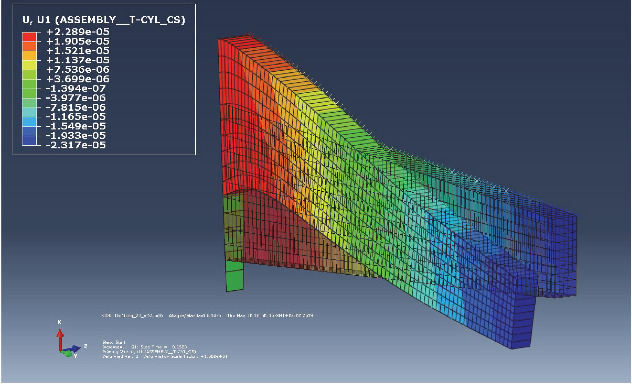
Figure 8 Simulation result, Deformation of the sealing, regarding to a pressure drop over it.
In Figure 8 the deformation of the sealing, caused by high pressure on the right side and low pressure on the left side, can be seen. The sealing is sliding on the wall and comes into an equilibrium of the pressure on upper and lower side. The function of the self-regulation could be approved for different parameters and the results will be discussed in the next chapter.
5 Comparison of Solutions
In this chapter, the solution of the analytical simplified model and the numerical model are compared. In Figure 9 the pressure drop over the sealing can be seen, which has most of its change over the small gap at mm. The smaller the gap, the higher the pressure gradient and the higher the curvature of the deformed sealing in this region.
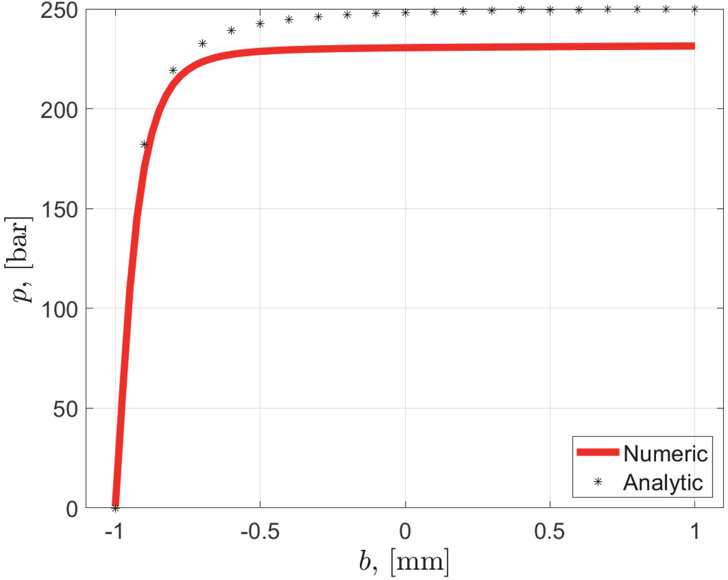
Figure 9 Pressure drop over the width of the sealing gap b for numerical and analytical solution.
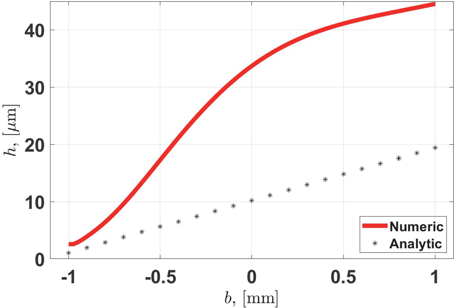
Figure 10 Height of the sealing gap over the width for numerical and analytical solution.
This effect can be seen in Figure 10, where the height of the gap is plotted for the maximum system pressure over the width of the sealing. Of course there are deviations between the two approaches, since the analytical model of simplicity only allows linear deformations of the sealing. So for a more precise model, the approach in formula (1) should be expanded with the curvature as
| (25) |
Solving the equations (shown in Chapter III A, formula (3) to (14)) analytically with this expanded approach of (25) led to many problems and did not really bring any results. Moreover, to get the deformation similar to the numerical model, as can be seen in Figure 10, which is definitely more precise and probably closer to the real solution, a more complex approach than (25) has to be taken. But this leads to unmanageable equations with no analytical solution, that’s why the simple approach of formula (1) is sufficient for a first appraisal.
In Figure 11 the leakage for different simulated parameter settings can be seen. It has to be marked, that for the simulated parameter combinations, the height of the sealing has a big influence on the leakage. But the other parameter variations (red, blue, green) seem to bring much less influence on the result of the leakage. Which means that the smallest sealing should be chosen for the design.
The deviations of the leakage between the analytical and numerical solution in Figure 11 are mainly the amplitude for low pressure values and smaller pressure dependencies of the analytical model. This correlates with the smaller gap at mm (analytical model compared to numerical model, which can be seen in Figure 10), because a smaller gap leads to a lower leakage.
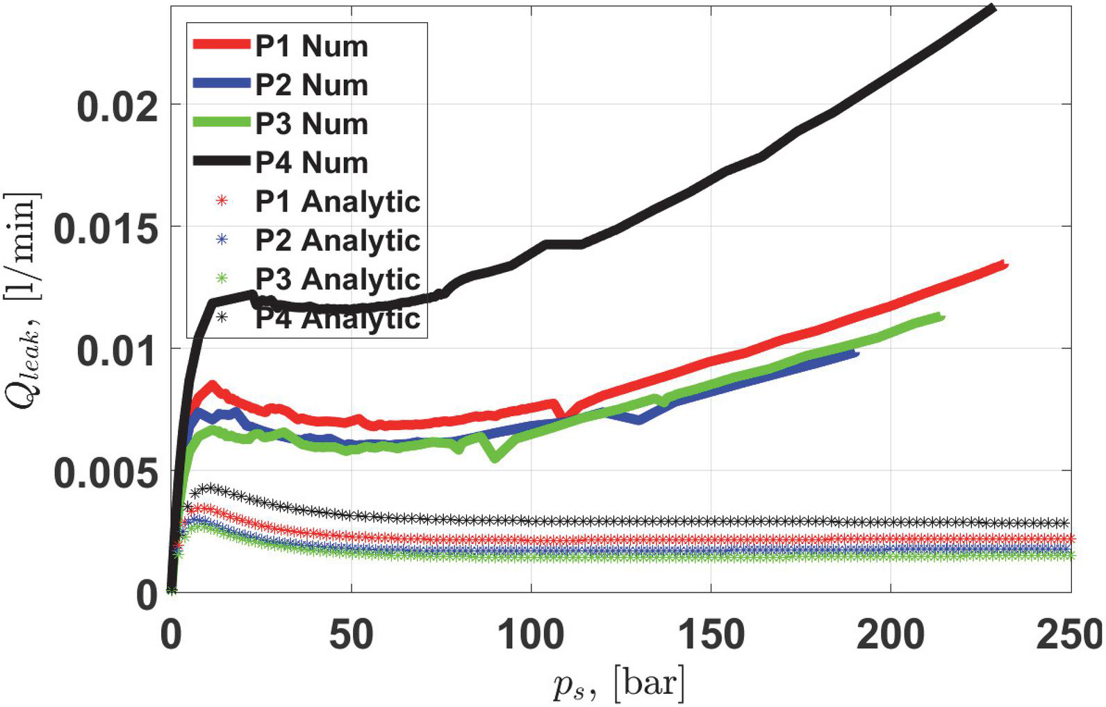
Figure 11 Leakage for different pressures over the sealing gap for numerical and analytical solution.
Table 2 Variated parameters for the numerical and analytical calculations ( is the length of the seal in axial direction, is the height of the seal and the slope on the inner side of the seal)
| Parameter | Values |
| P1 | mm, mm, k 1 |
| P2 | mm, mm, k 0.75 |
| P3 | mm, mm, k 1 |
| P4 | mm, mm, k 0.5 |
It has to be noted, that for thin wall thickness of the sealing, the numerical simulation becomes instable. This is the case when the sealing ring bulges. So this represents the lower limit for the sealing height. Furthermore, also the width should be kept small, because of compactness, and the fact, that the width is not decreasing the leakage significantly.
But, also for a square cross section of the sealing, the functionality of the sealing cannot be fulfilled. So this are the limits for the width of the sealing. The parameters P2 and P2 show the best performance for this simulation and should be chosen for this valve. Overall, the principal functionality of the concept could be shown with both models. However, the functionality of the concept has to be approved with a prototype.
6 Summary and Conclusion
In order to achieve small leaks in hydraulic valves, it is possible to use contact seals, but this has the major disadvantage of increased friction in the system. When using non-contact seals, there is the problem of increased leakage when the gap is not manufactured with sufficient accuracy. As a new approach, a new concept of a contactless, elastic seal was presented in this paper. Using a linear approach to deformation, a simple model was derived and initial insights into behavior were examined. Furthermore, the seal was simulated with a FEM calculation in ABAQUS and the deformation with a corresponding pressure drop was simulated using a Reynolds element. This results in the leakage, which already causes a leakage 300 times smaller than the gap seal used for the first prototype. Thus, the function of the concept is confirmed with both the analytical and numerical model. In order to guarantee the function, the geometry of the seal must be selected correctly. The limits are the buckling of the seal, compactness, and the possibility of deformation due to the cross section. The next steps are the test set-up, using the prototype of the seals and the verification of the calculation results.
Nomenclature
| h | initial sealing gap |
| p | pressure in the gap |
| x | coordinate in axial direction |
| coordinate in circumferential direction | |
| q | coordinate in radial direction |
| p | low pressure on the left side of the sealing gap |
| p | high pressure on the right side of the sealing gap |
| p | system pressure |
| p | pressure drop over the sealing |
| h | varying height of the sealing gap |
| u | displacement in radial direction |
| radial strains | |
| radial stress | |
| radial displacement | |
| angle of the deformed sealing | |
| viscosity of the fluid | |
| velocity of the fluid as first boundary condition | |
| velocity of the fluid as second boundary condition | |
| b | width of the sealing |
| U | inner energy |
| V | volume |
| E | Compression modulus |
| W | Outer energy |
| Axial force, resulting from the system pressure | |
| pressure related to compression modulus | |
| ratio of compressibility | |
| displacement related to the initial gap height | |
| width related to the radius | |
| height related to the radius | |
| initial height related to the radius |
References
[1] Holl E., Scheidl R., Eshkabilov S. (2017). Simulation Study of a Digital Hydraulic Drive for a Knee Joint Exoskeleton. In Proceedings of the 2017 ASME/BATH Symposium on Fluid Power and Motion Control FPMC2017, October 16–20, 2017, Sarasota, FL, USA. Paper No. FPMC2017-4220.
[2] Scheidl R. (2017). Digital Fluid Power for Exoskeleton Actuation – Guidelines, Opportunities, Challenges. In DFP17; Proceedings of the 9th Workshop on Digital Fluid Power (DFP17), 7–8 September, 2017, Aalborg, Denmark.
[3] Scheidl R., Mittlböck S.: A Hydraulic Piloting Concept of a Digital Cylinder Drive for Exoskeletons: Proceedings of Bath/ASME Symposium on Fluid Power and Motion Control, FPMC 2018, 12–14 September 2018, University of Bath, Bath, UK, no. FPMC2018-8875, 2018.
[4] Scherrer M., Scheidl R., Mittlböck S. (2019) Embodymentdesign of a hydraulic binary counter for exoskeleton use – problems and new solutions. In Proceedings of the 10th Workshop on Digital Fluid Power, February 28–March 1, 2019, Linz, Austria.
[5] Mitter R.: Rechnerische Untersuchung eines Verschleißproblems im Injektor eines Common Rail Dieseleinspritzsystems auf Basis eines elasto-hydrodynamischen Modells – Ventilkolbenführung und Dichtfunktion gegen Hochdruck. Diploma thesis, Johannes Kepler University Linz, Asutria, 2000.
[6] Winkler B., Mikota G., Scheidl R., Manhartsgruber B.: Modelling and Simulation of the Elasto-Hydrodynamic Behavior of Sealing Gaps, in Australian Journal of Mechanical Engineering (formerly Transaction of Mechanical Engineering), vol. 2, no. 1, 2005.
[7] Gradl C. and Scheidl R. A Combined Hydrostatic Hydrodynamic Bearing Based on Elastic Deformation. Proceedings of the Proceedings of the 9th FPNI Ph. D. Symposium on Fluid Power: October 26–28, 2016, Florianoìpolis, SC, Brazil. 2016.
[8] Gradl C. Hydraulic Stepper Drive, Conceptual Study, Design and Experiments. Dissertation. Johannes Kepler University Linz. February 2017
Biographies

Scherrer Matthias received his master degree in Mechatronics from JKU Linz, Austria in 2018. Currently he is a PhD student at Institute of Machine Design and Hydraulic Drives in JKU and his Research fields are simulations and experimental study of hydraulic components and system, especially for exoskeleton actuations. He also gained industrial experiences in the hydraulic field at Hainzl Industriesysteme.

Scheidl Rudolf received his M.Sc. of Mechanical Engineering and Doctor of Engineering Sciences degrees at Vienna University of Technology. He has research and development experience in agricultural machinery (Epple Buxbaum Werke), continuous casting technology (Voest-Alpine Industrieanlagenbau) and paper mills (Voith). Since 1990, he is a full Professor of Mechanical Engineering at Johannes Kepler University, Austria. His research topics include hydraulic drive technology and mechatronic design.

Lukachev Evgeny graduated in 2007 from Bauman Moscow State Technical University in Kaluga, Russia. He worked as an engineer in the power plant turbine industry and in the development of electric drives. He started as a PhD student at the JKU Linz in 2012 and graduated in 2019. The topic of his research is hydraulic drives with fast switching valve control.
International Journal of Fluid Power, Vol. 23_3, 433–452.
doi: 10.13052/ijfp1439-9776.2339
© 2022 River Publishers