Numerical Investigation of the Influence of Part Geometric Tolerances on Piston/Cylinder Interface Performance
Shanmukh Sarode*, Lizhi Shang and Andrea Vacca
Maha Fluid Power Research Center, Purdue University, Lafayette, Indiana 47905, USA
E-mail: sarode@purdue.edu; shangl@purdue.edu; avacca@purdue.edu
*Corresponding Author
Received 09 June 2022; Accepted 21 July 2022; Publication 12 September 2022
Abstract
Manufacturing errors are inevitable in hydraulic machines. The manufactured geometry of solid parts directly governs the performance of these machines. This paper reports an extensive simulation study for manufactured inaccuracies on the performance of the piston/cylinder interface of an axial piston machine using the state-of-the-art simulation tool. The performance of swashplate type axial piston machines is characterized mainly by the three lubricating interfaces including the cylinder block/valve plate, slipper/swashplate and piston/cylinder interface. Among the three lubricating interfaces, the piston/cylinder interface is more sensitive to manufacturing inaccuracies such as roundness and conicity of the solid parts as well as the precision and accuracy of the manufactured nominal diameters of the solid parts. This is because the manufactured geometry of the cylinder bore, and the piston directly affects the height and the shape of the lubricating gap of the piston/cylinder interface. Therefore, the manufacturing form deviations of the solid parts directly affects the viscous friction, leakage flow, wear process and lifetime of such lubricating interfaces. The fully coupled fluid structure thermal interaction model can predict the energy dissipation, viscous friction, leakage flow and the gap height considering the geometry of the solid parts.
Keywords: Axial piston machines, piston/cylinder interface, manufacturing errors, manufacturing tolerance.
1 Introduction
Axial piston machines are widely used in construction, mining, agriculture, and aerospace applications. The performance of the axial piston machine in itself is characterized by the lubricating interfaces, namely the piston/cylinder interface, cylinder block/valve plate interface and, the slipper/swash plate interface. These lubricating interfaces are designed to simultaneously achieve both the sealing and bearing functions while avoiding high friction. The challenge is to maintain the lubricating film thickness in a small margin, as too large of a film result in excess leakage while too small films result in excess friction in the interface. This small margin is of the order of microns, similar to that of the geometric tolerances on the solid parts forming the interface.
The manufactured geometry of the solid parts of the piston/cylinder interface directly governs the fluid film thickness in the interface unlike the other two interfaces. This makes the influence of the geometric tolerances on the piston/cylinder interface the most significantly. The manufacturing errors that are particularly studied in this article are: clearance between the piston/cylinder interface, taper on the piston, taper on the cylinder bore and roundness of the cylinder bore.
The study is extensively based on past research on numerical simulation methodology and part geometry shape influence on the interface performance for positive displacement machines. Some notable models developed for analysing the piston/cylinder interface include studies by Gels and Murrenhoff [1], Pelosi and Ivantysynova [2], Manring [3] and Xu et al. [4]. In this paper, the model developed at the Maha Fluid Power Research Center, Purdue University is used. Recently, Hasko et al. [5] showed that the model was able to accurately capture the performance of the axial piston machines when compared to experimental investigations in a broad range of operating conditions. This experimentally validated model has been used to virtually prototype and test axial piston machines as described by Chacon et al. [6].
There has been considerable research done to address the effect of geometric shapes and manufacturing errors on the performance of axial piston machines as well as other hydrostatic machines. Yamaguchi [7] proposed use of a tapered piston instead of a conventional cylindrical piston to increase the load carrying capabilities. Sadashivappa et al. [8] studied different piston form shapes like elliptic piston, three-lobe profiles and tapered piston for an axial piston motor and torque characteristics were compared to the conventional unit. Rituraj et al. [9] studied the effect of conicity and concentricity manufacturing errors on the performance of an external gear pump. Xu et al. [4] studied the radial micro-motion of the piston in an axial piston machine for different load pressures and different clearances. Although there has been extensive research in this regard, no one has analysed manufacturing errors for the axial piston machine interfaces. With the advanced fully coupled multiphysics model, the effects of manufacturing errors are analysed in this paper.
The outcomes of this research are two folds. Firstly, the performance variation due to geometric deviation is numerically evaluated for each manufacturing error. This allows us to quantify the influence of manufacturing errors on the performance of the piston/cylinder interface. Furthermore, the simulation results offer the opportunity of comparing the performance influence between different types of errors. The comparison result can serve as a guide of tolerance design for the piston/cylinder interface. These results are explained in the article after a brief description of the simulation tool and the operating conditions.
2 Piston/Cylinder Interface
The kinematic convention considered for the swash plate type axial piston machine is shown in Figure 1. The origin of the global coordinate system is located at the point where the shaft axis intersects the virtual plane connecting all piston ball centers. As shown in Figure 1, the positive y-axis is along the outer dead center (ODC), the positive z-axis pointing towards the swash plate along the shaft axis and, the positive x-axis can be established from the right-hand rule.
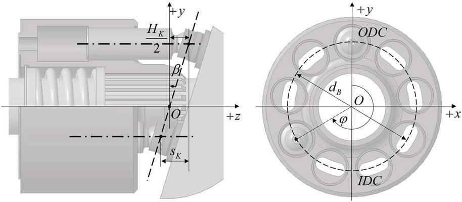
Figure 1 Kinematic convention.
The maximum stroke of each piston inside the cylinder of the block depends on the inclination of the swashplate as well as the pitch radius of the block and is defined as:
| (1) |
The piston displacement () in general also varies with the angular position of the piston .
| (2) |
Assuming the shaft angular speed as , the piston sliding velocity can be derived as:
| (3) |
The physical forces acting within the interface for the kinematic convention considered in the model is explained in detail by Ivantysyn and Ivantysynova [10]. The external loads must be hydrodynamically balanced by the pressure developed in the piston/cylinder lubricating film. The dynamic fluid film geometry directly affects the deformations of the solid bodies as well as the squeeze motion during operation. Therefore, it is important to accurately define and calculate the fluid film geometry. The fluid film definition and thickness evaluations based on the eccentric position of the piston within the cylinder bore as developed by Wieczorek and Ivantysynova [11] is used in this study as demonstrated in Figure 2.
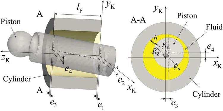
Figure 2 Instantaneous eccentric position of piston inside the bore [2].
The eccentricity of the piston with respect to the coordinate system as defined in Figure 2 can be written as:
| (4) | ||
| (5) |
3 Fluid Structure and Thermal Interaction Model
The non-isothermal fluid structure interaction model is used to analyse the different geometric shapes resulting from manufacturing inaccuracies and their effect on the performance of the interface. The piston/cylinder interface model continually developed by Pelosi [2], Mizell [12] and Shang [13] is used to model the behaviour of the interface over a full shaft revolution. Figure 3 shows a representative block diagram of the model used for the study. The model used in the study is briefly summarized in this section but is not the novelty of the paper. The detailed modeling approach is well explained in the above references.

Figure 3 Fully coupled multiphysics model.
For every time step, the lubricating film thickness in the piston/cylinder interface is updated along with the fluid properties. In this model, the fluid film behavior is solved within a finite volume grid where the pressure and temperature distribution in the fluid film are described by the Reynolds and energy equation respectively. The force balance loop takes into consideration the external forces acting on the piston, the forces due to fluid pressure field in the interface as well as the forces due to predicted contact between the piston and the bore. Based on the residual force, the required squeeze is evaluated by integrating the acceleration.
The elastic deformations due to the resultant pressure distribution in the gap as well as other pressures namely the pressures in the neighboring gaps and the case pressures are considered. The resultant solid body deformations due to all the pressure fields are evaluated using the influence method, where a set of influence matrices for the solid bodies are generated using a separate finite element analysis. This approach is discussed by Ivantysynova and Huang [14]. Once the required squeeze for balancing all the external forces has been determined, the model proceeds to the next time step, until the thermal convergence is achieved. The net energy dissipation in the fluid film is computed from the viscous energy dissipation function, .
| (6) |
Where, is the radius of the piston and L is the gap length.
One of the other major sources for the energy dissipation is the leakage from the displacement chamber through the interface into the case. The net leakage flow at each shaft angle is evaluated by integration of the axial velocity over the film thickness (h) and over the circumference () [3].
| (7) |
In the current modelling approach a full film lubrication is assumed at all instants and therefore, a correction contact stress is calculated where the fluid film pressure forces are not enough to balance the external forces. The correction stress is linearly proportional to the difference between the local film thickness and the minimum specified film thickness.
| (8) |
The model imposes a stress on the elements of the fluid mesh where the film thickness drops below (0.1 micrometers). The choice of proportionality constant is chosen to be as:
| (9) |
Where, is the equivalent Young’s modulus of the materials used for the piston and the bushing in the interface and is defined as:
| (10) |
The correction forces are obtained by integrating the stress fields and are directly considered in the force balance loop. However, the model does not consider the energy dissipation due to contact friction or mixed friction, therefore, a separate metric of energy dissipation due to contact friction () is established based on the contact stress () and the total piston velocity to quantify these effects.
| (11) |
The metric is defined as an average over one complete shaft revolution. It establishes a correlation of energy dissipation due to contact friction with the contact stress. For observing the relative trends among different interface designs for a given operating condition, this co-efficient of friction is assumed to be unit. However, the friction coefficient () in actual will always be less and will need to be investigated for different possible circumstances but is beyond the scope of this paper.
4 Simulation Study and Analyses
A simulation study is performed considering a reference 75 cm pump design using the above discussed model to study different part geometric shapes for three different operating conditions summarized in the Table 1.
Table 1 Operating conditions
| Operating conditions | OC1 | OC2 | OC3 |
| High pressure [bar] | 475 | 325 | 325 |
| Low Pressure [bar] | 25 | 25 | 25 |
| Angular Speed [rpm] | 3600 | 2000 | 2000 |
| Displacement [%] | 100 | 100 | 20 |
Table 2 Material properties of solid parts
| Material Property | Pistons | Cylinder Block | Bushings |
| Elastic Modulus [GPa] | 210 | 210 | 110 |
| Poisson’s ratio [] | 0.27 | 0.27 | 0.31 |
As shown, a frequently occurring operating condition, a high pressure-high speed operating condition and a partial displacement operating condition have been chosen to investigate the effect of the part geometry shapes. The cylinder block and the pistons are made of steel while the bushings are made of brass whose material properties are summarized in the following Figure 4 shows the reference geometry and geometric parameters defining the piston/cylinder lubricating interface.
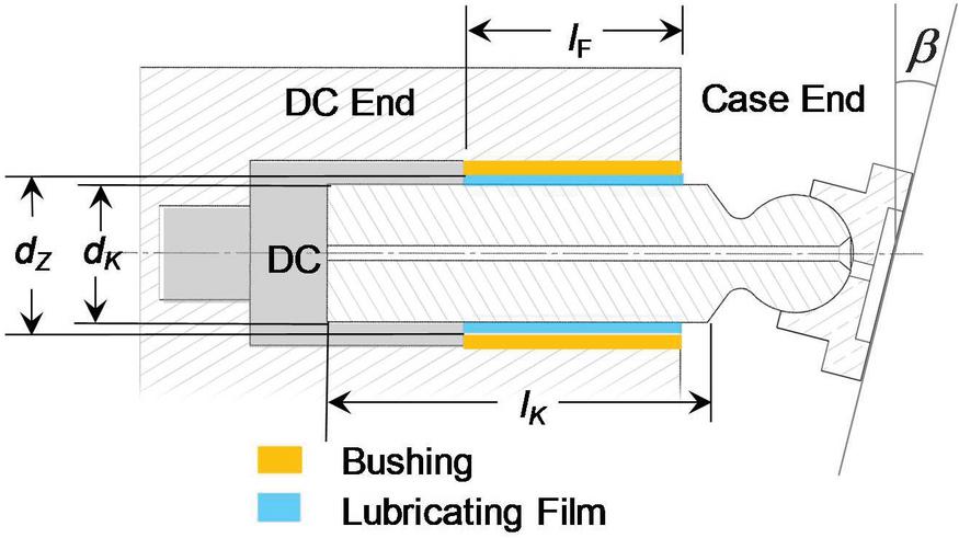
Figure 4 Piston/cylinder interface geometry parameters.
In the ideal case, the piston and the cylinder bore surfaces are perfectly cylindrical. However, the solid parts forming the interface has manufacturing tolerances such as the true size, perpendicularity and parallelism. These manufacturing tolerances are of the order of the film thickness in the lubricating film. Therefore, it is highly critical to analyse the effect of the resulting manufacturing shape deviations and define relative effect of the resulting film geometry on the performance of the interface. Performance parameters ( and ) are evaluated using Equations (6) and (11) for different extent of the different manufacturing deviations and are compared to the reference baseline simulation for different operating conditions. The baseline simulation assumes perfectly cylindrical piston and cylinder at the nominal prescribed clearance for the reference unit. Four different manufacturing shape deviations are analysed and discussed in the following sections. An exemplary tolerance limit is marked on each of the performance variation plots.
4.1 Clearance
Any deviation from the nominal dimension of either the piston or the bore would directly affect the clearance and finally, the lubricating fluid film thickness and shape. The nominal clearance for a piston/cylinder interface is defined as the difference between the diameter of the cylinder bore () and the diameter of the piston (). This clearance directly affects the fluid film thickness and hence, is very critical for the performance of the interface. Also, technological advancements in manufacturing processes have allowed reducing of the nominal clearances between the solid bodies for an energy efficient operation of the pump. The following Figure 5 highlights the variation in net energy dissipation () with varying normalized clearances for one piston/cylinder interface. A normalized clearance of 1 refers to the baseline clearance of the reference unit.
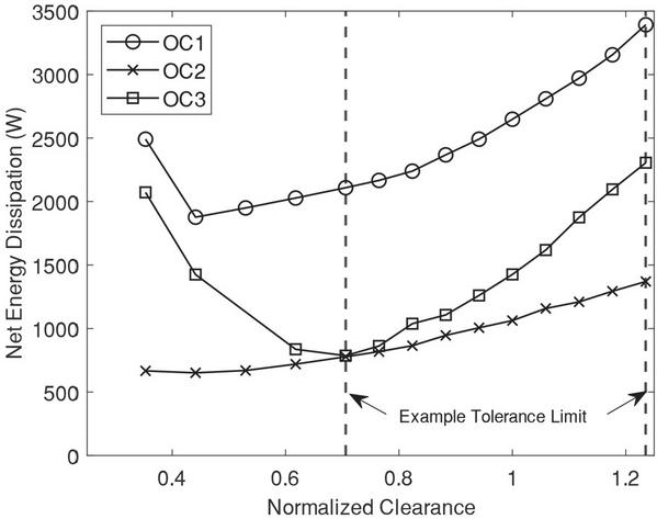
Figure 5 Variation of energy dissipation with clearance.
As seen from the results, for all operating conditions, the energy dissipation from the interface increases as the clearance is increased from the nominal. This is because, at higher clearances, the average fluid film thickness increases and causes more leakage from the interface. On the other hand, as the clearance decreases, the energy dissipation is seen to decrease as the clearance is decreased but then later increases with further decrease in clearance. Additional reduction in clearance is studied to highlight this effect. This limitation in reduction of energy dissipation with reducing the clearance is because at very low clearances the viscous shear effects dominate a lot and cause the net energy dissipation to increase beyond the reduction achieved through leakage reduction.
Moreover, at very low clearances, the tendency of the fluid film to collapse and cause metal to metal contact is also high. This can be visualized by looking at the variation in the energy dissipation due to contact with the normalized clearance for the operating conditions OC1 and OC2 described in Figure 6.
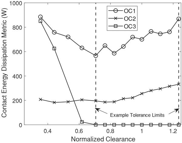
Figure 6 Contact energy dissipation variation with clearance.
4.2 Piston Taper
Even at the same nominal clearance, manufacturing tapers on solid parts can change the fluid film characteristics although the average lubricating film clearance is the same. The simulation study analyses the effect of different resulting tapers on the piston surface. The following Figure 7 shows an exaggerated representation of the taper on the piston along with the characteristic parameters.

Figure 7 Piston taper characterization.
In the simulation study, the average clearance is kept constant, and the taper of the piston surface (m) is varied. The following Figure 8 shows the variation of energy dissipation () with varying slope of piston taper () defined in microns per millimeter.
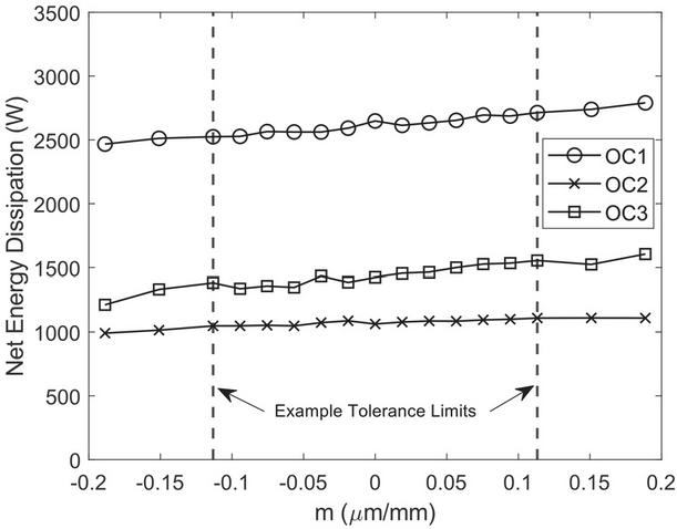
Figure 8 Energy dissipation variation with piston taper.
The variation in the energy dissipation due to taper is within 15% of the baseline for the tapers studied. The extent of variation is primarily limited because the length of the piston is almost 1.8 times the lubricating film length. Therefore, the piston taper has less effect on the fluid film characteristics and the net energy dissipation as compared to clearance. Moreover, the positive taper is detrimental to the energy efficiency of the interface while the negative taper helps to reduce the energy dissipation. This can be attributed to the fact that the piston with a negative taper will provide relatively higher resistance for the leakage into the case of the pump as compared to the positive tapered. However, it is also important to look at energy dissipation due to contact metric and its variation with the piston taper is shown in Figure 9.
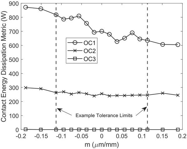
Figure 9 Contact energy dissipation variation with piston taper.
Although negative taper reduces the net leakage from the interface, but it is also more prone to contact at the case end thus, increasing the contact energy dissipation metric. Therefore, the net effect of taper on the piston is almost negligible in terms of energy dissipations from the interface.
4.3 Cylinder Bore Taper
The simulation study analyses the effect of different resulting tapers on the inner bore surface of the bushing. In the simulation study, the average clearance is kept constant and the slope of the taper of the bore surface (m’) is varied. It is important to note that the taper deviation is on micrometers scale and is exaggerated in the Figure 10 for better illustration.
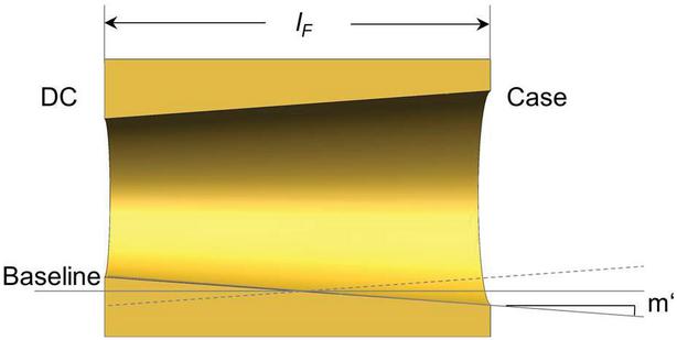
Figure 10 Cylinder bore taper characterization.
The above representation shows a negative tapered bushing. The following Figure 11 shows the variation of energy dissipation () with variation of slope of the taper () on the bottom bore surface defined in microns per millimeter.
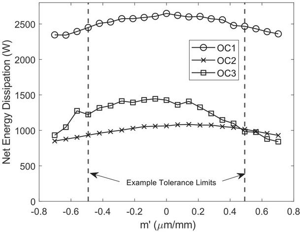
Figure 11 Energy dissipation variation with cylinder bore taper.
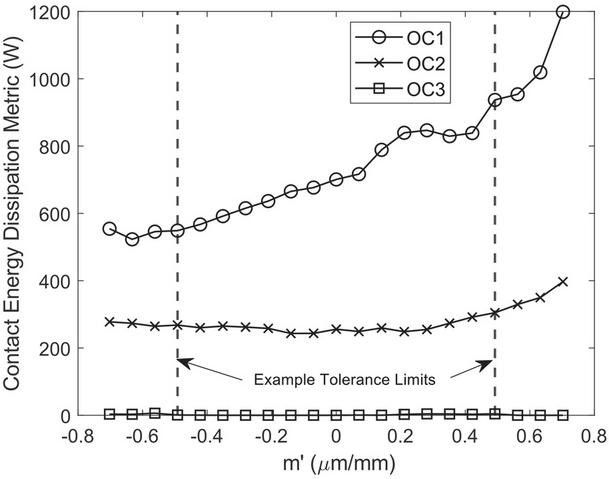
Figure 12 Contact energy dissipation variation with cylinder bore taper.
The variation of energy dissipation is considerable in case of OC3 but is very limited for operating conditions OC1 and OC2. This reduction in energy dissipation is primarily due to net reduction in leakage from the interface. However, it is also important to look at energy dissipation and its variation with the bore taper is shown in Figure 12.
Although the positive taper also reduces the net energy dissipation, but the reduced localized film thickness near the case end will result in more contact friction. The reduction in leakage is mostly because of the inherent resistance the taper offers to the leakage flow to the case. On the other hand, a negative taper will give the piston more scope to tilt near the low-pressure case end. This not only better seals the interface but also reduces chances of any metal to metal contact. This phenomenon is also observed by Busquets [1] on the surface shaping of the bore. Therefore, having a negative taper on the bore bushing surface will in turn help improve the net performance of the interface.
4.4 Roundness of the Bore
Roundness error is a measure of how closely the shape of the object approaches that if the prescribed nominal circle. Although, there are a lot of possible permutations of roundness errors of the cylinder bore, this study limits itself to study of elliptic roundness. Elliptic roundness is commonly seen after finishing processes of circular parts.
To avoid any effects of clearance variation, it is ensured that the sum of the major axes of the ellipse is equal to two times the nominal diameter of the bore. The deviation of the axes along the X axis from the nominal shape () in micrometers is varied in the simulation study. The deviation is assumed to be only circumferential and is symmetric along the bushing length. The following Figure 13 shows a representation of the roundness error of the cylinder bore and the convention used in this study.
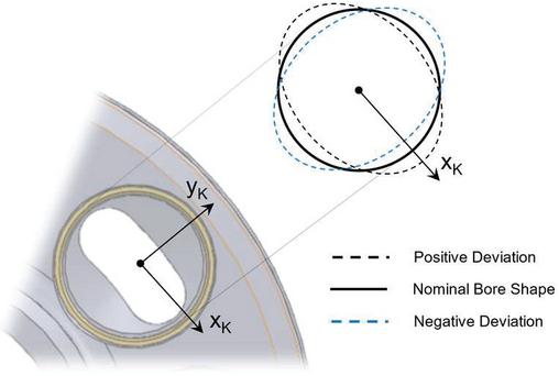
Figure 13 Bore roundness characterization.
The following Figure 14 shows the variation of energy dissipation with variation of roundness of the bore. It is important to note that a positive deviation along the X-axis in the scope of our study implies that the profile has a negative deviation from the nominal shape along the Y-axis.
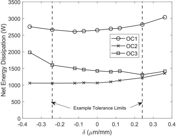
Figure 14 Energy dissipation variation with elliptic bore roundness.
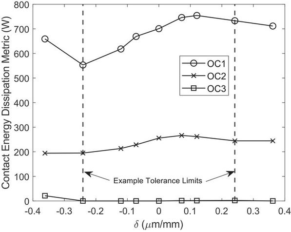
Figure 15 Contact energy dissipation variation with roundness of the bore.
In general, the elliptic roundness error is mostly detrimental to the energy efficiency of the interface. However, the energy dissipation does not change much with small magnitude of roundness error. The following Figure 15 shows the variation of the contact energy dissipation metric () with respect to the deviation (). It can be seen that an elliptic roundness error with negative deviation as defined in Figure 13 ensures the piston is able to tilt more as the effect of the piston side force preventing metal to metal contact at the either ends of the lubricating film. However, a minor axis along Y-axis (Positive Deviation in Figure 13) not only increases the contact but also allows more leakage thus increasing the net energy dissipation.
5 Conclusions
The presented paper analysed the effect of different solid part geometries resulting from commonly observed manufacturing inaccuracies on the performance of the piston/cylinder interface of an axial piston machine. Different manufacturing inaccuracies resulting in change in nominal dimension of the solid parts, tapering of the solid part/s and roundness of the bore are analysed in an independent extensive simulation study using the model developed by the authors’ team. A separate metric for quantifying the relative extent of energy dissipation due to contact friction is established to supplement the capabilities of the model.
The performance of each of the resulting piston/cylinder interface configuration incorporating the above-mentioned inaccuracies are compared to the ideal baseline configuration for three different operating conditions. The energy dissipation from the interface is highly dependent on the clearance between the solid parts which directly governs the average lubricating film thickness in the interface. Energy dissipation increases if we increase the clearance, decreases when we decrease the clearance only up to a certain reduced clearance. At very low clearances, viscous shear effect dominates and significantly affect the net energy dissipation from the interface. The variation in the energy dissipation due to taper on the piston is limited and within 15% of the baseline energy dissipation. Although negative taper reduces the net energy dissipation by reducing leakage but is also more prone to metal-to-metal friction and therefore, altogether taper has very less effect on the energy dissipation of the interface. The bushing taper on either direction helps in reducing the energy dissipation predominantly by reducing the net leakage from the interface. However, looking at the energy dissipation due to contact friction, only the positive taper on the cylinder bore will help in better operation of the interface. The elliptic roundness error on the cylinder bore is always detrimental to the net energy dissipation of the interface beyond a certain deviation and therefore, needs to be limited by a prescribed tolerance.
References
[1] Stefan Gels and Hubertus Murrenhoff (2010), “Simulation of the Lubricating Film between Contoured Piston and Cylinder”, International Journal of Fluid Power, 11:2, 15–24, DOI: 10.1080/14399776.2010.10781003.
[2] Pelosi, M. and Ivantysynova, M., “A Novel Fluid-Structure Interaction Model for Lubricating Gaps of Piston Machines”, Proc. of the 5th Fluid Structure Interaction Conference, Crete, pp. 13–24, 2009.
[3] Manring, N. D. (September 1, 1999), “Friction Forces Within the Cylinder Bores of Swash-Plate Type Axial-Piston Pumps and Motors”, ASME, J. Dyn. Sys., Meas., Control. September 1999; 121(3): 531–537. https://doi.org/10.1115/1.2802507.
[4] Xu, B., Zhang, J., Yang, H. et al. Investigation on the radial micro-motion about piston of axial piston pump. Chin. J. Mech. Eng. 26, 325–333 (2013).
[5] Hasko, D., Shang, L., Noppe, E., Lefrançois, E, Virtual Assessment and Experimental Validation of Power Loss Contributions in Swash Plate Type Axial Piston Pumps. Energies 2019, 12, 3096.
[6] Chacon, R.; Ivantysynova, M. Virtual Prototyping of Axial Piston Machines: Numerical Method and Experimental Validation. Energies 2019, 12, 1674.
[7] Yamaguchi, A. Motion of Pistons in Piston-Type Hydraulic Machines. Bulletin of JSME, Vol. 19, No. 130, pp. 402–419, 1976.
[8] K. Sadashivappa, M. Singaperumal, K. Narayanasamy, On the efficiency of the axial piston motor considering piston form deviations, Mechatronics, Volume 6, Issue 3, 1996, Pages 283–301, ISSN 0957-4158, https://doi.org/10.1016/0957-4158(95)00074-7.
[9] Fnu Rituraj, Andrea Vacca, Mario Antonio Morselli, Modeling of manufacturing errors in external gear machines and experimental validation, Mechanism and Machine Theory, Volume 140, 2019, Pages 457–478, ISSN 0094-114X.
[10] Ivantysyn, J. and Ivantysynova, M., Hydrostatic Pumps and Motors, Principles, Designs, Performance, Modelling, Analysis, Control and Testing. New Delhi. Academia Books International, ISBN -81-85522-16-2, 2001.
[11] Wieczorek, U. and Ivantysynova, M., Computer Aided Optimization of Bearing and Sealing Gaps in Hydrostatic Machines – The Simulation Tool CASPAR. International Journal of Fluid Power, Vol. 3 (2002), No. 1, pp. 7–20, 2002.
[12] D. Mizell, “A Study of the Piston Cylinder Interface of Axial Piston Machines”, PhD dissertation, School of Mechanical Engineering, Purdue University, West Lafayette, IN, 2016.
[13] L. Shang, “A Path Toward an Effective Scaling Approach for Axial Piston Machine,” PhD dissertation, Agricultural and Biological Engineering, Purdue University, West Lafayette, IN, 2018.
[14] Ivantysynova, M. and Huang, Ch., Investigation of the gap flow in displacement machines considering the elastohydrodynamic effect, 5th JFPS International Symposium on Fluid Power. Nara, Japan. pp. 219–229, 2002.
Biographies

Shanmukh Sarode received his bachelor’s degree (B.Tech) in Mechanical Engineering from Sardar Vallabhbhai National Institute of Technology, Surat in 2017. He joined Maha Fluid Power Research Center, Purdue University in 2017 and is currently a PhD candidate in the School of Mechanical Engineering at Purdue. His research areas include modelling of hydrostatic and hydrodynamic pumps, electrohydraulic system design, and electrification.

Lizhi Shang received his B.S. from Huazhong University of science and technology in 2011 and his M.S from New Jersey Institute of Technology in 2013. He joined the Maha Fluid Power Research Center in 2013 and graduated with a PhD degree from Purdue University in 2018 with late Prof. Monika Ivantysynova as his advisor. Dr. Shang joined the Maha Fluid Power Research Center as an assistant professor in 2020. His research interests focus on designing and modelling hydrostatic pumps and motors, hydrodynamic pumps and turbines, fluid power systems, and advanced computational and experimental tribological analysis.

Andrea Vacca is the Maha Fluid Power Faculty Chair and a Professor at Purdue University. He currently leads the Maha Fluid Power Research Center which was established in 2004 by the late Prof. Monika Ivantysynova. Dr. Vacca completed his studies in Italy (Ph.D. from the University of Florence in 2005), and he joined Purdue University in 2010 after being an Assistant Professor at the University of Parma (Italy). Fluid power technology has been Dr. Vacca’s major research interest since 2002. Dr. Vacca authored the textbook “Hydraulic Fluid Power” by Wiley and more than 150 technical papers, most of them published in international journals or referred conferences. He is chair of Fluid Power Systems and Technology Division (FPST) of the American Society of Mechanical Engineers (ASME), and a former chair of the Fluid Power Division of the Society of Automotive Engineers (SAE). Dr. Vacca is also one of the Directors of the Global Fluid Power Society (GFPS). Furthermore, he is also the Editor in Chief of the International Journal of Fluid Power. Dr. Vacca also received the 2019 J. Braham medal of the Institution of the Mechanical Engineers (IMechE).
International Journal of Fluid Power, Vol. 23_3, 343–362.
doi: 10.13052/ijfp1439-9776.2334
© 2022 River Publishers