Thermal Coupling Simulation of Electro-Hydrostatic Actuator Subjected to Critical Temperature Conditions
Xu Han1,*, Tatiana Minav2, Mingkang Wang1, Yongling Fu1 and Matti Pietola3
1School of Mechanical Engineering and Automation, Beihang University, Beijing, China
2Faculty of Engineering and Natural Sciences, Tampere University, Tampere, Finland
3Department of Mechanical Engineering School of Engineering, Aalto University, Espoo, Finland
E-mail: thanxu@buaa.edu.cn; tatiana.minav@tuni.fi; wmk_buaa@sina.com; fuyongling@buaa.edu.cn; matti.pietola@aalto.fi
*Corresponding Author
Received 09 June 2022; Accepted 21 July 2022; Publication 12 September 2022
Abstract
Electro-hydrostatic actuators (EHAs) are emerging transmission techniques originated from aerospace industry and being introduced to various application fields, such as ships, robots, construction machines, and machine tools. Despite the advantages of high efficiency, easy maintenance, electrified power, etc., EHAs are usually self-contained integrated devices, resulting in low heat dissipation ability. Therefore, thermal coupling models are necessary for the evaluation of each design option during the EHA development. In this paper, a thermal coupling model was established for EHA thermal characteristic analysis during the detail design stage. The disciplines of electrics, mechanics, system level hydraulics, losses, and control are implemented by lumped parameter modeling while the disciplines of thermodynamics and fluid dynamics are simulated by computational fluid dynamics (CFD). Subsequently, a simulation analysis focusing on the critical temperature conditions was conducted, and the dynamic thermal and power responses were achieved. The simulation results are applicable to gain confidence for EHA detail design work as well as proved the functions of the proposed model as a practical development tool.
Keywords: Electro-hydrostatic actuator, thermal coupling, modeling and simulation, computational fluid dynamics.
1 Introduction
Electrification trend contributes from both economic and environmental points of view to machinery in various industry fields. With respect to the subsystem of heavy-duty actuation, electro-hydrostatic actuators (EHAs) are a considerable option over conventional hydraulic actuation due to its advantages such as electrified power feature as well as the compactness, easy maintenance, high efficiency, etc. Conversely, the high integrated self-contained structure of the EHA leads to a highly multi-physics coupling nature and the deficiency of heat dissipation, which requires delicate characteristic analysis during the EHA design. Thermal coupling simulation models are effective tools to achieve aforementioned purposes.
Most existing contributions regarding the EHA thermal coupling modeling are within 0D/1D models, which are primarily aiding preliminary system level simulation and analysis [1]. 3D fluid-thermal coupling models of EHAs have been developed, whereas the dynamic characteristics modules are not integrated [2, 3]. However, EHA is a power-on-demand actuator and the design evaluation must be implemented based on duty cycles which calls for transient simulation. Therefore, a dynamic EHA model equipped with 3D thermal coupling module should be developed for the EHA detail design stage and subsequent virtual testing tasks [4]. The bondgraph analysis together with FEM model is an attempt for this objective, but the 3D thermal module does not involve the fluid volume, which leaves the fluid temperature without accurate evaluation [5].
In this paper, a thermal coupling model of EHA was developed through updating the existing 0D/1D dynamic models with a 3D thermal module. The 3D thermal module is utilized only for heat transfer calculation and temperature prediction based on 3D computational fluid dynamics (CFD) method. This model combines the advantages of fast simulation and elaborate temperature evaluation. Thus, it is suitable to be used in the EHA detail design stage as an analysis and virtual testing tool.
The paper is organized as follows: the selected EHA case is presented in Section 2. in Section 3, the model architecture and the model implementation is illustrated in detail. Section 4 presents the simulation study under critical temperature conditions. The temperature and the power related results were analyzed. The conclusion is drawn is Section 5.
2 EHA Description
A turreted gun is usually designed with two degrees of freedom (DOF) for aiming the target, horizontal and vertical. The heavy artillery mostly utilizes the hydraulic actuator for controlling its vertical motion. But the conventional hydraulic actuator is implemented with an individual power unit and jumbled pipes although only one cylinder is needed to be powered. Furthermore, the low efficiency results in huge heat dissipation that deteriorates the working conditions of the operators. Therefore, an EHA for controlling the vertical motion of the artillery was developed to tackle the aforementioned issues induced by the conventional hydraulic actuators as well as advance the electrification progress.
Table 1 Partial specifications of the EHA
| Stroke | 171 mm |
| Maximum force | 12 kN |
| Maximum velocity | 300 mm/s |
| Lowest velocity | 0.1 mm/s |
| Bandwidth | 8Hz |
| Maximum motor speed | 12500 rpm |
| Power voltage | 270 VDC |
| Nominal hydraulic pressure | 11 MPa |
Partial specifications of the developed EHA is displayed in Table 1. The EHA is modularly designed that consists of a symmetric cylinder, the manifold and the motor-pump-reservoir unit, as displayed in Figure 1. The piston pump and the servo motor share a mutual shell, which is fully filled with the pump drainage oil after assembling. The EHA was designed to resist a high recoil load of 8 times nominal output force. Once the gun is on standby, the EHA will continuously receive orders from the fire control system and actuate the gun to the desired elevation angle.
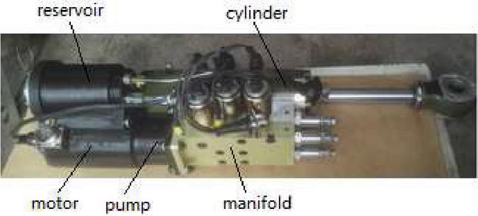
Figure 1 An EHA subjected to the vertical motion control of a turreted gun.
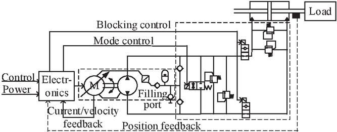
Figure 2 Schematic of the turreted gun EHA.
The schematics of the EHA is illustrated in Figure 2. The motor-pump unit operates in velocity control mode with an inner current control loop. Then the flow rate and direction of the EHA is subject to the motor-pump rotational speed. The drainage flow of the pump is collected in the reservoir, which will again recharge to the pump ports according to the individual pressure level. The manifold implements the functions of bypass/active mode control, high pressure relief and cylinder blocking under high recoil situation. The outer position loop control is optional, which depends on the command from the fire control system.
3 Thermal Coupling Modeling of EHA
The 0D/1D models have been proven to be adequate for EHA performance prediction when neglecting the thermal coupling effects [6]. However, the thermally affected performance and the temperature distribution itself need to be addressed when developing a practical EHA, which can be realized by 3D thermal model rather than lumped parameter thermal model. Therefore, adding variable ports on the 0D/1D models to interact with a 3D thermal model specialized for temperature simulation is an applicable solution to combine efficiency and accuracy advantages [4].
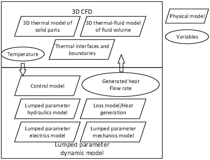
Figure 3 Model architecture.
The model architecture is shown in Figure 3. The model is divided into the CFD model part and the lumped parameter model part. Besides the common equations adopted by the EHA 0D/1D models, the lumped parameter model added loss models for heat generation calculation, which are utilized as boundary conditions of the CFD model. The temperature dependent parameters are also linked with the temperature variables output from the CFD model for establishing the thermal coupling mechanism. The dynamics of the hydraulic transmission is modeled in the lumped parameter model since the accuracy is adequate for EHA performance evaluation while CFD simulating of the complete EHA fluid transmission would cost too high computation resources.
The CFD model utilizes energy equation to evaluate the thermal activities of the solid parts of EHA while the momentum and continuity equations are adjoined for the fluid part simulation. The fluid part of the CFD model just use the flow results from the lumped parameter model to define the boundaries of the fluid volume, which can reduce the calculation cost compared with mimicking the complete flow mechanism itself. The precision under this simplification is acceptable since the CFD model is used only for temperature prediction.
3.1 Basic Physical Models
The continuity, momentum and energy equations are utilized for modeling the fluid part of the EHA in CFD model, as in (1–4). For the solid part modeling, only energy equation is needed.
| (1) | |
| (2) | |
| (3) | |
| (4) |
where is the density of the fluid, is the velocity vector of the flow or mass, is the static pressure, is the stress tensor, is the acceleration of gravity, h is the sensible enthalpy, v is the velocity magnitude of the flow, and k is the conductivity.
The geometry of the exemplified EHA was imported into CFD simulation environment and was meshed into 1.74 million elements. The outer shell of the EHA transfers heat with the environment in convection of 16.7 W/m/C. Three significant volumes exist in an EHA, two cylinder chambers and one reservoir volume (including the volume inside the motor-pump shell). The flow boundaries of these volumes are defined with the instant simulation results of the lumped parameter EHA model. Moreover, the heat source was assigned on the regarding surfaces of the CFD model with values from the lumped parameter loss model.
Many validated lumped parameter EHA models have been developed [7]. However, the temperature dependent features and the loss models are still to be implemented. The temperature dependence of the torque constant and winding resistance of the motor is demonstrated in (5–6).
| (5) | ||
| (6) |
where is the torque constant at reference temperature, is the corrective coefficient on torque constant, T is the instant temperature, is the reference temperature, is the winding resistance at reference temperature, and is the corrective coefficient on winding resistance. The temperature dependent absolute viscosity of the fluid is modeled as in (7).
| (7) |
where is the fluid absolute viscosity at reference temperature and is the corrective coefficient on the absolute viscosity. The leakages of the hydraulics are modeled with (8–9) for each leakage point.
| (8) | |
| (9) |
where is the highest flow coefficient, is the flow number at which transfer between laminar and turbulent, A is the effective flow area, is the fluid density, and is the pressure difference on the leakage point. The , , and A are constant parameters, which were identified from the leakage data of each leakage point. So the leakage is coupled with the instant temperature by the fluid viscosity variance.
The energy losses of the EHA formulate the heat load of the heat transfer process. The friction loss is modeled as viscous friction since all moving pairs of the EHA are in the hydraulic oil. The copper and friction losses are considered for the electric motor as demonstrated in (10–11).
| (10) | |
| (11) |
where i is the current in the winding, is the rotational speed of the motor, and is the coefficient of the motor viscous friction. The volumetric and mechanical losses of the pump are modeled as in (12–13).
| (12) | |
| (13) |
where , are the inner leakage and drainage of the pump, is the rotational speed of the pump, and is the coefficient of the pump viscous friction. The loss of the cylinder together with the manifold are modeled as leakage and friction in (14–15).
| (14) | |
| (15) |
where , are the leakage of the cylinder and the manifold, is the translational velocity of the cylinder, and is the coefficient of the cylinder viscous friction. The , , and are parameters identified based on the performance data of the motor, pump and cylinder.
4 Simulation Results
The proposed model in Section 3 was implemented on the turreted gun EHA. The simulation was carried out with the thermal critical scenario, holding of the full load within an high ambient temperature [8]. A low ambient temperature scenario was also simulated for addressing the wide range ambient temperature effects. The two scenarios are concluded as:
• the EHA working in a load hold condition with 12 kN force at the midpoint of the cylinder; the ambient temperature is constant 40C, the initial temperature of the fluid is 40C;
• the EHA working in a load hold condition with 12 kN force at the midpoint of the cylinder; the ambient temperature is constant 0C, the initial temperature of the fluid is 40C.
Both scenarios were simulated for 600 seconds, which is enough long to reach a final stable state. Main variables were summarized in Table 2, which indicates the significant influence by the temperature and thermal coupling. For either scenario, the initial leakage was lower than the final ones since the final temperature of the leakage inlet (the inlet port when considering the pump) was higher and resulted in lower viscosity. The fluid viscosity decrease additionally leads to lower heat generated by the motor and pump due to the viscous friction decreasing. Although the leakage increased, it’s the friction losses dominating the overall loss level since the hydraulic components are relatively high volumetric efficiency models.
By comparing different scenarios, it can be seen that the initial losses of the motor-pump at 40C temperature is identical as the final losses at 0C temperature. This can be explained due to the final leakage inlet temperature of the motor-pump unit under 0C scenario is 40C, which is same as the initial conditions of the 40C scenario (as shown in Figures 4 and 5). Accordingly, the final state of the 40C scenario arrived at a higher temperature level compared to the 0C scenario. Therefore, the final drainage flow of the 40C scenario is the highest among all the EHA states during the simulation while the losses are the lowest since the fluid viscosity arrived at the lowest.
Table 2 Variable values at different simulation time
| Heat Generated (W) | ||||
| EHA States | Motor | Pump | Cylinder | Drainage Flow (L/min) |
| Initial of 0C | 291 | 101 | 2.4 | 0.34 |
| Final of 0C | 122 | 65 | 4.6 | 0.48 |
| Initial of 40C | 122 | 65 | 1.8 | 0.48 |
| Final of 40C | 57 | 45 | 4.1 | 0.58 |
The evolving process and the temperature distribution of each scenario are illustrated in Figures 4 and 5 respectively. In the first 100 seconds the EHA temperature changed significantly due to the initial stable state was disturbed and the fluid started circulating. Then the fluid was gradually heated and the viscosity decreased. During this period, the overall generated heat decreased due to the reduction of the viscous friction, the convection between the fluid and the solid strengthened due to the increase of the flow rate, and the convection between the EHA and the environment strengthened due to higher temperature difference. After the first 100 seconds the EHA approximated the final stable state and continued a slower evolution.
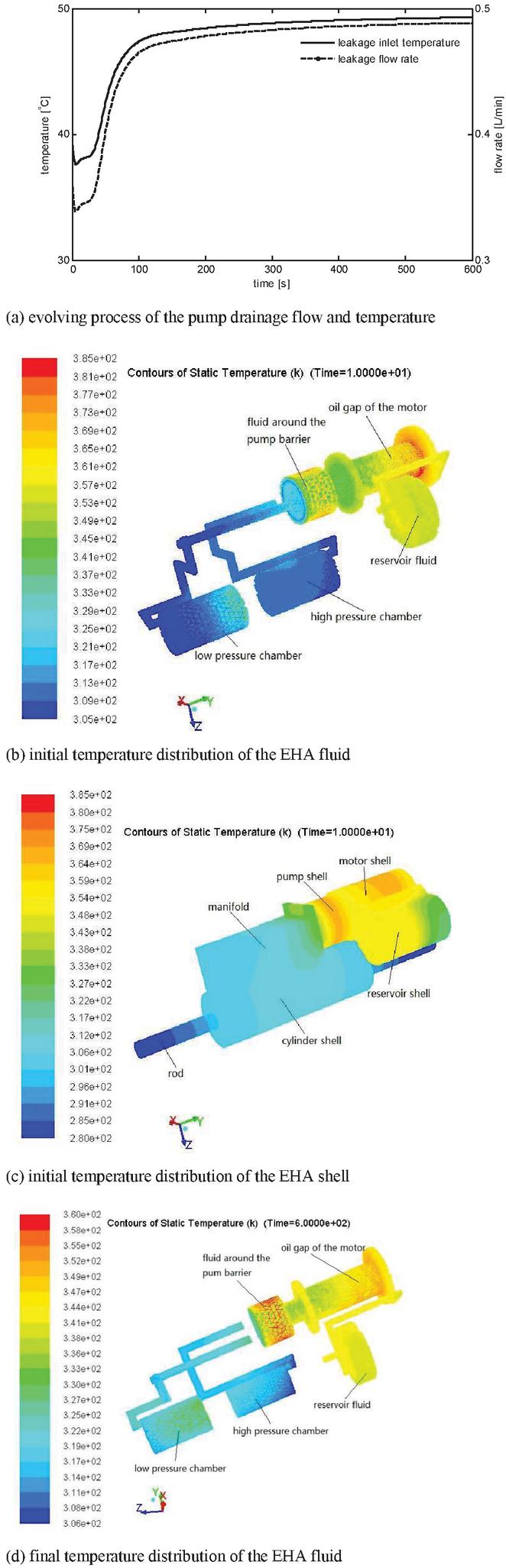
Figure 4 Simulation results under 0C ambient temperature.
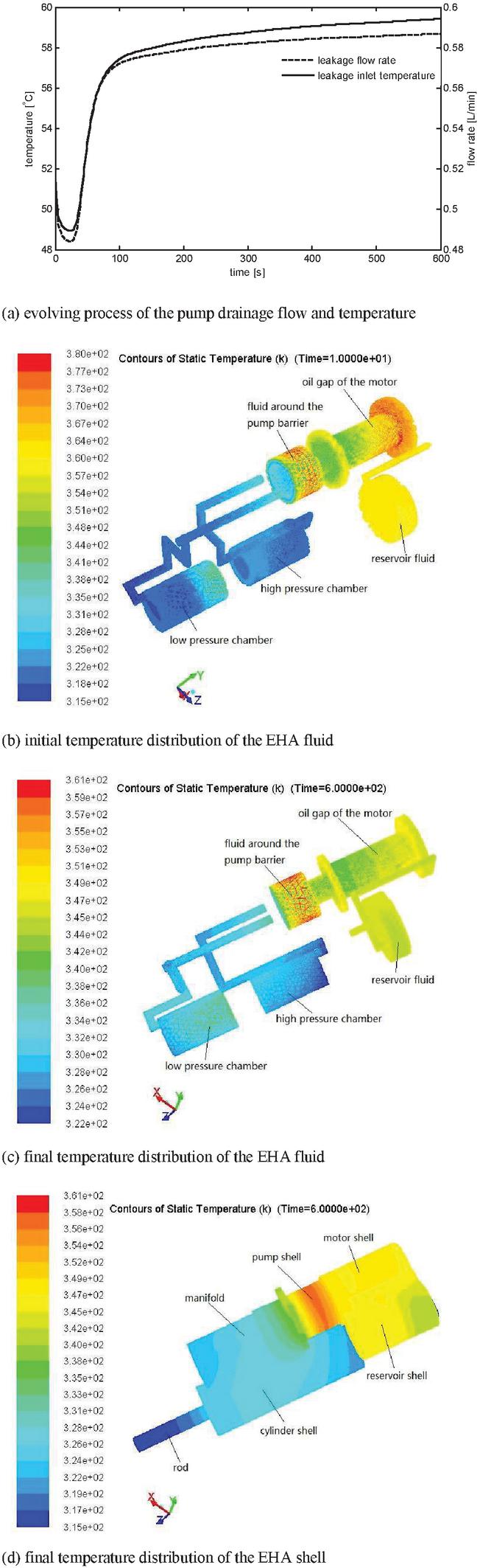
Figure 5 Simulation results under 40C ambient temperature.
The hottest domain of the EHA was the fluid around the pump barrier while the fluid in the rear motor shell sometimes also experienced the highest temperature. The average temperature of the motor-pump-reservoir fluid was 72C at the initial of the 0C scenario, 64C at the final of the 0C scenario, 76C at the initial of the 40C scenario, and 68C at the final of the 0C scenario. Although the average temperature appeared no major difference, the local temperature differed significantly among the four picked contour results, which may fail to be captured in the 0D/1D thermal model.
For both scenarios, the final temperature of the motor-pump-reservoir fluid decreased during the simulation period while the chamber fluid appeared an inverse process. This indicated that the internal fluid circulation of the EHA can equilibrate the temperature field which improve the durability of the EHA against load holding conditions. Meanwhile, it also alerts that a sudden over load may induce a local over-heated which is harmful for an EHA. Both scenarios evolved towards better temperature distribution field thanks to the stronger convection effects, viscous friction reduction and the high volumetric efficiency which prevent a soar of leakage losses.
The two scenarios arrived at almost the same highest temperature since the generated heat of the EHA under high ambient temperature is lower so that the required temperature difference between the EHA and the environment is lower to attain a thermal balance. For the initial thermal response, the 0C scenario showed more dangerous results because a higher local fluid temperature appeared to be at 112C. Therefore, it is worth noting that, apart from the environment and the duty cycles, the initial conditions can also strongly influence the evolving of the thermal process. The different initial fluid temperature may result in totally different temperature distribution and variation of the EHA due to its highly nonlinear and coupled nature. That’s one of the reasons why the EHA may employ a heating device especially when it may be started in a very low initial temperature.
5 Conclusion
A thermal coupling EHA model combining lumped parameter modeling and CFD method was proposed for characteristic analysis during the detail design stage. The 3D thermal module enhanced the temperature evaluation accuracy while the lumped parameter module maintained the efficiency advantage. The model is easy to be implemented and employed into a modular modeling environment. These advantages prompt the model to be more considerable than the existing 0D/1D models and individual 3D thermal model.
The simulation results revealed the elaborate EHA characteristics that can be gained with the proposed model. The dynamic responses of an exemplified EHA under the thermal critical duty cycle were achieved. Both 0C and 40C ambient temperature were analyzed. Either scenario showed the complete evolving process of the EHA from an initial state to the corresponding stable state. Local hot points were identified which are not accessible relying on the 0D/1D models. The thermal coupling mechanism and its significant influence are presented in an explicit way. Accordingly, more confidence can be gained for the detail design and the need of the full scale prototype testing is much reduced.
The experimental setup for this EHA was established and the evaluation and validation experiments are in preparation. The proposed model will be validated against the test data and additional scenarios will be simulated in transient mode to achieve comprehensive performance prediction of the exemplified EHA.
Acknowledgment
The authors thank Inner Mongolia North Heavy Industries Group Corp. Ltd for supporting this research.
References
[1] G. Lenoble, M. Oliviere, A. Steblinkin, D. Donjat and A. O. Jimenez, “Elevator actuator housing bay flight mission thermal integrated analysis, ” Proceedings of the 7th International Conference on Recent Advances in Aerospace Actuation Systems and Components, France, pp. 118–126, 2016.
[2] Z. Xu and S. J. Pickering, “Thermal design of an electro-mechanical actuator for an aircraft rudder using CFD Simulation,” 35th Annual Conference of IEEE Industrial Electronics, Portugal, pp. 2595–2600, 2009.
[3] D. O. Couso, “Fluid flow and heat transfer simulation of an electro hydraulic actuator,” Linköping University, Sweden, 2016.
[4] O. Pasies-Rubert, C. Mur, M. Mur and M. Bareille. “Benefits of multiphysics models integration through cosimulation. Case study: heat monitoring on a Primary Flight Control EMA,” Proceedings of the 6th International Conference on Recent Advances in Aerospace Actuation Systems and Components, France, pp. 144–149, 2014.
[5] W. Takebayashi and Y. Hara, “Thermal design tool for EHA,” Proceedings of the 2nd International Conference on Recent Advances in Aerospace Actuation Systems and Components, France, pp. 15–20, 2004.
[6] N. M. Tri, D. N. C. Nam, H. G. Park and K. K. Ahn. “Trajectory control of an electro hydraulic actuator using an iterative backstepping control scheme.” Mechatronics, vol. 29, pp. 96–102, 2015.
[7] H. Saeid and A. Goldenberg, “Design of a new high performance electrohydraulic actuator,” IEEE/ASME International Conference on Advanced Intelligent Mechatronics, vol. 5, pp. 158–164, 2000.
[8] M. Budinger, A. Reysset, T. Halabi, C. Vasiliu and J. C. Mare. “Optimal preliminary design of electromechanical actuators,” Proceedings of the Institution of Mechanical Engineers, Part G: Journal of Aerospace Engineering, vol. 228, pp. 1598–1616, 2014.
Biographies

Xu Han received the bachelor degree in mechanical engineering from Yanshan University, China, in 2011, and the master and Ph.D. degrees in mechatronics from Beihang University, China, in 2014 and 2019, respectively. He is currently a post-doctoral researcher at Tampere University, Finland. His research of interests includes hydraulic transmission and control, electro-hydrostatic actuators, modeling and simulation, and optimization design.

Tatiana Minav received the M.Sc. degree from the Lappeenranta University of Technology (LUT), Lappeenranta, Finland, in 2008, the M.Sc. degree from Saint-Petersburg State Electrotechnical University LETI, St. Petersburg, Russia, in 2008, and the D.Sc. degree from LUT, in 2011. She is currently with IHA-Innovative hydraulics and Automation unit at Tampere University, Finland. She is an expert in electro-hydrostatic systems and actuators, cylinder’s sensorless position motion control, simulation, energy balance, and energy recovery systems in non-road mobile machinery. During her academic career, she worked and led industrial projects funded by Business Finland (former Tekes) and Academy of Finland related to the electrification of off-road machinery and its implements.
Mingkang Wang received the B.S. degree from the School of Mechanical Engineering and Automation, Beijing University of Chemical Technology, China, in 2015, and the Ph.D. degree from the School of Mechanical Engineering and Automation, Beihang University, China, in 2022. His research interests include hydraulic servomechanism, servo control of mechatronic systems, and disturbance active compensation control theory.
Yongling Fu received the M.S. and Ph.D. degrees in fluid power transmission and control from the Harbin Institute of Technology, China. He is currently a Professor with the School of Mechanical Engineering and Automation, Beihang University. His research interests include advanced aircraft hydraulic systems, power telex integration servo operating systems, electromechanical fluid control integrated systems, and special industrial robots.

Matti Pietola received the Doctor of Technology degree from Aalto University, Helsinki, Finland, in 1989. During his academic career, he was with the Tampere University of Technology, Tampere, Finland, and Lappeenranta University of Technology, Lappeenranta, Finland. He has been a Professor of mechatronics (fluid power) with the Department of Mechanical Engineering, Aalto University, since 1997. He has an extensive global contact network with both the industry and the academia in the area of fluid power. He has authored or co-authored 130 international scientific papers.
International Journal of Fluid Power, Vol. 23_3, 379–394.
doi: 10.13052/ijfp1439-9776.2336
© 2022 River Publishers