A Study on Trajectory Control System of Hydraulic Excavators Based on Multi-Domain Physical Model*
Zhen Zhang†, Jingming Zhang and Nianning Luo
School of Automotive Engineering, Harbin Institute of Technology, Weihai, China
E-mail: 18406551152@163.com; Whjingming@163.com; luo@stu.hit.edu.cn
†Corresponding Author
Received 09 June 2022; Accepted 21 July 2022; Publication 12 September 2022
Abstract
Hydraulic excavators are complex mechatronics construction machinery with characteristics of multidiscipline intersection and multi-domain close coupling. To analyze the comprehensive property of its trajectory control system, a method of multi-system hybrid modeling and simulation based on MATLAB is proposed and described. In this paper, the multi-domain physical model of a medium-sized hydraulic excavator is established. The considered model is mainly comprised of four other subsystems: a machine system, a hydraulic system, a trajectory control system and a sensor system. Moreover, a fuzzy neural network (FNN) PID strategy is introduced to the trajectory control system to guarantee the accuracy of automatic operation. On the basis of the multi-domain physical model, typical simulation experiments for working patterns were performed to validate the performance of the FNNPID controller. Comparison results demonstrate that the precision and velocity response of the FNNPID controller is better than that of the PID with traditional algorithm. The tracking errors of the boom, the arm, the bucket and the swing are decreased by 3, 3.2, 5.5 and 7.5, respectively. Establishment of the multi-domain physical model offers technical means for optimization design and rapid modeling of the complex electromechanical system.
Keywords: Hydraulic excavator, trajectory control, multi-domain physical model, FNNPID.
1 Introduction
The hydraulic excavator is a typical mechatronics construction machine. Its system is composed of multi-disciplinary fields such as machinery, power, hydraulics, electricity control and so on. Therefore, the development in the optimization design and performance evaluation of the excavator trajectory control system becomes very difficult due to the complex multi-domain cross-coupling characteristics. And, the system interaction for mechatronics products cannot be analyzed by the modeling and simulation in a single domain. To meet the demands of complex system design, it is essential to use the method of the multi-system hybrid modeling and simulation [1].
Existing research methods can be classified into three categories [2]: (1) establishment of the physical prototype; (2) mathematical modeling and parameter identification; and (3) co-simulation of professional softwares. The trajectory control system of excavators has been studied by many scholars. In [3], the trajectory tracking motion control for the manipulator was investigated by using a micro electro-hydraulic excavator. Although the actual prototype is more similar to the practical characteristics of the excavator system, it has some shortcomings such as high cost, long period, etc. For the convenience of modeling, mathematical models are applied by most scholars. According to the dynamic formula of Electrohydraulic Proportional Valve, the flow expression of Reversing Valve, the hydraulic cylinder flow equation, the equilibrium equation of force between the hydraulic cylinder and load, the linear model and nonlinear state space model for electro-hydraulic servo system were built [4, 5] and [6]. In [7], the machine arm of the TB035 mini-excavator was regarded as an open kinematic chain, its static torque equation was derived from the point of view of dynamics. However, the mathematical model is based upon a large number of simplifications for the hydraulic circuits and components of the excavator. In addition, many complex uncertain factors were ignored in the modeling process. Thus, it is difficult to reflect the actual working device intuitively. In [8] and [9], modeling based on bond graph provided a unified modeling method for mechanic-electronic-hydraulic systems. In [10], the co-simulation approach by Simulink and AMESim platform was used for the modeling of the excavator working device and the simulation of the proposed control strategy. AMESim and other professional softwares have the rich model base and graphical operation interface, but the ability to develop control strategies is poor. And the complexity of the co-simulation is not conducive to the application of engineering practice.
In this article, we present the hybrid modeling of multi-domain physical systems for a medium-sized hydraulic excavator. As a powerful engineering simulation software, MATLAB has the strong ability of numerical calculation, excellent visualization technology for data graphics and rich simulation model libraries. The modeling of multi-domain physical systems can be supported by the combined use of Simulink, Simscape Multibody, Simscape Fluids and so on in the unified simulation platform [2].
In this article, the rest contents are as follows: In Section 2, the mechanical system modeling are described. In Section 3, the hydraulic driving system is elaborated and its circuits are modelled by using Simscape Fluids. The FNNPID strategy applied to the trajectory control is introduced in Section 4. Comparisons among simulation experiments are discussed to verify the performance of the FNNPID in Section 5. And the conclusions are summarized in the last section.
2 Modeling of Mechanical System
A multibody modeling environment for 3D mechanical systems is provided by Simscape Multibody. The complete CAD assemblies, including all masses, inertias, joints, constraints, and 3D geometry, can be imported into the environment. Generally, mechanical solids of the hydraulic excavator are composed of the base, cabin, boom, arm, bucket and so on. Considering that the primary purpose of this work is to study the trajectory control system of the excavator working device, the left and right traveling solids located in the base is only set up without driving. Due to the different structures and configurations, there are many kinds of hydraulic excavators. In this study, the representative medium hydraulic excavator is chosen as the research object, and the major modeling parameters required are provided in Table 1.
Table 1 Major modeling parameters
| Excavator | Parameters | Values |
| Machine Dimensions | Transport Length | 9.68 m |
| Transport Width | 2.98 m | |
| Transport Height | 3.44 m | |
| Machine Weights | Operating Weight | 2100 kg |
| Working Mechanism | 8990 kg | |
| Traveling Mechanism | 8310 kg | |
| Boom | 1720 kg | |
| Arm | 760 kg | |
| Bucket | 770 kg | |
| Working Ranges | Maximum Digging Height | 9.60 m |
| Maximum Digging Depth | 6.60 m | |
| Minimum Swing Radius | 3.73 m |
The modeling procedure of the mechanical system is divided into three steps. Firstly, the CAD models of the base, cabin, boom, arm and bucket are designed in SolidWorks [11]. The dimensions, material and structural characteristics are determined according to the Table 1 and relevant test reports. Subsequently, after the motion relations among the components are inspected, the complete CAD assemblies can be translated into an equivalent Simscape Multibody block diagram by means of Simscape Multibody plug-in. Besides, any geometry files required for visualization are in the final translated model. Eventually, the XML multibody description file, including data of the original model, can be imported into Simulink environment by using the Simscape Multibody smimport function. To measure the rotation angle of manipulators, angle sensors are integrated on the revolute joint. The process of modeling is shown in Figure 1, and the Simscape Multibody model of the mechanical kinematics system can be seen in Figure 2.
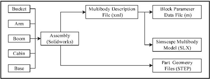
Figure 1 Translation steps.
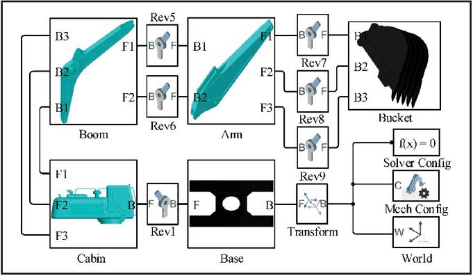
Figure 2 SimMultibody of the hydraulic excavator.
3 Modeling of Hydraulic Driving System
In this work, the hydraulic system is a positive flow control system, where the dual-pump and double-circuit are used to drive the working device to perform requisite actions. To better satisfy the requirements of flow distribution, priority control and fretting, the original hydraulic control method is replaced by the electromagnetic proportional valve to regulate the spool opening. The hydraulic circuits of the excavator working device mainly consist of four significant parts: the boom, the arm, the bucket and the swing. Among these circuits above, the boom is controlled by BOOM1 and BOOM2. When the boom is lifted, the interfaces b2 and b6 are selected. Confluence hydraulic oil from pump P2 and P1 is supplied to the head of the cylinder. When the boom is downed, the interfaces a6 and PbL are selected. Hydraulic oil from pump P2 is supplied to the rod. Similarly, the Arm is controlled by ARM1 and ARM2. Its mining operation corresponds to the interface a3 and a4, and the protrusion corresponds to the interface b3 and b4. Furthermore, the ARM1 has the function of flow regeneration because of gravitational forces when the arm is taken back under small load. Differently, the bucket and hydraulic motor are controlled by only one main valve, that is BUCKET and SWING, respectively. And the bucket circuit also has the function of confluence when the neutral bypass shutoff valve is closed by the signal XBp. The hydraulic circuits are depicted schematically in Figure 3.
Simscape Fluids organized by hydraulics, thermal liquid and fluid network interfaces has the characteristics of convenient physical modeling and intuitionistic simulation results. According to the function of every sub-physical system, the hydraulic circuits are encapsulated into several independent modules. Because they have the similar structure. For that reason, this paper just presents the boom subsystem model. The maximum displacement and normal pressure of the variable displacement pump are set 107 ml/r and 34.3 Mpa respectively. The maximum stroke of the boom value is set 8 mm. The piston diameter, the rod diameter and the length of stroke for the boom cylinder are set 120 mm, 85 mm, and 1285 mm respectively. The density of fluid is set 867.3 kg/m. According to Figure 3, hydraulic elements such as hydraulic pumps, directional values, hydraulic cylinders and so on in Simscape Fluids are called selectively. The function modules are combined with each other organically. Ultimately, the boom subsystem model is implemented, as shown in Figure 4.
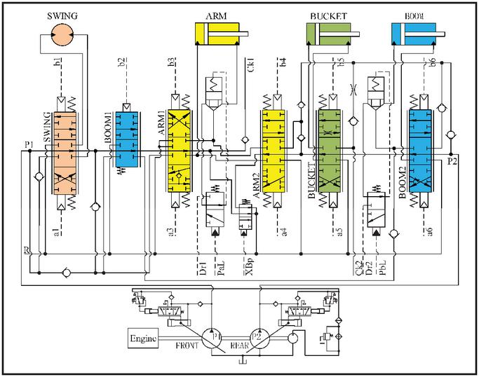
Figure 3 The hydraulic driving system.
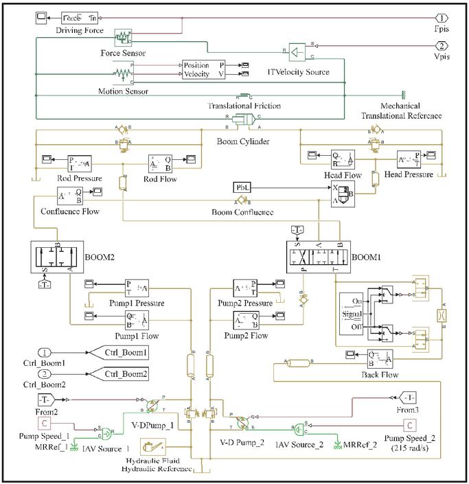
Figure 4 SimFluids model of the boom subsystem.
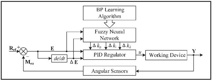
Figure 5 FNNPID controller structure.
4 FNNPID Control Strategy
In order to overcome the characteristics of nonlinearity in the working device system and achieve excellent control performance, FNN is applied to the incremental PID. And the network parameters are mainly adjusted by using the BP learning algorithm. Therefore, the FNNPID controller can automatically tune the proportional, integral and derivative coefficients online according to the deviation E and deviation change rate E. Its structure is arranged in Figure 5.
The control law of the incremental PID are as follows:
| (1) |
Where k, k and k are the proportional, integral and derivative coefficients respectively.
The structure for the FNN based on the Mamdani model, including five layers, is shown in Figure 6. Gaussian function is employed as the membership function. Moreover, two input variables [E; E] and three output variables [; ; ] are partitioned into seven linguistic variables: {NB, NM, NS, ZO, PS, PM, PB}. Fuzzy rules can be expressed as: If E is X and E is X Then k is Y and k is Y and k is Y. And the corresponding fuzzy rules are formulated according to the relevant prior knowledge and practical operation experience, which are developed in Table 2.
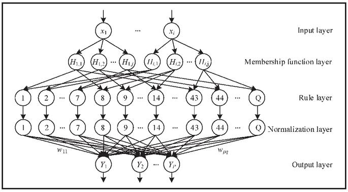
Figure 6 Fuzzy neural network structure.
Table 2 Fuzzy rules for the k, k, and k
| E | |||||||
| E | NB | NM | NS | ZO | PS | PM | PB |
| NB | PB | PB | PM | PM | PS | ZO | ZO |
| NB | NB | NM | NM | NS | ZO | ZO | |
| PS | NS | NM | NB | NB | NM | PS | |
| NM | PB | PB | PM | PS | PS | ZO | ZO |
| NB | NB | NM | NS | NS | ZO | ZO | |
| PS | NS | NM | NB | NB | NM | PS | |
| NS | PM | PM | PM | PM | ZO | NS | NS |
| NB | NM | NS | NS | ZO | PS | PS | |
| ZO | NS | NM | NM | NS | NS | ZO | |
| ZO | PM | PM | PS | ZO | NS | NM | NM |
| NM | NM | NS | ZO | PS | PM | PM | |
| ZO | NS | NS | NS | NS | NS | ZO | |
| PS | PS | PS | ZO | NS | NS | NM | NM |
| NM | NS | ZO | PS | PS | PM | PB | |
| ZO | ZO | ZO | ZO | ZO | ZO | ZO | |
| PM | PS | ZO | NS | NM | NM | NM | NB |
| ZO | ZO | PS | PS | PM | PB | PB | |
| PB | NS | PS | PS | PS | PS | PB | |
| PB | ZO | ZO | NS | NS | NM | NM | NM |
| ZO | ZO | PS | PM | PM | PB | PB | |
| PB | PM | PM | PM | PS | PS | PB | |
In the first layer, the input and output are defined as
| (2) |
Where i is the count of input units.
The membership layer represents the values of linguistic variables. The input and output as follow:
| (3) |
Where c is the central values of the membership function, and is the base width of the membership function.
In the rule layer, every neuron corresponds to one fuzzy control rule. And the minimum operation is replaced by multiplication, and the input and output is
| (4) |
Where q is the number of fuzzy control rules, k and k are the sequence number corresponding to every fuzzy linguistic variable.
In the normalization layer, the dimensional expressions are transformed into the non-dimensional elements to improve the convergence speed and accuracy of the model.
| (5) |
For the output layer, the input and output are described as
| (6) |
Where p denotes the number of output variables, and w is the connection weight between the fourth layer and the fifth layer.
In the FNN, the c, and w are optimized according to the gradient descent rule to reduce the error signal. Error function is
| (7) |
Where r(n) is the expected value, and y(n) is the output.
The update process is computed as follows:
| (8) |
Where n is the iteration times, and are the learning rate and the momentum coefficient respectively.
5 Simulation Results
In this section, according to the hydraulic excavators test methods, the initial positions of the boom, the arm and the bucket hydraulic cylinder are set to the full extension state. The mechanical kinematics model, the hydraulic driving system and the controller developed above are combined into a whole simulation model of multi-domain physical systems, Figure 7 shows the overall framework. Base on this model, an open-loop sinusoidal excitation response test with the boom as an example, Figure 8 shows the simulation results.
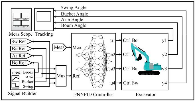
Figure 7 Multi-domain physical system simulation model.
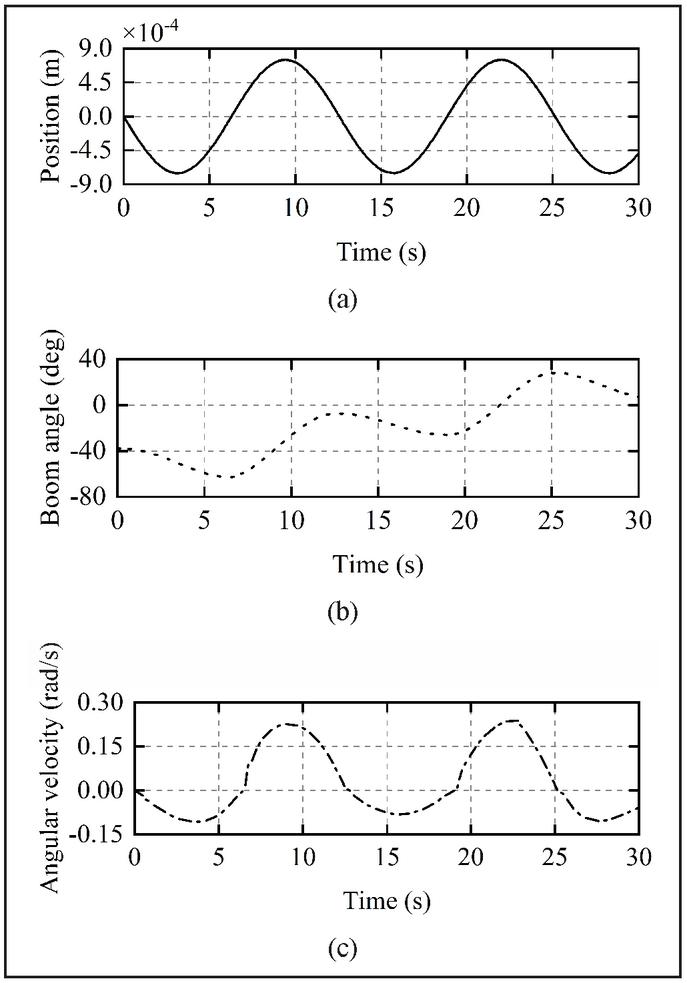
Figure 8 Open loop sinusoidal excitation response for the boom: (a) Spool displacement; (b) Boom angle; (c) Boom angular velocity.
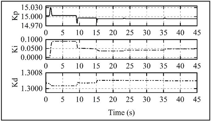
Figure 9 The process on the parameter of FNNPID controller.
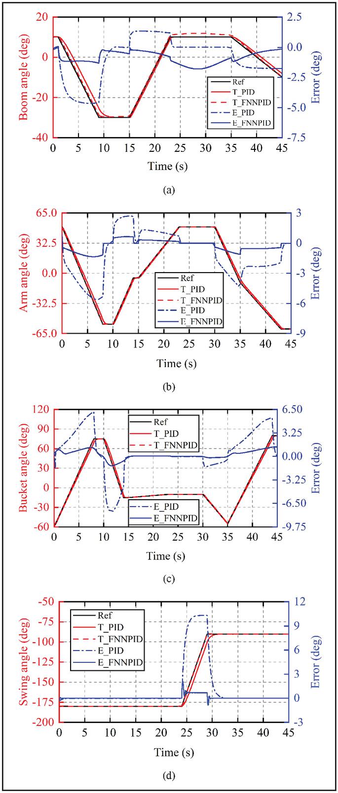
Figure 10 Closed loop trajectory tracking of the boom: (a) The boom; (b) The arm; (c) The bucket; (d) The swing.
In Figure 8, the input is a sinusoidal symmetrical signal, whereas the output curve presents indeed the rising trend. Therefore, the simulation results show that the dynamic characteristics of the hydraulic actuators for the working device are not symmetrical. Besides, they also indicate that the phenomenon of flat top and lag is caused by the existence of the dead zone. Namely, when the signal amplitude is close to zero, there is no response in the output angle curve. In this model, the initial joint angle values of the boom, arm, bucket and swing are 10.3, 49.2, 60.5 and 179.7, respectively. The closed-loop tracking response test using the PID and FNNPID control methods is carried out. Figure 9 shows the process on the parameter of kp, ki and kd.
Based on the multi-domain physical simulation model and nonlinear characteristic analysis, the FNNPID controller is developed by experimental debugging. Comparison results of closed loop trajectory simulation for the boom, arm, bucket and swing are shown in Figure 10. The maximum tracking error of the boom, arm, bucket and swing are reduced by 3, 3.2, 5.5 and 7.5 respectively. Compared with the conventional PID controller, the fuzzy neural network PID control strategy with small steady-state locus deviation and the rapid transient response velocity can effectively overcome the dynamic characteristics of the system.
6 Conclusion
A method of the multi-system hybrid modeling and simulation by using MATLAB has been proposed in this paper. The multi-domain physical fusion model established can effectively describe the movement process of the hydraulic excavator working device and contribute to deal with the multi-domain strong coupling characteristics in the development of the mechatronics product. Additionally, compared with the conventional PID control method, the demonstrated FNNPID controller has more excellent tracking performance.
Acknowledgment
This research was funded by the Construction Machinery with High Pressure Value Project (Project 2018YFB2001200).
Footnotes
*This work was supported by a Grant (Project 2018YFB2001200) from the National Key Research and Development Program of China.
References
[1] J. Park, B. Lee, S. Kang, P. Y. Kim, and H. J. Kim, “Online Learning Control of Hydraulic Excavators Based on Echo-State Networks,” IEEE Transactions on Automation Science and Engineering, vol. 14, no. 1, pp. 249–259, 2017.
[2] D. Hu, X. W. Zhao, and X. Ca, “Simulations of Hydraulic Pitch-regulated Mechanism of a Megawatt Wind Turbine,” Machine Tool & Hydraulics, vol. 37, no. 10, pp. 205–208, Oct. 2007.
[3] L. D. Hanh, K. K. Ahn, N. B. Kha, and W. K. Jo, “Trajectory control of electro-hydraulic excavator using fuzzy self tuning algorithm with neural network,” Journal of Mechanical Science and Technology, vol. 23, no. 1, pp. 149–160, Jan. 2009.
[4] B. Li, J. Yan, G. Guo, Y. H. Zeng, and Z. Peng, “The Electro-hydraulic Control System for Excavator and Its Discontinue Model,” Machine Tool & Hydraulics, vol. 40, no. 17, pp. 64–68, Sep. 2012.
[5] B. Li, J. Yan, G. Guo, Y. H. Zeng, and H. B. Qian, “Nonlinear Modeling and Analysis of Electro-hydraulic Proportional Control System for Excavator,” Mechanical Science and Technology for Aerospace Engineering, vol. 31, no. 9, pp. 1458–1462, Sep. 2012.
[6] Y. Li and Q. F. Wang, “Adaptive neural finite-time trajectory tracking control of hydraulic excavators,” Proceedings of the Institution of Mechanical Engineers Part I-Journal of Systems and Control Engineering, vol. 232, no. 9, pp. 909–925, 2018.
[7] S. Tafazoli, P. D. Lawrence and S. E. Salcudean, “Identification of inertial and friction parameters for excavator arms.” IEEE Transactions on Robotics and Automation, vol. 15, no. 5, pp. 966–971, Jan. 1999.
[8] S. Lee and P. Chang, “Modeling of a hydraulic excavator based on bond graph method and its parameter estimation,” Journal of Mechanical Science and Technology, vol. 26, no. 1, pp. 195–204, 2012.
[9] O. Muvengei and J. Kihiu, “Bond Graph Modeling of Mechanical Dynamics of an Excavator for Hydraulic System Analysis and Design,” Int J Mech Ind Aerosp Eng, vol. 3, pp. 772–780, 2009.
[10] H. Feng, C. B. Yin, W. Ma, H. F. Yu and D. H. Cao, “Parameters identification and trajectory control for a hydraulic system,” ISA Transactions, vol. 92, pp. 228–240, 2019.
[11] S. Mohapatra, R. Srivastava and R. Khera. “Implementation of a Two Wheel Self-Balanced Robot using MATLAB Simscape Multibody,” in The Second International Conference on Advanced Computational and Communication Paradigms, 2019.
Biographies

Zhen Zhang graduated from School of Automotive Engineering at Harbin Institute of Technology, Weihai, China, in 2020. His field of research is in system modelling, simulation and optimisation.

Jingming Zhang received a Ph.D. degree at School of Automotive Engineering at Harbin Institute of Technology, Weihai, China, in 2010. He is a professor fellow at vehicle system dynamics and chassis control technology for new energy Vehicles.

Nianning Luo is a doctor majoring in Fluid Transmission and Control in the School of Mechanical and Electrical Engineering at Harbin Institute of Technology. His field of research is in heterogeneous multi-agent cluster control and Integrated Control Technology for Construction Machinery System.
International Journal of Fluid Power, Vol. 23_3, 395–410.
doi: 10.13052/ijfp1439-9776.2337
© 2022 River Publishers