Multi-Chamber Actuator Using Digital Pump for Position and Velocity Control Applied in Aircraft
Marcos Paulo Nostrani1,*, Henrique Raduenz2, Alessandro Dell’Amico2, 3, Anders Petter Krus2 and Victor J. De Negri1
1Laboratory of Hydraulic and Penumatic Systems, Federal University of Santa Catarina, Florianópolis, Brazil
2Division of Fluid and Mechatronic Systems – FLUMES, Linköping University, Linköping, Sweden
3Saab AB, Linköping University, Linköping, Sweden
E-mail: marcos.nostrani@gmail.com; henrique.raduenz@gmail.com; alessandro.dellamico@saabgroup.com; petter.krus@liu.se; victor.de.negri@ufsc.br
*Corresponding Author
Received 09 June 2022; Accepted 21 July 2022; Publication 17 January 2023
Abstract
This paper presents a multi-chamber hydraulic actuator controlled by digital pumps and on/off valves, in order to improve the efficiency of hydraulic systems applied in aircraft for flight control. Hydraulic positioning systems are used in many different applications, such as mobile machinery, industry and aerospace. In aircraft, the hydraulic actuators are used at flight control surfaces, cargo doors, steering, landing gear and so one. However, the massive use of resistive control techniques, which throttles the passages of the hydraulic fluid, associated with internal leakage of the hydraulic components, make these systems low energy efficient. In order to improve their energy efficiency, digital hydraulics emerges as a promising solution mainly for mobile applications. In this paper a hydraulic positioning system for aircraft control surfaces using a multi-chamber actuator controlled by on/off valves and a digital pump is proposed. The use of a digital pump with three fixed displacement pumps can provide eight different volumetric displacement outputs. The multi-chamber actuator with four areas can operate in two different modes, normal or regenerative, resulting in six different equivalent areas. The regenerative mode allows the actuator to achieve higher actuation velocity values with smaller pumps. These equivalent areas combined with the different supplied flow rates can deliver 43 different discrete output velocity values for the actuator, in steady-state. For the system dynamic analyses, three mathematical simulation models were developed using MATLAB/Simulink and Hopsan, one for the digital system, and two for the conventional solutions applied in aircraft (Servo Hydraulic Actuators (SHA) and Electro Hydrostatic Actuator (EHA)). The simulation results demonstrate that the digital actuator can achieve, for position control, a maximum position error, in a steady-state, of 0.7 mm. From the energy consumption point of view, the digital circuit consumes 31 times less energy when compared with the SHA and 1.7 when compared to the EHA, resulting in an energy efficiency of 54%.
Keywords: Digital hydraulics, multi-chamber actuators, digital pumps, position control.
1 Introduction
Nowadays, one of the main global concerns is to reduce the carbon dioxide (CO) content emitted in the atmosphere due to the increasing global warming in recent decades. The combustion of fossil fuels is the biggest contributor to emissions of carbon dioxide in the atmosphere [1]. For instance, in [2] it is quoted that in 2017, the aviation industry produced 859 million tons of CO. The main reason for that is the aircraft propulsion technology, which is dependent on internal combustion engines [3].
In order to improve the energy efficiency of the aircraft, reducing the fuel consumption, nowadays there are some researches being carrying out in this context [4, 5].
According to [4], there are four different power sources in a conventional aircraft, Pneumatic Hydraulic Electric and Mechanical, where the hydraulic system is responsible for around 240 kW in a Boeing 737 or Airbus A320 type aircraft.
To improve the aircraft energy efficiency, the concept MEA (More Electric Aircraft) is being largely discussed in the last decades. This concept aims to replace the pneumatic, hydraulic and mechanical systems by electrical systems [4]. According to [6], this technology can bring some advantages as maintenance and mass reduction. However, modern aircraft still uses hydraulic systems for the control of primary and secondary flight control surfaces. The widespread use of hydraulic actuators in commercial aircraft is due to many advantages such as, the hydraulic fluid is almost incompressible, mechanical stiffness, fast dynamic response [7].
Despite all the advantages, hydraulic systems present a low energy efficiency, which is caused by the pressure and flow control techniques that throttle the flow through passages resulting in thermal losses and internal leakage in the hydraulic components. In order to overcome this low energy efficiency, other configurations of actuators, based on power-on-demand were developed through the years, as the Electro Hydrostatic Actuators – EHA [8, 9] and solutions using variable displacement pumps. As stated in [10], one of the disadvantages of the EHAs is that the electric motors keep consuming energy even for constant output, which makes the internal dissipation of heat difficult. In the systems that use variable displacement pumps, [11] quote that for cruse flights, the pumps have their volumetric displacement set in a low value range, mainly for supply the system internal leakage. Nevertheless, in this condition, the pump operates in a low efficient range.
To improve the hydraulic systems efficiency, the digital hydraulics emerges as a new promising solution over the last decades. In this concept, hydraulic circuit and components are set in order to reduce the throttle losses and internal leakages. The application of this concept in aircraft is being studied jointly by LASHIP/UFSC, FLUMES/LiU and Saab AB over the last few years, as shown in [5] and [12].
In this paper, an actuator topology using digital pump, on/off valves and a multi-chamber hydraulic cylinder is proposed for position and velocity control for application in aircraft flight control. The use of the multi-chamber actuator has been studied by several authors in the last decades. In [13], a four-chamber actuator with two constant pressure sources for force control is used. In [5] and [12], a similar configuration using three different pressure sources for application in flight control is presented. In terms of digital pumps, [14] used a parallel pump associated with on/off valves and a four-chamber actuator for velocity control. The authors in [15] use digital pumps in closed circuit for velocity control in actuators with two chambers.
This paper is organized as follows. In Section 2, the main hydraulic actuators used in aircraft are presented. In Section 3, the proposed actuator using digital pumps, on/off valves and multi-chamber cylinder is described. Section 4 presents the system model and the SHA (Servo Hydraulic Actuator) and EHA models used for comparing the systems behavior and efficiencies. Section 5 presents simulation results. Lastly, Section 6 presents the main conclusions.
2 Aircraft Hydraulic Control Actuators – EHA and SHA
In aircraft, the hydraulic actuators are responsible for the actuation of the primary and secondary control surfaces [16], landing gears, cargo doors, steering [17] and so on. One of the hydraulic actuators used in aircraft is the SHA – Servo Hydraulic Actuator. According to [18], these actuators are the most commonly used to control the aircraft control surfaces, where normally a centralized hydraulic power unit is used. In SHAs, a servo valve is connected to the chambers of the actuator. Normally, this kind of valve is a spool type, which due to their internal clearances, has internal leakage.
As mentioned in Section 1, in cruise-flights the variable displacement pumps, which are currently used in aircraft, are set to a low volumetric displacement range in order to compensate the internal leakages in valves and other components and keep the system pressurized. However, in this condition, the pumps work in a low volumetric efficiency range [19].
Another configuration of actuator that are currently in study and being applied in aircraft is the Electro Hydrostatic Actuator – EHA. According to [20], EHA is basically a self-contained hydraulic actuator, which is controlled by a hydraulic pump connected to a variable speed electric motor. [21] highlight that other configurations can be used in EHAs, as variable displacement pumps with a fixed speed electric motor or a variable displacement pump with a variable speed electric motor.
The main advantages of using EHAs are the replacement of the centralized hydraulic power units by decentralized ones, reduction of the maintenance cost due to the facility to replace an EHA in case of fault, reduction of the energy losses due to the less use of components that throttle the flow [21].
In conventional hydraulic systems used in aircraft, the pumps have large volumetric displacements in order to supply hydraulic fluid to all actuators in a specific hydraulic circuit. For instance, in the Airbus A380, the volumetric displacement of the hydraulic pumps can achieve 47 cm/rev [22]. Another point to be mentioned is, for conventional hydraulic systems, the pumps work normally in a constant rotational frequency and output pressure, such that they can be optimized for these operation conditions [22]. In Electro-Hydrostatic Actuators, the rotational frequency of the pumps can achieve values of 10000 to 16000 rpm [22, 23], and the volumetric displacement is around 0.5 cm/rev [22]. Furthermore, the pumps need to operate in both directions of rotation and have to be able to accelerate and decelerate with very low response time.
3 Digital Hydraulic Actuator Proposed
In digital hydraulics, components like the variable displacement pumps and proportional and servo valves are replaced by ordinary hydraulic components, such as on/off valves and fixed displacement pumps. However, these components can be assembled/operated in different ways, as in parallel (Parallel Connection Technology) or time switched (Switched Hydraulics).
The digital hydraulic actuator presented in this paper comprises primary and secondary conversion units. The primary conversion unit (electric to hydraulic power) is composed by three fixed displacement pumps with different volumetric displacements connect in the same shaft, three on/off valves, three relief valves and three check valves (Figure 1).
With the use of three fixed displacement pumps, it is possible to obtain eight different output flow rate values, through the combinations of the pumps. The on/off valves are in charger for directing the pump flow rates to the reservoir or to the system. The check valves have the function of isolating the line of each pump and prevent pressure peaks from one pump to another. The relief valves were installed just to limit the maximum pressure of the system, for safety reasons. However, these valves should not open in normal operation conditions in order to avoid energy losses.
For the secondary conversion unit, on/off valves and a multi-chamber cylinder were used, respectively. The on/off valves are responsible for connecting the flow rate, which comes from the primary conversion unit, to each actuator chamber or each chamber to the reservoir. For the proposed actuator, two valves were used for each actuator chamber.
The multi-chamber actuator is a hydraulic linear cylinder with a number of chambers equals or higher than four. The number of chamber combinations that can be used determines the resolution for a digital system. In this paper, a cylinder with four chambers was used. (Figure 1).
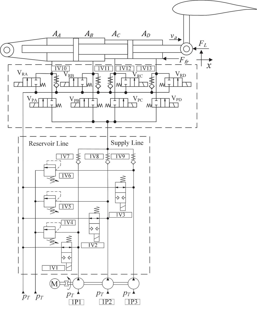
Figure 1 Digital electro hydrostatic actuator – DEHA.
The hydraulic multi-chamber actuator combined with the on/off valves present two operational modes: non-regenerative and regenerative. In the non-regenerative mode, the chambers A and C, for the forward movement, receive fluid at the same time and the chambers B and D are connected to the reservoir. In the regenerative mode (Figure 2), the chambers that are decreasing the volume can be directed to the chambers that are increasing the volume.
When the actuator operates in regenerative mode, the chambers A and C receive a booster of flow rate, which increases the actuator velocity, but the load capacity is reduced, due to the regenerative chamber that remains pressurized. In non-regenerative mode, the actuator has the higher load capacity, but the velocity is lower.
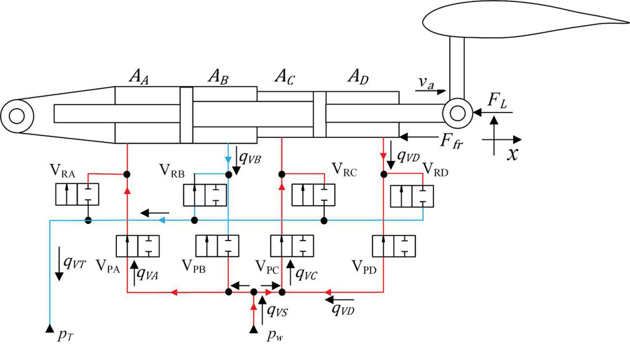
Figure 2 Multi-chamber actuator in regenerative mode.
The velocity of the actuator , in steady state, can be evaluated according to
| (1) |
where is the supplied flow rate [m/s], is the resultant area [m] and is the regenerative area [m]. The resultant area is the sum of the areas of the chambers that are increasing the volume (Chambers A and C for the forward movement and B and D for the backward movement) In Figure 2, the regenerative area corresponds to the chamber D area.
According to [19], the power and dynamic requirements can vary according to the type of aircraft, where the typical range for the actuator stroke is 20 to 700 mm, 20 to 500 mm/s for the actuator speed and 20 to 350 kN for the force. In this paper, step response of, 50 mm, a setting time of 1 s and a maximum force () of 20 kN at 210 bar in regenerative mode, were considered. Using the methodology present in [24] and [25] the maximum actuator velocity was obtained , resulting in 0.111 m/s.
The areas of the linear actuator used in the system are 1544, 1102, 707 and 1344 mm, for the chambers A, B C and D, respectively.
With this actuator, the resultant area for the forward movement is 2279 mm and the maximum equivalent area is 907 mm. The maximum equivalent area is the area that the actuator will achieve the maximum velocity in regenerative mode using the higher regenerative area . Therefore, the necessary maximum flow rate [m/s] for the actuator achieve the maximum velocity is m/s (6.2 L/min).
The volumetric displacements of the pumps are determined based on the maximum flow rate and rotational frequency (1200 rpm – 20 Hz), being , and equals to m, m and m, respectively. With the use of a digital pump with three fixed displacement pumps, eight different supply flow rates can be achieved, as are shown in Table 1.
Table 1 Different combinations of pumps
| Pump 1 | Pump 2 | Pumps 3 | Flow Rate [l/min] |
| 0 | 0 | 0 | 0 |
| 1 | 0 | 0 | 1.2 |
| 0 | 1 | 0 | 2.4 |
| 1 | 1 | 0 | 3.6 |
| 0 | 0 | 1 | 3.76 |
| 1 | 0 | 1 | 4.98 |
| 0 | 1 | 1 | 6.18 |
| 1 | 1 | 1 | 7.38 |
With the used of the cylinder with four chambers, six different combinations of chambers can be achieved. All these combinations are shown in Table 2.
Table 2 Actuator chambers combinations
| Chambers Combinations | Equivalent Area [mm] |
| Chamber A with Chamber C | 2251 |
| Chamber A with Chamber C and regeneration from Chamber B | 1149 |
| Chamber A with Chamber C and regeneration from Chamber r D | 907 |
| Chamber B with Chamber D | 2446 |
| Chamber B with Chamber D and regeneration from Chamber A | 902 |
| Chamber B with Chamber D and regeneration from Chamber C | 1739 |
Considering all combinations of pumps and areas, the actuator can achieve 43 different velocities, including the zero value (Equation (1)). Figure 3 present the velocities that the actuator can achieve.
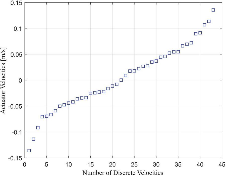
Figure 3 Distributions of the actuators velocities.
As can be seen in Figure 3, there is certain linearity of the velocity values for a range of 0.075 to 0.1 m/s, approximately. The linearity behavior is interesting for the position control point of view.
The actuator proposed in this paper, due to its similarity with the Electro Hydrostatic Actuators, where the pump and the cylinder comprises the actuator, was called Digital Electro Hydrostatic Actuator – DEHA.
4 Actuator Modelling and Control
4.1 Modelling and Parameters Values
The modeling of the proposed actuator was developed in the numerical simulation software Hopsan 2.9.0, which is based in the Transmission Line Method – TLM.
The on/off valves were modeled, according to the orifice flow rate equation, being
| (2) |
where is the valve flow rate [m/s], the discharge coefficient [1], the valve pressure drop [Pa], the fluid specific mass [kg/m], the valve spool diameter [m], the maximum spool displacement [m] and [1] the spool diameter fraction.
The valves dynamics have a significant influence in the system behavior. These dynamics were modelled according [27]. The valve parameters are listed in Table 3.
Table 3 Digital valves parameters
| Name | Symbol | Value |
| Time to energize the solenoid | 0.003 s | |
| Time to de-energize the solenoid | 0.03 s | |
| Opening valve spool dynamics | 0.041 s | |
| Closing valve spool dynamics | 0.062 s | |
| Discharge coefficient | 0.65 | |
| Spool diameter | [0.0046, 0.0042] m | |
| Maximum spool displacement | 0.001 m | |
| Spool diameter fraction | [0.5, 1] | |
| Pressure drop | [20, 6] bar | |
| Fluid specific mass | 850 kg/m | |
| Opening natural frequency | 150 rad/s | |
| Closing natural frequency | 100 rad/s |
The movement of the multi-chamber actuator was modeled using the Newton’s Second Law, being.
| (3) |
where and are the A, B, C and D chambers areas, respectively, and are the pressures of the A, B, C and D chambers, respectively, is the friction force and is the total mass in movement [47 kg]. The friction force was modeled using the Lugre model described in [26]. The check valves were modeled through the Equation (4),
| (4) |
where is the check valve flow rate [m/s], is the check valve flow coefficient, which is [m/(sPa)] and the is the check valve pressure differential [Pa]. For the opening dynamic behavior for the check valves, a second order transfer function was implemented, where the natural frequency is 314.15 rad/s and the damping factor 0.7. The check valve pre-load pressure is Pa.
The leakage in the fixed displacement pumps was modeled as a laminar orifice in parallel of each pump. The leakage coefficients are , , and m/(sPa), for the pumps 1, 2, and 3, respectively.
4.2 System Control
For the system control, the MATLAB/Simulink software was used. The diagram of the system control is presented in Figure 4.
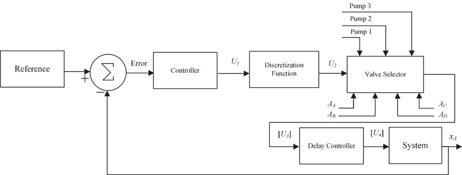
Figure 4 System control diagram.
A PI controller was implemented and its output is sent to a discretizing function. As the actuator presents a discrete number of velocities (see Figure 3), the discretization function aims to set the controller output signal in one of the predefined velocities. Subsequently, the valve selector is responsible for selecting each valve that should be activated or not depending on the desired velocity as represented by the matrix shown in Figure 5.

Figure 5 Matrix with the valve combinations.
In the Matrix presented in Figure 5, the second row represents the velocity available in the system. The third row represents the switching cost function, which is based in [28]. This function is calculated with the difference between the desired velocity required by the PI controller and the velocity presented in the system.
The rows four to six represent the status of the on/off valves for the pumps one, two and three, respectively. The rows seven to fourteen are responsible for the valves of the actuator’s chambers.
With the definition of the status of all valves for the desired velocity, the output signal from the valves selector is sent to the delay controller, responsible for the synchronization of the valves, and then sent to the system.
For the valve selector, three-time intervals, , were implemented based on those used in [26] and [27]. The is the time interval, which the valve selector algorithm should operate according to the simulation sample time (1 ms). The defines the time that the combination valve matrix should be recalculated and the defines the minimum time interval for a valve combination change, which should be higher than the dynamics of the valves.
4.3 SHA and EHA Actuators
In order to compare the results obtained with the digital hydrostatic actuator (DEHA) proposed in this paper, two actuators, using the traditional topologies, were analyzed under the same work conditions (maximum velocity and load), that are, a Servo Hydraulic Actuator – SHA and an Electro-Hydrostatic Actuator. Figure 6 show the SHA in a tandem configuration with two servo valves and a variable displacement pump. The tandem configuration was chosen due to its redundancy, which naturally occurs in the DEHA.

Figure 6 Servo hydraulic actuator – SHA.
The servo valves present internal leakage that causes energy losses. This leakage was modeled according to the theorical and experimental results presented in [29]. The two valves combined present a leakage around 2 L/min in a pressure differential of 210 bar. Therefore, the variable displacement pump needs to be operating in a low volumetric displacement range. The volumetric efficiency was modeled according to [30] as a function of the volumetric displacement and the output pressure. Based on that, a pump leakage coefficient was calculated as
| (5) |
where, is the pump rotational frequency [rad/s], is the pump maximum volumetric displacement [m/rev], is the pump displacement control signal [1], the volumetric efficiency, is the pump output pressure for the SHA [Pa] and is the reservoir pressure for the SHA [Pa]. The pump displacement control signal is calculated according to the position error [m] (Equation (6)).
| (6) |
The areas A, B, C and D for the SHA are equal to 453.5 mm. The parameters for the SHA model are presented in Table 4.
Table 4 SHA parameters
| Name | Symbol | Value |
| Cylinder Stroke | 0.2 m | |
| Bulk modulus | Pa | |
| Pump maximum volumetric Displacement | m/rot | |
| SHA reservoir pressure | Pa | |
| Rotational Frequency | 125.66 rad/s |
The dynamics of the servo valve and the position of the pump volumetric displacement were considered as the second order. Thus, the natural frequency for the valve and the displacement control were implemented as 1047.2 and 209.43 rad/s, respectively and the damping factor for both components is 0.9.
For the Electro Hydrostatic Actuator – EHA, the modeled system is presented in Figure 7.
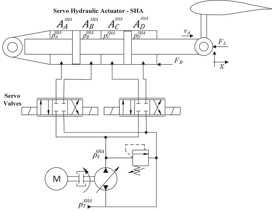
Figure 7 Electro hydrostatic actuator – EHA modelled.
The pump was modeled as a fixed displacement pump with a variable rotational frequency. Therefore, in this system, the output signal from the controller is converted to rotational signal for the pump, with a second order dynamics.
The pump leakage is modeled analogously as the DEHA system, with a laminar orifice in parallel to the pump. The parameters for the EHA are presented in Table 5.
Table 5 EHA parameters
| Name | Symbol | Value |
| Chamber A area | mm | |
| Chamber B area | mm | |
| Cylinder Stroke | 0.2 m | |
| Dead volume of chamber A | m | |
| Dead volume of chamber B | m | |
| Bulk modulus | Pa | |
| Pump volumetric displacement | m/rot | |
| EHA reservoir pressure | Pa | |
| Pump natural frequency | 62.83 rad/s | |
| Pump Damping factor | 0.9 |
5 Simulation Results
In this section, the main results obtained with DEHA, SHA and EHA systems will be presented. The load force applied in both systems was modeled as a spring load according to Equation (7).
| (7) |
5.1 Velocity Control
In order to verify the change between two different velocity levels, Figure 8 presents the results obtained for a step input signal and Figure 9 the pressure in the chambers of the cylinder.

Figure 8 Actuator response for a velocity step input signal.
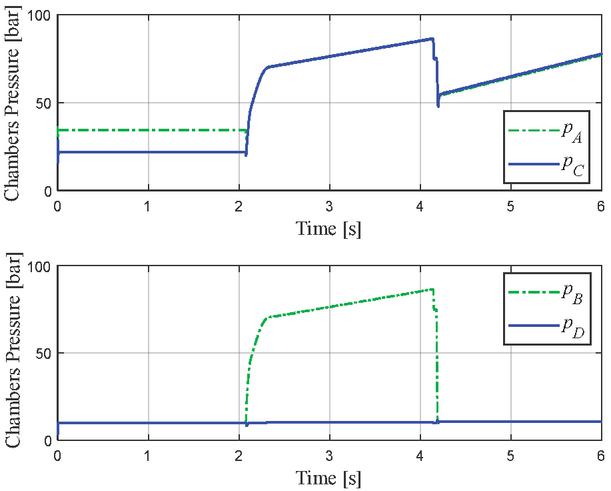
Figure 9 Actuator pressures for a velocity step input signal.
As can be seen in Figure 8 and in Figure 9, the actuator can follow the velocity reference, with some difference caused by the leakage in the pumps. The transitions between two different velocity levels present some oscillations. These oscillations are caused by the fast switching of the on/off valves between different pressure levels and due to the friction and the load forces. However, these oscillations do not cause higher alterations in the actuator movement.
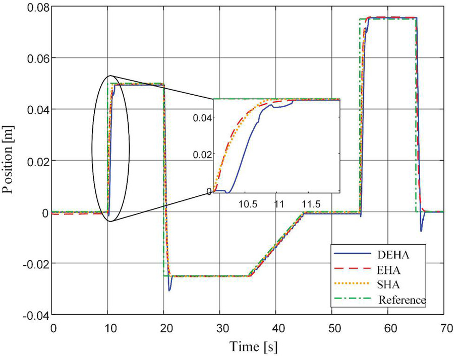
Figure 10 Systems response. Position.
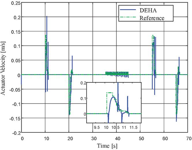
Figure 11 DEHA response. Velocity control.
5.2 Position Control
Considering the operation as positioning systems, the proportional gains for the DEHA, SHA and EHA were adjusted as 1.2, 1 and 1, the integral gains as 0.01, 0.01 and 0.1, respectively. A gain of 2.71 was used to convert the position signal error in velocity for the DEHA, 200 to converter the position signal for the servo valve volt signal (10 to 10) V in the SHA and 2513.2 to convert the position error in angular velocity for the EHA. The is s, is 0.104 s and the is 0.064 s.
Figure 10 presents the position responses for all systems and Figures 11 and 12 the velocity control signal and the position error, respectively for the DEHA.
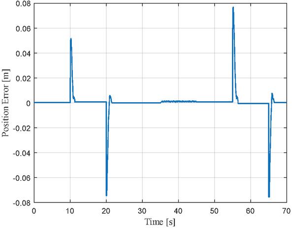
Figure 12 DEHA response. Position error.
As can be noticed in Figure 10, the SHA and the EHA have similar behaviors, however, the DEHA present some oscillations, which are caused by the valve switching. Also, the DEHA response presents a delay around 40 ms to start the movement. This delay is caused by the delay controller, which takes 40 ms to send the opening signal to the valves. In Figure 13, the signal for the pump valves is presented and in Figure 14 the pressure in actuator chambers is shown.

Figure 13 DEHA pumps valves signals.
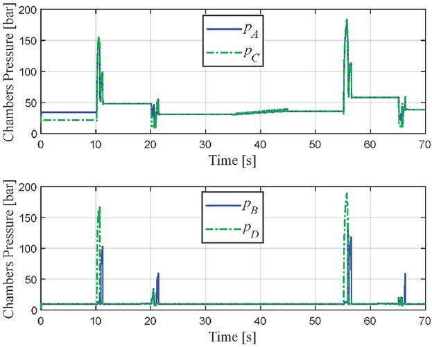
Figure 14 DEHA actuator’s chambers pressure.
For the period of 37 to 45 s, only pump 1 is requested. However, the velocity requested for the actuator does not match with the ones present by the combinations of pumps and chambers, which causes the continuously switching of this pump. For the pressure in the actuator chambers, some pressure peaks are also observed due to the fast switching of the valves, which connects the cylinder chamber to the outlet of the pumps in a short period of time.
In order to compare the energy efficiencies, the supplied and the output energies were calculated. For the DEHA and the SHA systems, the supplied energy was calculated by the multiplications of the pumps flow rate and the pressure differences. The output energy was calculated by the multiplications of the actuator force and the velocity.
For the EHA actuator, the calculus for the supplied energy and the output energy were carried out considering that the load can supply hydraulic energy when the actuator is in backward movement. Figures 15 and 16 present the supplied energy and the output energy for both systems, respectively.
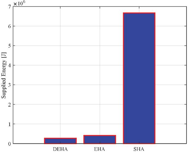
Figure 15 Supplied energy.

Figure 16 Output energy.
The energy efficiency was calculated by the ration of the output energy and the supplied energy. The results for the energy efficiency are present in Figure 17.

Figure 17 Energy efficiency.
The results show that the SHA system dissipates much more energy than the DEHA and EHA. This energy dissipation is practically converted in heat for the hydraulic system. In the DEHA and EHA, the energy dissipation is considerably smaller. Consequently, the cooling system can be reduced, saving weight for the aircraft. For the energy efficiency point of view, the DEHA is around 31 time more efficient than the SHA, and around 1.7 than the EHA. With these efficiency values, the DEHA can be a promising solution for a more efficient actuator alternative, for application in aircraft.
6 Conclusions
In this paper, an aircraft actuator using digital pump, on/off valves and multi-chamber actuator comprising a Digital Electro Hydrostatic Actuator – DEHA, was presented. In addition, a SHA and EHA were modeled in order to be compared with the proposed actuator. The DEHA actuator using a digital pump with three pumps and a multi-chamber actuator with four chambers can provide 43 different velocity values. In the transition of different velocity levels, oscillations occur due to the valve switching between two different pressure levels. However, the actuator position has no significant effect. The leakage at the pumps causes a decrease in the velocity of the actuator in steady-state. For position control, the DEHA can achieve similar results when compared with the SHA and EHA. Nevertheless, pressure peaks occur during switching of the valves. For a ramp input signal, where the velocity does not match with velocity combinations presented in the DEHA actuator, the controller chooses the closer velocity values presented in the velocity matrix. This behavior causes a stair waveform in the position. Due to the use of a digital pump, which remains with low output pressure, when the actuator is not moving, it dissipates less energy than the SHA and EHA. This results in energy efficiency around 54%, being 1.7 times higher than the EHA and 31 times than the SHA, thus demonstrating that the DEHA can be an interesting solution for the development of more efficient actuators to be applied in aircraft.
Acknowledgment
This work was carried out with the support of CISB, Swedish-Brazilian Research and Innovation Center, Saab AB Svenska Aeroplan AB, CAPES – Coordination for the Improvement of Higher Education Personnel, CNPq – National Council for Scientific and Technological Development, Linköping University and Federal University of Santa Catarina.
References
[1] Lotfalipour, M. R., Falahi, M. A., Malihe, A. Economic Growth, CO Emissions, and Fossil Fuels Consumption in Iran. The International Journal of Energy. Elsevier. 2010.
[2] Terrrenoire, E., Hauglustaine. D. A., Gasser, T., Penanhoat. O. The Contribution of Carbon Dioxide Emissions from the Aviation Sector to Future Climate Change. Journal of Environmental Research Letters. 2019.
[3] Sliwinski, J., Gardi, A., Marino, M., Sabatini, R. Hybrid-Electric Propulsion Integration in Unmanned Aircraft. International Journal of Energy. 2017.
[4] Bozhko, S., Hill, C. I., Yang, T. More-Electric Aircraft Systems and Modeling. Wiley Encyclopedia of Electrical and Electronics Engineering. 2018.
[5] Belan, H, B., Locateli, C. C., Lantto, B., Krus. P., De Negri, V. J.; Digital Secondary Control Architecture for Aircraft Application. The Seventh Workshop on Digital Fluid Power, February 26–27, Linz, Austria, 2015.
[6] Bennett, J. W., Atkinson, G. J., Mecrow, B. C., Atkinson, D. J. Fault-Tolerant Design Considerations and Control Strategies for Aerospace Drives. IEEE Transactions on Industrial Electronics, v. 59 n. 5, 2012.
[7] Wang, S., Tomovic, M., Liu, H. Commercial Aircraft Hydraulic Systems. Shanghai Jiao Tong University Press Aerospace Series. Published by Elsevier Inc. 2016.
[8] Qiao, G., Liu, G., Wang, Y., Ma, S. A Review of Electromechanical Actuators for More/All Electric Aircraft Systems. Journal of Mechanical Engineering Science. 2017.
[9] Jian, F., Maré J. C., Yongling, F. Modelling and Simulation of Flight Control Electromechanical Actuators with Special Focus on Model Architecting, Multidisciplinary Effects and Power Flows. Chinese Journal of Aeronautics. 2016.
[10] Rongjie, K., Zongxia, J., Shaoping, W., Lisha, C. Design and Simulation of Electro-Hydrostatic Actuator with a Built-in Power Regulator. Chinese Journal of Aeronautics. 2009.
[11] Pinto, L. P. G., Belan, H. C., Locateli, C. C., Krus, P., De Negri, V. J., Lanto, B. New Perspectives on Digital Hydraulics for Aerospace Applications. Aerospace Technology Congress, Solna Stockholm, 11–12 October, 2016.
[12] Dell’Amico, A., Simon, D., Ward, S., Pinto, L. P. G., Lantto, B., De Negri, V., Krus. P., A Hybrid Digital-Proportional Hydraulic Actuation System for Aircraft Flight Control. 31st Congress of the International Council of the Aeronautical Sciences. Belo Horizonte, Brazil, September, 2018.
[13] Linjama, M. Vihtanen, H-P. Sipola, A. Vilenius, M. Secondary Controlled Multi-Chamber Hydraulic Cylinder. The 11th Scandinavian International Conference on Fluid Power. Linköping. Sweden. 2009.
[14] Pynttäri, O. N. Linjama, M. Laamanen, A. Huhtala, K. Parallel Pump-Controlled Multi-Chamber Cylinder. Symposium on Fluid Power & Motion Control. Bath. United Kingdom. 2014.
[15] Heitzig, S. Theissen, H. Aspects of Digital Pumps in Closed Circuit. The Fourth Workshop on Digital Fluid Power. Linz, Austria. 2011.
[16] Moir, I., Seabridge, A. Aircraft Systems: Mechanical, Electrical, and Avionics Subsystems Integration. 3rd Ed. John Wiley & Sons, Ltd. ISBN 978-0-470-05996-8. 2008.
[17] Ward, S. Digital Hydraulics in Aircraft Control Surface Actuation. Fluid and Mechatronic Systems Master Thesis. Linköping University. 2017.
[18] Márton, L. Ossmann, D. Energetic Approach for Control Surface Disconnection Fault Detection in Hydraulic Aircraft Actuators. 8th Symposium on Fault Detection, Supervision and Safety of Technical Processes. Mexico City, Mexico. 2012.
[19] Maré, J. C., Aerospace Actuators 1: Needs, Reliability and Hydraulic Power Solutions. John Wiley & Sons, Inc. 2016.
[20] Bossche, van den D. The A380 Flight Control Electrohydrostatic Actuators, Achievements and Lessons Learnt. 25th International Congress of the Aeronautical Sciences. 2006.
[21] Alle, N., Hiremath, S. S., Makaram, S., Subramaniam, K., Talukdar, A. Review on Electro Hydrostatic Actuator for Flight Control. International Journal of Fluid Power. Taylor & Francis. 2012.
[22] Maré, J. C., Aerospace Actuators 2: Signal-by-Wire and Power-by-Wire. John Wiley & Sons, Inc. 2017.
[23] Zhang, J., Chao, Q., Xu, B. Analysis of the Cylinder Block Tilting Inertia Moment and its Effect on the Performance of High-Speed Electro-Hydrostatic Actuator Pumps of Aircraft. Chinese Journal of Aeronautics. 2016.
[24] De Negri, V. J., Ramos Filho, J. R. B., Souza, A. D. C. de. A Design Method for Hydraulic Positioning Systems. 51th National Conference on Fluid Power (NCFP), Las Vegas, USA. 2008.
[25] Muraro, I., Teixeira, P. L., De Negri, V. J. Effect of proportional valves and cylinders on the behavior of hydraulic positioning systems. In: ASME/BATH Symposium on Fluid Power & Motion Control, Sarasota, FL. pp. 1–9. 2013.
[26] Belan, C. H., Sistemas de Atuação Hidráulicos Digitais para Aviões com Foco em Eficiência Energética. Tese de Doutorado em Engenharia Mecânica. Universidade Federal de Santa Catarina. 2018.
[27] Montavani, I. J., Belan, C. H., De Negri, V. J., Análise do Chaveamento entre Válvulas para Atuador Hidráulico Digital (DHA). XXII Congresso Brasileiro de Automática. 2018.
[28] Huova, M., Linjama, M., Kalevi, H. Study of Energy Losses in Digital Hydraulic Multi-Pressure Actuator. The 15th Scandinavian International Conference on Fluid Power, SICFP’17, Linköping, Sweden, June 7–9, 2017.
[29] Cruz, D. P. M. Análise do Sistema Hidráulico Digital para Aviões com Foco em Eficiência Energética. Dissertação de Mestrado em Engenharia Mecânica. Universidade Federal de Santa Catarina. 2018.
[30] Bravo, R. R. S., Sistema Hidráulico-Pneumático de Frenagem Regenerativa e Hibridização de Veículos Comerciais. Tese (Doutorado em Engenharia Mecânica) Universidade Federal de Santa Catarina, Florianópolis, 2017.
Biographies
Marcos Paulo Nostrani received his Master degree in 2015 and his D. Eng. degree in 2021, both from the Federal University of Santa Catarina (UFSC). He is currently a professor at the Federal University of Santa Catarina where he works with the Laboratory of Hydraulic and Pneumatic Systems-LASHIP in the development of digital hydraulic systems for aeronautical applications.

Henrique Raduenz received his Master degree in 2018 from the Federal University of Santa Catarina (UFSC). He is currently a Ph.D. Student at Linkoping University Sweden in the Division of Fluid and Mechatronic Systems – Flumes.

Alessandro Dell’Amico received his Ph.D. degree in 2016 from Linkoping University, Linköping, Sweden. Nowadays, he is an Adjunct Senior Lecturer in the Department of Management and Engineering of the Linköping University. His research interests include modeling, simulation, and control of fluid power systems, mechatronic systems, and digital hydraulics, and applications are in automotive systems, aeronaut systems and construction machinery.

Anders Petter Krus received the Master of Science degree in mechanical engineering and the Ph.D. degree from Linkoping University, Linköping, Sweden. He is currently a Professor in fluid and mechatronic systems at Linkoping University, Linköping, Sweden. His research interests include fluid power, mechanical, and mechatronic systems technology, specifically focusing on system dynamics, control, system simulation, optimization, system design, and design automation, and applications are in aircraft design, road vehicles, and construction machines.
Victor J. De Negri received his D. Eng. degree in 1996, from the Federal University of Santa Catarina (UFSC). In 2010 he took a 7-month sabbatical at PTMC, University of Bath, UK. He has been a Professor at the Mechanical Engineering Department at UFSC since 1995. He is currently the Head of the Laboratory of Hydraulic and Pneumatic Systems (LASHIP). His interest areas include hydraulic components, power generating plants, mobile hydraulics, pneumatic systems and positioning systems.
International Journal of Fluid Power, Vol. 24_1, 1–28.
doi: 10.13052/ijfp1439-9776.2411
© 2023 River Publishers