Simulation and Experiment of Electromagnet for High-Speed On-off Valve for Vehicle Shifting System*
Qingjun Yang1,*, Yudong Liu1, Rui Zhu1, Qi Mao1, Rizhi Dong1 and Hongxuan Jiang2
1Dept. Fluid Control and Automation, Harbin Institute of Technology, Harbin, China
2National Key Lab of Vehicular Transmission, China North Vehicle Study Institute, Beijing, China
E-mail: yqj@hit.edu.cn; yudon_liu@163.com; 354732175@qq.com; 1354463139@qq.com; 940762474@qq.com; hxjiang201@163.com
*Corresponding Author
Received 09 June 2022; Accepted 21 July 2022; Publication 17 January 2023
Abstract
The high-speed on-off valve is the core component for adjusting the oil pressure of the pressure reducing valve in the clutch shifting system of engineering vehicles, and its response speed is one of the important indicators to measure its performance. In order to improve the dynamic performance of high-speed on-off valve, the electromagnet with solid magnetic isolation structure was designed and simulated by considering the eddy current loss factor. A high-speed on-off valve electromagnetic actuator with high response speed was obtained. Firstly, the theoretical calculation and verification of the theory were carried out by using the electromagnet design theory, and the theoretical model of the electromagnet was built. Secondly, the electromagnet parameter model was brought into the finite element simulation software ANSYS Electronics to simulate and optimize the static magnetic field and the transient magnetic field respectively. The different structural parameters (guide bush thickness, outer magnetic pole thickness, magnetic isolation structure, armature length) were analyzed. And the effect of the coil parameters (number of strands) on the steady-state electromagnetic force and the dynamic displacement of the armature was analyzed. The values of the structural parameters of the electromagnet were subsequently determined. Finally, the static and dynamic characteristics experiment of the magnetically separated solid electromagnet is designed and processed. The experiment and simulation results are in good agreement. The feasibility of the high-resistance electromagnet structure design and the correctness of the simulation are verified. Reasonable optimization of structural parameters and coil parameters has obvious significance for improving the dynamic characteristics of high-speed on-off valve electromagnets.
Keywords: Clutch shifting system, high-speed on-off valve, electromagnet, responding speed, eddy current loss.
1 Introduction
The electro-hydraulic shifting system of the clutch is an important part of the engineering vehicle transmission system. As shown in Figure 1, the circuit mainly includes high-speed on-off valve, clutch pressure reducing valve, clutch hydraulic cylinder, friction plates and voltage accumulator [1]. As a core component in the shifting circuit, the high-speed on-off valve is used to adjust the opening degree of the clutch pressure reducing valve to realize the combination and separation control of the friction plates in the clutch cylinder [2]. At the same time, high-speed on-off valves are widely used in many fields such as vehicle engines, body suspension control, electronically controlled fuel injection, and anti-lock braking systems. It can directly output digital signals, and has good environmental adaptability. The cost is only about 1/10 of that of servo valves and proportional valves, and the development prospect is very broad [3]. Along with the “Industry 4.0” and “Made in China 2025 Plan”, the new generation of engineering vehicle shifting system puts forward higher requirements on the dynamic performance of high-speed on-off valves: In order to solve the problem of ripple effect in high carrier driving, its response speed needs to be greatly improved [4, 5]. The electromagnet is used as the internal electro-mechanical drive of the high-speed on-off valve. However, due to the time-consuming and eddy current loss of the flux linkage, the valve opening and closing response speed is limited. The dynamic performance of the electromagnet directly determines the response performance of the high-speed on-off valve. Therefore, designing a high-response electromagnet has become an extremely important part in the development of high-speed on-off valves.
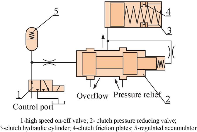
Figure 1 Diagram of clutch electro-hydraulic shift circuit.
At present, foreign countries have improved the structure of high-speed on-off valve electromagnets, including the Helenoid and Colenoid electromagnets of Britain [6, 7], the US Ford ring multi-stage E-type electromagnets [8, 9], the E-type laminated electromagnets of Japan [10], the Disole electro-magnets of Japan [11], etc. From the perspectives of increasing the magnetized area of moving parts, reducing the weight of the armature, selecting high-saturation magnetic induction materials, and designing the structure of “easy magnetic”, the scholars have improved the response speed of the electromagnetic force and the armature, and the response time can be shortened to about 1ms. Compared with foreign countries, the dynamic response time of most domestic engineering vehicles with high-speed on-off valves can be 510 ms, and the type is poor [12–14]. After consulting the literature, the existing research on the optimization design of high-speed on-off valve electromagnets is mostly based on the theoretical formula of common electromagnet design, magnetic circuit segmentation method, etc. [15, 16]. It should be emphasized that the high-speed on-off valve electromagnet and the valve body have strong nonlinearity, so that the dynamic characteristics of the valve strongly depend on the structural parameters of the electromagnet (guide sleeve thickness, yoke thickness, outer casing thickness, magnetic separation angle, magnetic separation position, armature diameter, etc.) and coil parameters (number of strands). However, some of the structural parameters are not necessarily the optimal values in the empirical formula. It is also necessary to use the finite element method to perform secondary analysis and optimization based on different indicators.
In this paper, the initial calculation and verification of the electromagnet theory were carried out using the electromagnet design theory, and the initial electromagnet theoretical model is built. Then the electromagnet parameter model was established in the finite element software ANSYS Electronics, and the static magnetic field and transient magnetic field were simulated and optimized. By analyzing different structural parameters (guide sleeve thickness, yoke thickness, magnetic separation angle, magnetic separation length, armature length) and coil parameters (number of branches and turns), the optimal structural parameter values based on the shortest response time are obtained. A high-speed electromagnet with magnetic isolation is designed. The magnetically separated solid electromagnet sample was designed and processed, and static and dynamic characteristics experiments were carried out to verify the feasibility of the design of the high-resistance electromagnet and the rationality of the simulation.
2 Structural Design of Electromagnet for High Speed On-off Valve
2.1 Structural Design and Material Selection of Electromag-Net for High-speed On-off Valve
In the clutch electro-hydraulic shifting system of the construction vehicle, the high-speed on-off valves output pressure oil to control clutch valve opening degree, and its dynamic characteristics greatly affect the quality of the shift process. The response time requirement of designed high-speed on-off valve is less than 5 ms, driven by a solenoid-type electromagnet, and the recovery method relies on oil hydraulic pressure to recover.
The design specifications for high-speed switching valve electromagnets are as follows:
1. Using conventional PWM control, the voltage value is 24 V;
2. According to the control port flow and pressure demand, determine the working air gap of the armature is 0.3 mm, and the air travel is 1 mm;
3. The designed high-speed on-off valve is a normally open ball valve. When the electromagnet is de-energized, the ball valve core is driven by the oil supply pressure. After preliminary calculation, the electromagnetic attraction of the armature under the initial air gap should be greater than 15N;
4. The ambient temperature of the designed valve is about 40C, and the coil is allowed to rise to 120C.
The schematic diagram of the high-speed switching valve electromagnet is shown in Figure 2. It is mainly composed of armature push rod 1, upper magnetic yoke 2, shell and lower magnetic yoke 3, fixed end cover 4, rear plug sleeve 5, rear plug core 6, pole shoe 7, bolt 8, coil skeleton 9, double coil 10, guide sleeve 11, limit plate 12, magnetic isolation ring 13, armature 14 and sealing ring 15. One end of the armature putter 1 is threaded with the armature, and the other end acts on the ball valve core.
According to the existing soft magnetic materials in China and abroad, the internal magnetic conductive material of the electromagnet is determined to be industrial pure iron DT4 with high saturation magnetic induction strength. The magnetic isolation ring, the rear blocking core, the rear blocking sleeve and the fixed end cover are austenitic stainless steel 316. The coil frame material is epoxy phenolic glass cloth, and the limit piece is made of copper H62.
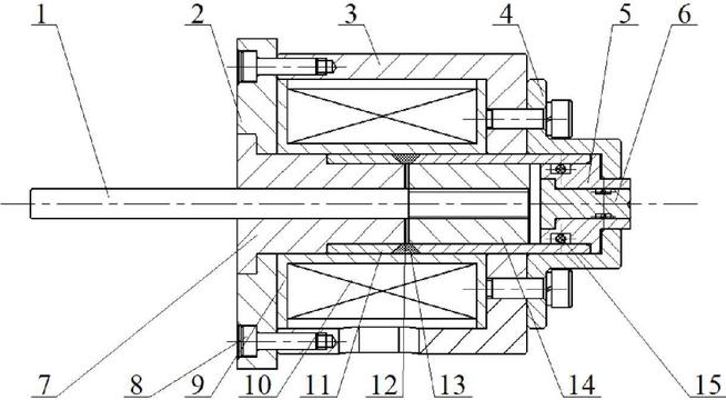
Figure 2 Schematic diagram of high speed switch valve electromagnet.
2.2 Parameter Design of the Initial Structure of the Electromagnet
American scholar Roters proposed the “structural factor” method for the optimal design of electromagnets: when the electromagnet is in the initial working air gap, the steady-state electromagnetic attraction and the air gap magnetic induction meet the following formula [15]:
| (1) |
where is the initial working air gap position electromagnetic force, N; is the working air gap length, mm.
By substituting the above conditions, can be obtained, and the air gap magnetic induction intensity can be estimated from the curve in the electromagnetic design theory.
The steady-state electromagnetic suction can be expressed as [15]:
| (2) |
where is the sum of the length of the working air gap and the limiting piece, mm; is the effective diameter of the armature, mm. Under the above conditions, the value is 7.4 mm.
Considering the magnetic pressure drop outside the non-operating air gap, the magnetic potential can be expressed as:
| (3) |
where represents the magnetic pressure drop at the working air gap, A.
The magnetic resistance, armature diameter and working air gap meet the following formula:
| (4) |
By combining Equations (3) and (4), the total magnetic potential of the magnetic circuit can be obtained as 441A.
The length of the coil is determined by the heating equation of the coil:
| (5) |
where represents the heat dissipation coefficient of the coil, W/cm C; represents the duty cycle; represents the coil width, mm; represents the coil length, mm; and represents the filling factor, and it can be obtained as 19 mm.
The cross-sectional area of a single copper wire is obtained from the voltage equation:
| (6) |
where is the average coil diameter, mm; is the coil voltage, V; is the coil resistance, ; is the resistivity, .
The cross-sectional diameter of the wire can be determined based on the cross-sectional area of the wire:
| (7) |
By combining (5) and (6), the diameter of the copper cross section of a single wire is 0.19 mm. With reference to the enameled wire standard, the diameter of the enameled wire is mm. The coil turns can be estimated from the coil length, width and enameled wire diameter:
| (8) |
From the above conditions, the initial number of turns is 2080 turns.
The coil resistance is obtained from:
| (9) |
The calculated resistance is 110 .
From the above conditions, the initial number of turns is 2080 turns.
Then check the temperature rise of the solenoid coil:
| (10) |
In the formula, represents the heat dissipation area of the coil, mm; represents the allowable temperature rise, C. The verified temperature rise is 111.4C, which is within the allowable temperature rise range. The initial structural parameters of the high-speed on-off valve electromagnet can be obtained from the design of the electromagnet theory as shown in Table 1.
Table 1 Table of structural parameters of electromagnet
| Parameters | Values | Unit |
| Armature diameter | 8 | mm |
| Coil outer diameter | 23 | mm |
| Coil inner diameter | 12.4 | mm |
| Wire section diameter | 0.19 | mm |
| Enameled wire diameter | 0.22 | mm |
| Coil length | 19.0 | mm |
| Coil width | 5.3 | mm |
| Number of coil turns N | 2080 | tr |
The above calculation results preliminarily determined the structural parameters and coil parameters of the high-speed on-off valve electromagnet, and checked the coil temperature rise. However, the guide sleeve thickness, armature length, magnetic isolation structure, and the number of coils are just empirical ranges, and their effects on the static electromagnetic force and the armature transient displacement characteristics cannot be accurately reflected. Therefore, finite element software is needed to analyze the static and dynamic magnetic fields of electromagnets. Find the optimal structural and working parameter values based on the shortest response time.
3 Electromagnetic Simulation and Optimization of Electromagnets
In order to obtain greater armature motion acceleration and shorten the response time of the electromagnet, on the one hand, it is necessary to obtain an increase in electromagnetic force under the same volume conditions to ensure a large moving speed; on the other hand, it is necessary to analyze the transient excitation process of the armature. Therefore, based on the finite element software ANSYS Electronics, a simulation model of the static magnetic field and the transient magnetic field of the electromagnet is established. The analysis and optimization of the structural parameters and working parameters are based on the improvement of the static electromagnetic force and the reduction of the armature dynamic response time, and the final structural parameters of the electromagnet are determined.
3.1 Simulation and Analysis of Static Magnetic Field of Electromagnet
When modeling a static electromagnet, the vector magnetic potential A is defined to satisfy the following formula:
| (11) |
In the formula, represents the Z-axis component of the vector magnetic potential, ; represents the current density of the current flowing section, ; represents relative permeability, H/m; represents vacuum permeability, H/m.
To get the coil inductance matrix, the magnetic field energy needs to be analyzed:
| (12) |
In the formula, represents the magnetic field energy, J; represents the current,A; represents the magnetic induction intensity at that moment, T; represents the magnetic field intensity at the moment, A/m.
The static electromagnetic force is expressed by the principle of virtual work:
| (13) |
In the formula, represents the energy storage of the magnetic field of the system, J; represents the current establishing the magnetic field, and A; represents the total displacement in the direction of movement, mm.
Considering that the structure of the electromagnet can be regarded as an axisymmetric model, a two-dimensional simulation module is selected in order to effectively shorten the simulation time without changing the simulation accuracy. The material properties that define each structure are shown in Table 2 and substituted into the magnetization curve of industrial pure iron DT4. Selected current source excitation and balloon boundary conditions, IN 441A. Considering the need to continue the transient simulation, combining adaptive meshing and manual meshing, the electromagnet model and meshing are shown in Figure 3. Set the side length of the guide sleeve and the housing unit to 0.3 mm; set the side length of the armature unit to 0.8 mm; set the side length of the coil and yoke unit to 1.5 mm.
Table 2 Table of material properties of electromagnet parts
| Part Name | Material | |
| Armature | DT4 | |
| Bushing | Magnetically permeable part | DT4 |
| Magnetic isolation part | H62 | |
| Shell | DT4 | |
| Yoke | DT4 | |
| Coil | Copper | |
| Coil bobbin | Epoxy phenolic glass cloth | |
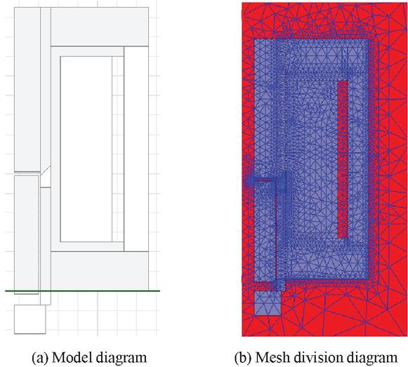
Figure 3 Schematic diagram of high speed switch valve.
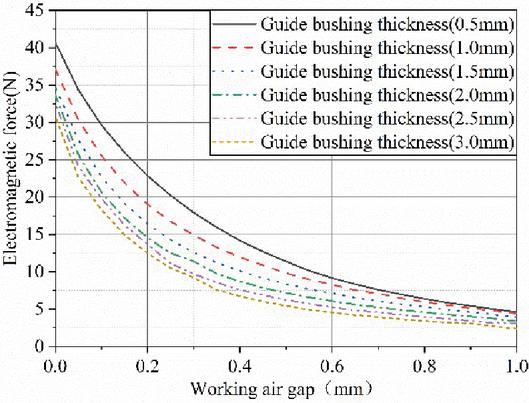
Figure 4 Static electromagnetic force variation of different guide bushing thickness.
3.1.1 Effect of guide bushing thickness on static characteristics
The variation curves of the electromagnetic force of different guide bushing thickness are shown in Figure 4.
It can be seen that when the guide bushing thickness increases, the static electromagnetic force of the moving part decreases. When the armature is in the initial working air gap of 0.3 mm and the thickness of the guide sleeve is 3 mm, the initial electromagnetic force is the smallest, which is 9.22N; when the thickness of the guide sleeve is 0.5 mm, the electromagnetic force is the largest, which is 17.91N. This phenomenon can be analyzed from the magnetic circuit. When the magnetic field line passes through the internal magnetic circuit of the coil, the magnetic path of the suction place is superimposed by the air gap itself and the guide sleeve at the air gap. An increase in the thickness of the guide sleeve results in a decrease in the magnetic flux passing through the air gap, and an increase in the number of magnetic lines of force passing through the guide sleeve, thereby reducing the steady-state electromagnetic force.
3.1.2 Effects of outer magnetic pole thickness on static characteristics
The outer magnetic pole includes an upper magnetic yoke, a lower magnetic yoke and a shell. The effects of different yoke thickness on the electromagnetic force are shown in Figure 5.
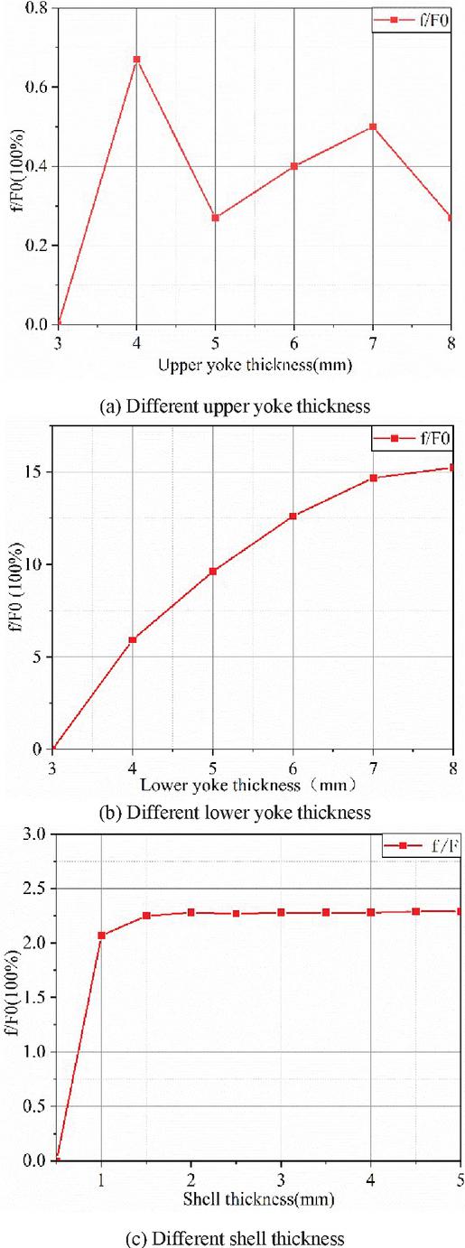
Figure 5 Static electromagnetic force variation of different thickness of outer magnetic pole.
It can be seen from the figure that the increase in the thickness of the upper yoke has an effect of increasing the electromagnetic force less than 1%; the increase in the thickness of the lower yoke has a significant effect on the increase of the electromagnetic force, which can increase about 15%. This phenomenon can be analyzed from the perspective of magnetoresistance. When the thickness is 3 mm, the smaller the cross-sectional area there is, the larger the magnetoresistance will be, and the magnetomotive force will be attenuated and the increase of electromagnetic force will be limited. When the thickness is increased to 7 mm, the magnetoresistance decreases, the magnetomotive force attenuates to a decrease, and the armature moving parts gain more magnetomotive force and the electromagnetic force increases. However, the total magnetic potential is constant, so the electromagnetic force does not increase infinitely with the thickness of the yoke. For the same reason, the thickness of the shell has the same result.
3.1.3 Effects of armature length on static characteristics
The electromagnetic force curve and magnetic flux change of different armature lengths are shown in Figure 6.
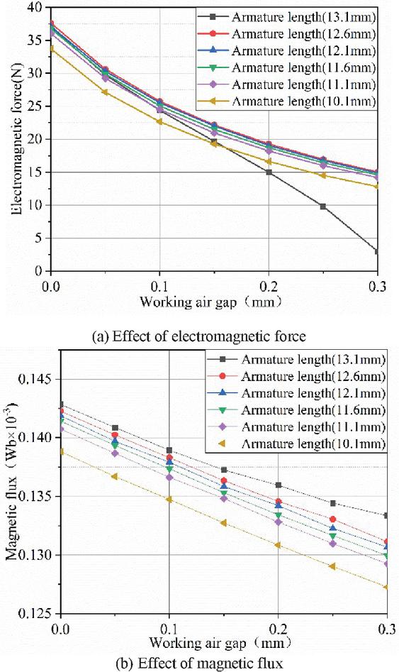
Figure 6 Effects of different armature lengths on static properties.
As the armature length increases, the electromagnetic force increases. Due to the change of the armature length, the air gap at the rear end of the armature appears, which reduces the magnetic resistance in the entire magnetic circuit. When the length is increased, the magnetic resistance decreases and the magnetic flux increases. But the magnetic flux cannot increase indefinitely, the armature length reaches a certain value, and the magnetic flux will tend to a fixed value.
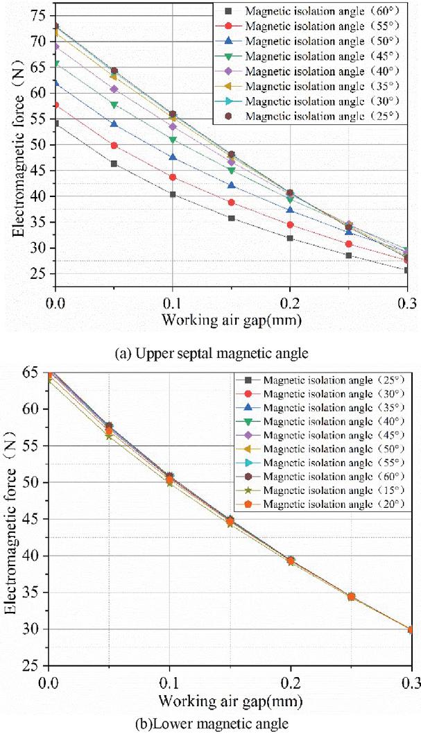
Figure 7 Effects of different magnetic isolation Angle on static characteristics.
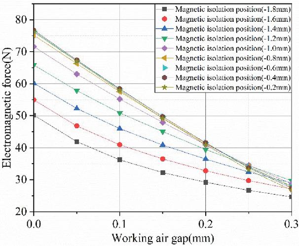
Figure 8 Effects of different magnetic isolation positions on static characteristics.
3.1.4 Effects of magnetic isolation structure on static characteristics
The change curves of electromagnetic force at different magnetic isolation angles and magnetic isolation positions are shown in Figures 7 and 8, respectively.
When the upper magnetic separation angle decreases, the electromagnetic force at the initial position increases first and then decreases, and reaches a maximum value at 45. As the electromagnetic force at the suction point increases, the slope of the electromagnetic force-displacement curve gradually increases. The total electromagnetic force is the vector superposition of the axial force and the radial force. When the angle is 45, the initial position of the radial electromagnetic force reaches the maximum value in the axial component. Therefore, an upper magnetic isolation angle of 45 is determined. This magnetic isolation angle obtains the maximum value of the steady-state electromagnetic force at the initial position, which is beneficial to the armature to move with a large acceleration. The effect of the lower magnetic isolation angle on the electromagnetic force is not as obvious as the upper magnetic isolation angle.
3.2 Simulation and Analysis of Electromagnetic Transient Magnetic Field
The vector magnetic potential A in the dynamic electromagnetic field satisfies:
| (14) |
In the formula, represents the coercive force of the permanent magnet, T; represents the speed of the armature, ; represents the vector magnetic potential, ; represents the true source current density, .
The coil circuit equation of the circuit link:
| (15) |
where is the voltage across the coil, V; is the current, A; is the series resistance of the circuit, ; is the equivalent resistance of the coil, ; is the flux linkage, Wb.
The static electromagnetic force is expressed by the principle of virtual work:
| (16) |
In the formula, represents the mass of the moving part, g; represents the armature displacement, mm; represents the load of the moving part, N; represents the viscous damping coefficient.
Since the armature is displaced by the electromagnetic force, a band motion domain needs to be added to the model. And the armature is always surrounded by the band motion domain in the whole movement process. The material of the motion domain is set to vacuum. When adding excitation, choose to directly add voltage or current, and external circuit control coils can also be set through the Maxwell Circuit module. When setting in the motion domain, it is necessary to set the movement displacement and mass of the moving body. The armature moves forward along the Z axis, and the maximum displacement is 0.29999 mm.
3.2.1 Effects of guide sleeve thickness on transient characteristics
The effects of different guide sleeve thickness on transient characteristics are shown in Figure 9. When the thickness of the guide sleeve is increased from 1 mm to 2 mm, the time consuming increases in the sub-millisecond order. The occurrence of this phenomenon can be analyzed from the perspective of magnetic field lines: the thickness of the guide sleeve does not change much, so the increase in time consumption is relatively small. The number of magnetic lines of force due to magnetic potential is constant, while the guide sleeve and the armature are both magnetically permeable materials and the guide sleeve is located inside the armature. It is closer to the coil so the magnetization effect is higher As its thickness increases, it means that more magnetic lines of force should have been generated inside the armature. However, as the radial distance increases, it enters the guide sleeve, which makes the degree of magnetization of the guide sleeve higher. The degree of magnetization of the armature is reduced, and it can be seen from the current response and the electromagnetic force response that the growth rate becomes slower, thereby increasing the time consuming.
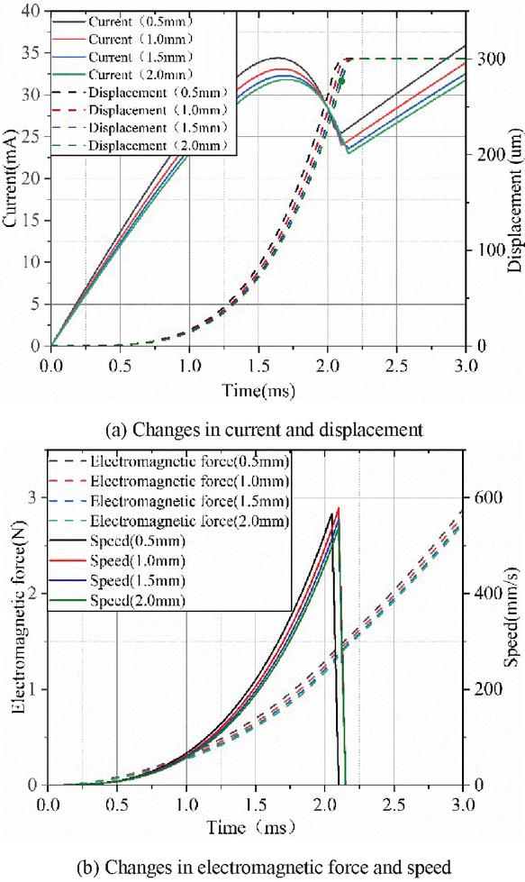
Figure 9 Effects of different guide sleeve thickness on transient characteristics.
3.2.2 Effects of armature length on transient characteristics
The effects of different armature lengths on transient characteristics are shown in Figure 10. When the length is 13.1 mm, the armature pull-in takes 2.25 ms; when the length is 11.6 mm, the time is shortened by 8%. From the perspective of magnetization and dynamics of moving parts, an increase in the degree of magnetization is conducive to the increase of the electromagnetic force and the speed of the current increase, and a reduction in the mass is beneficial to the reduction of the inertial force. Therefore, when the length is shortened from 13.1 mm to 11.6 mm, the non-working air gap is increased by 1.5 mm, but the mass is reduced by 0.5 g. After the two effects are superimposed, the mass reduction plays a leading role, so the time consumption is shortened.
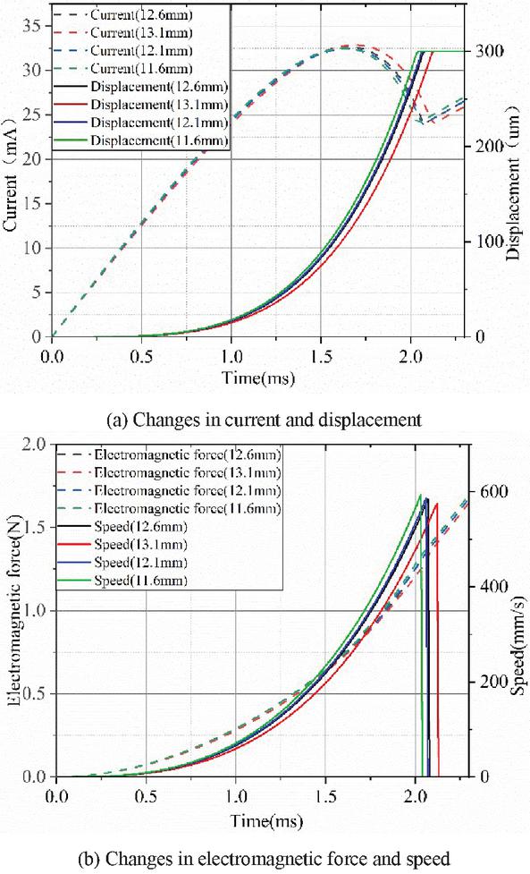
Figure 10 Effects of different armature lengths on transient properties.
3.2.3 Effects of magnetic isolation structure on transient characteristics
Increasing the lower magnetic isolation angle shortens the no-load pull-in time, but the reduction is not consistent. When the angle is increased from 25 to 35, the response time is shortened from 2.67 ms to 2.35 ms, which is a tenth reduction. When it continues to increase, the time consumption is shortened to the sub-millisecond level, and the effect is reduced. The process can be analyzed from the perspective of magnetic field lines. When the angle is small, no effective magnetic circuit is provided for the magnetic field lines to pass through the working gap, and the number of magnetic field lines is not large. As the angle increases, the magnetic lines of force of most of the guide sleeves enter the air gap. It can also be seen from the electromagnetic force response curve that the growth rate increases and the time consumption decreases. However, the total number of magnetic lines of force is constant, so the effect of continuing to provide effective magnetic circuit to improve dynamic characteristics will not increase by the same amount.
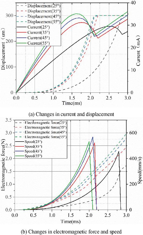
Figure 11 Effects of different magnetic separation angles on transient characteristics.
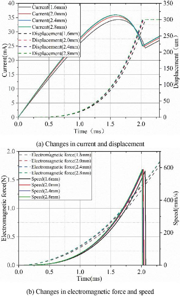
Figure 12 Effects of different magnetic isolation lengths on transient characteristics.
When the length is 1.6 mm, part of the magnetic field lines directly enter the air gap without passing through the armature, so this part of the magnetic field lines does not provide limited magnetic kinetic energy. As the length increases to 2.8 mm, this part of the magnetic field lines are restricted and can only pass through the armature to enter the air gap, which makes the electromagnetic force growth of moving parts increase to a certain extent. However, the number of some magnetic field lines is too small compared with the axial effective magnetic field lines, so the response speed cannot be significantly improved.
3.2.4 Effects of coil strands on transient characteristics
The number of turns is constant, and the effects of different coil strands on transient characteristics are shown in Figure 13. When the number of coils is changed to two, the resistance in the total circuit is reduced to 1/4. It can be seen that the inductance and resistance are also reduced by about 75%. Considering the mutual inductance, the reduction of the inductance is relatively low, and the time constant is basically unchanged. However, since the total resistance is reduced, the stable current is increased. From the response curves of current and electromagnetic force, it can be seen that the growth rate of the two increases significantly. At the time of pull-in, the pull-in current increased from 25 mA to 60 mA. It increased by 1.6 times. And the response time was shortened from 2.01 ms to 1.50 ms, indicating that parallel coils can shorten the response time.
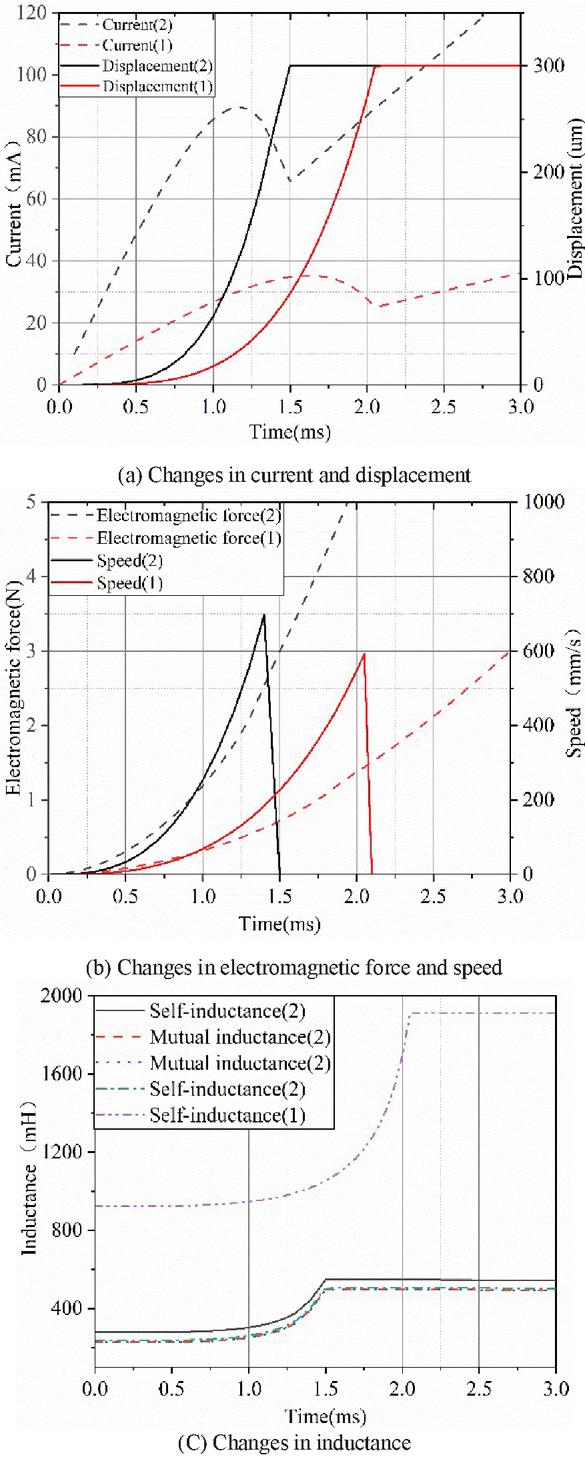
Figure 13 Effects of different winding branches on transient characteristics.
In summary, the structure parameters of electromagnet (thickness of guide sleeve, thickness of outer magnetic pole, length of armature, magnetic isolation structure) and coil parameters (number of strands) are simulated and analyzed. The optimal parameter value based on the shortest response time was determined. As shown in Table 3, a high response magnetically isolated solid electromagnet is obtained.
4 Manufacturing and Testing of Electromagnets
The electromagnet is processed and manufactured, wherein the relevant soft magnetic material is subjected to bright annealing and bluing treatment after the processing is completed to ensure that the internal magnetic characteristics of the soft magnetic material are not affected by the mechanical stress caused by machining. The physical picture of the electromagnet is shown in Figure 14.
Table 3 Table of optimization parameters of electromagnet
| Parameters | Values | Unit | |
| Guide bushing thickness | 1 | mm | |
| Outer magnetic pole thickness | shell | 4 | mm |
| Upper yoke | 3 | mm | |
| Lower yoke | 6 | mm | |
| Armature length | 12.1 | mm | |
| Magnetic isolation structure | Upper septal magnetic angle | 45 | |
| Lower magnetic angle | 55 | ||
| Magnetic isolation length | 1.8 | mm | |
| Coil strands | 2 | ||
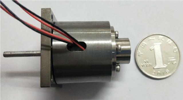
Figure 14 Electromagnet specimen.
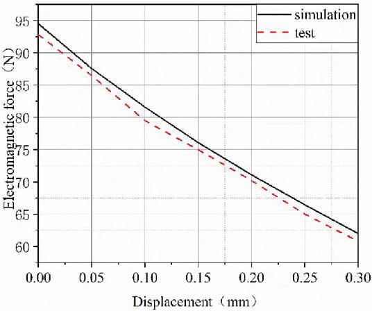
Figure 15 Static electromagnetic force – armature displacement curve of electromagnet.
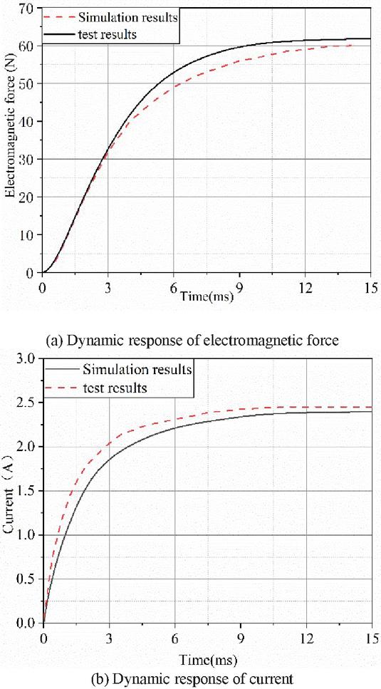
Figure 16 Dynamic electromagnetic force and current response curve of electromagnet.
The static and dynamic characteristics experiments were performed on the above-mentioned electromagnet test pieces. The dynamic electromagnetic force curves when the force-displacement curve and position are unchanged are shown in Figures 15 and 16.
It can be seen from Figure 15 that the steady-state electromagnetic force gradually increases with the decrease of the air gap, and the results obtained from experiments and simulations under the same working air gap conditions are relatively consistent. The electromagnet at the initial air gap position is 60.80N, and the electromagnetic suction at the air gap position of 0.2 mm is 70.20N. The error is within 5%, which verifies the accuracy of the electromagnet simulation model.
5 Conclusion
This paper uses the electromagnet design theory and the finite element software ANSYS Electronics to design the parameter of the high-speed on-off valve electromagnet of the electro-hydraulic gearshift system of the engineering vehicle clutch. It avoids the ambiguity of using only empirical formulas to define parameter range values, which enriches the design method of electromagnets. Aiming at the indicators for improving the static electromagnetic attraction and the dynamic characteristics of the armature, the effects of the structural parameters (the thickness of the guide sleeve, the thickness of the outer magnetic pole, the length of the armature, and the magnetic isolation structure) and the coil parameters (number of strands) on the electromagnetic force and displacement response were analyzed more comprehensively. It is concluded that reducing the thickness of the guide sleeve, increasing the thickness of the outer magnetic pole and the armature length, and increasing the number of coils can effectively improve the initial electromagnetic suction and response speed. There is an optimal value for the magnetic isolation angle and the magnetic isolation position based on the shortest response time. Test pieces of magnetically isolated solid electromagnets were fabricated and tested. The simulations and the experiment results were relatively consistent. The correctness of the simulation model and the feasibility of the design are verified, which provides ideas for the high-speed on-off valve solenoid of the electro-hydraulic shift system of the engineering vehicle clutch.
References
[1] Wang Guanhai, Research on Transmission Control System of Automatic Transmission Mechanism Used in High-power vehicles[D]. Harbin Institute of Technology. 2010.
[2] Sun Chengtong, Ren Haoling. Design and Performance Simulation of Normally Open High Speed Switch Valve Electromagnet[J]. Mechanical Design, 2009, 26(6):10–13.
[3] Wang Huiyi, GAO Bo. Experimental Study on Action Response of Solenoid Valve in Hydraulic Anti-lock Braking System[J]. Hydraulic & Pneumatics, 2001(9):2–4.
[4] Zhao Xinxin. Modeling and shift control of automatic transmission for engineering vehicles [D]. University of Science and Technology Beijing, 2015.
[5] Zhao Keli, Ma Le, Liu Jiyuan. Simulation of Intelligent Shift Schedule of Engineering Vehicles[J]. China Journal of Highway and Transport, 2006, 19(5): 123–126.
[6] Seillyah. Colenoid actuators-further developments in extremely fast acting solenoids[J]. SAE Preprints, 1981 (810462): 1–12.
[7] Seillyah. Helenoid actuators-a new concept in extremely fast acting solenoids[J]. SAE Preprints, 1979(790119):1–10.
[8] Schechtermm. Fast response multipole solenoids[J]. SAE, 1983(820203): 846–857.
[9] Mutaih, Yamasawak. Fundamental operations of a multipolar dis k-solenoid[J]. IEEE T ran sactions on Magnetics, 1995, 31(4):2445–2449.
[10] Shigeikue, Moriyasug, Kojit. Electromagnetic device with stator dis placement regulation: US, 5939811 [P]. 1999-08-17.
[11] Takeuchik, Shimizum, Okazakik, et al. Fast actuator modeling by finite element method[J]. IEEE Transactions on Magnetics, 1994, 30(6):4284–4286.
[12] Zhao Jinsong, Zhang Chuanbi, Zhao Zining, Wang Zhipeng, Yao Jing. Static and Dynamic Characteristics of High Speed Switch Digital Valves[J]. China Mechanical Engineering, 2018, 29(02): 145–150157.
[13] Li Paixia, Zhang Xiaojun, Liu Keming. Research on Characteristics of High Speed On-Off Valve Based on Double Voltage Drive[J]. Hydraulic & Pneumatic, 2018(07):59–64.
[14] Liu Xiangyang, Nie Songlin, Li Guanghui. Dynamic Characteristics of Hydraulic Direct Drive High Speed Switch Valve[J]. Journal of Beijing Polytechnic University, 2017, 43(07):1051–1059.
[15] Zhang Guansheng, Lu Yiguo Tong. Electromagnets and Automatic Electromagnetic Elements [M]. Mechanical Industry Press, 1982.
[16] Huang Weigang, Wang Xuyong, Wang Xianzheng, Zhong Tingxiu. Study on the Mechanism of Switching Characteristics of High Speed Solenoid Switch Valve[J]. Journal of Shanghai Jiaotong University, 1998(12):40–43.
Footnotes
*Basic Product Innovation Plan for Vehicle Power Scientific Research Project (JCCPCX201704).
Biographies

Qingjun Yang received his Ph.D., M.S. and B.S. degrees in mechatronics engineering from Harbin Institute of Technology, China, in 1995, 1997 and 2003, respectively. He has been with the mechatronics engineering at Harbin Institute of Technology since 2003 and promoted to the rank of associate professor in 2006. His research interests include fluid control and flow field analysis, hydraulic and pneumatic components design, nonlinear control and adaptive control.

Yudong Liu received his M.S. degree in mechatronics engineering from Harbin Institute of Technology, China, in 2019, and received his B.S. degrees in mechanical engineering from Yanshan University, China, in 2017. He is currently pursuing a Ph.D. degree in mechatronics engineering from Harbin Institute of Technology. His research interests include hydraulic components and systems and electro-hydraulic control.

Rui Zhu received his B.S. degree in mechanical engineering from Taiyuan University of Technology, China, in 2017. He is currently pursuing a Ph.D. degree in mechatronics engineering from Harbin Institute of Technology, China. His research interests include quadruped robot, electrohydraulic servo control and nonlinear control.

Qi Mao received his B.S. degree in mechanical engineering from Taiyuan University of Technology, China, in 2018. He is currently pursuing a Ph.D. degree in mechatronics engineering from Harbin Institute of Technology, China. His research interests include heat and mass transfer and microfluidic technology.

Rizhi Dong received his M.S. degree in mechatronics engineering from Northeast Petroleum University, China, in 2018. He is currently pursuing a Ph.D. degree in mechatronics engineering from Harbin Institute of Technology. His research interests include artificial photosynthesis and pipeline vibration.

Hongxuan Jiang received his M.S. degree in mechatronics engineering from Harbin Institute of Technology, China, in 2018. He is currently a researcher at the Transmission Technology Department of the North China Vehicle Research Institute. His research interests include hydraulic systems and electro-hydraulic control.
International Journal of Fluid Power, Vol. 24_1, 29–58.
doi: 10.13052/ijfp1439-9776.2412
© 2023 River Publishers