Virtual Design and Analysis of the Balancing Element of an External Gear Machine Considering Cavitation and Mixed Lubrication Effects
Thomas Ransegnola* and Andrea Vacca
Maha Fluid Power Research Center, Purdue University, West Lafayette, IN USA
E-mail: transegn@purdue.edu; avacca@purdue.edu
*Corresponding Author
Received 09 June 2022; Accepted 21 July 2022; Publication 17 January 2023
Abstract
This paper presents a simulation based approach for sizing the axial balance elements of a pressure compensated external gear machine. The reference hydraulic unit must be able to guarantee operation in two quadrants, as either a pump or a motor. It also needs to operate in a wide operating range of speed and pressure, as it is to be used as primary hydraulic unit for an electro-hydraulic actuator (EHA). The design procedure builds upon past work at the author’s center, but it extends it to the case of multiple quadrant units. Also, a unique method for modeling of both mixed lubrication and cavitation that might occur in the lubricating film is used. After describing the design procedure, the paper discusses the features of the balancing of a reference unit, along with the effects of both cavitation and mixed lubrication.
Keywords: External gear machines, lubricating interface design, cavitation, mixed lubrication.
1 Introduction
In high pressure external gear machines (EGMs), the design of the hydrodynamic balancing elements that seal the lubricating gap at the lateral surfaces of the gears is a determining factor for both the efficiency and durability of the unit. Figure 1(a) shows the pressure compensated external gear machine taken as reference in this work, with its main parameters given in Table 1. The machine is designed for use in an electro-hydraulic actuator (EHA), requiring 2-quadrant operation. This is accomplished, as is shown in Figure 1(b), with a directional control valve connecting the outlet of the EGM to high pressure from either chamber of the linear actuator. Motoring and pumping modes are accomplished by changing the direction of rotation of the electric machine. In order to increase the efficiency of the electric machine, the EGM must operate over a wide range of speeds to meet its flow demands. Since the unit must also accomplish fine control of the actuator at low operating speeds, needle bearings are used in place of the journal bearings which are common in these units. With the choice of needle bearings, a lateral balancing plate is selected in this design, with the bearings housed in the body of the pump to decouple the two interfaces.
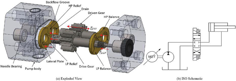
Figure 1 Reference external gear machine for present work (a) exploded view (b) 2-quadrant ISO circuit.
Table 1 Reference EGM details
| Feature | Value |
| Number of teeth | 12 |
| Displacement | 10.69 cc/rev |
| Operating Pressure | 0 – 210 bar |
| Operating Speed | 6000 – 4500 rev/min |
In pumping mode, power is given as input to the machine via the drive shaft from the electric motor, which realizes a displacing action of the volumes of fluid trapped between the teeth of the meshing gears (TSVs). In doing so, high pressure fluid is delivered to outlet. In motoring mode, the shaft rotates in the opposite direction, and instead the pressurized fluid returns power to the same prime mover, acting as an electric generator, as the pressurized fluid is expanded. In either condition, excess leakage is possible in the gap between the lateral balancing element and the gear face due to the high operating pressures. A properly designed balance area controls this leakage by maintaining a thin hydrodynamic film. In this case, a lateral plate is used, and needle bearings mounting in the pump body bear radial loads. The lubricating film should also avoid instances of contact between the gears and the compensating plates. This would lead to wear and excessive torque loss. Since radial loads of the unit are carried by needle bearings, the lateral plate of the unit is free to move axially subject only to the balance of pressure between the hydrostatic ‘balance’ and hydrodynamic ‘gap’ sides of the plate. It is also common, though, for a thicker bearing block to be used in place of the plate with bearings housed within its body. The present work is equally applicable to this configuration.
Due to the complexity of their working principle, these balancing elements are often designed using simplified approaches, which provide only limited information to the designer. These often include approximating or neglecting hydrodynamic effects, and refining the design through trial and error processes. In previous works, effort has been made to develop more effective tools to support these procedures. In [1], Borghi et al. performed a detailed study of the pressure distribution of the plate in both parallel and tilted configurations. Similar analyses have been performed both numerically [2] and experimentally [3], and confirm that in fact the tilting of the bushing has a strong impact on the lubricating film performance.
The issue, however, is that the dynamic effects of the plate were not considered in these approaches. In [4], Dhar and Vacca demonstrated that the inclusion of these dynamics had a noticeable effect on the resulting film performance, especially as pertained to the hydrodynamic behavior and equilibrium position of the plate. The model was then extended in [5] by the same authors to consider not only the dynamics of the rigid body, but also the effects of fluid-structure-thermal effects. Consideration of these effects deforms the surfaces of the film, leading to additional wedge geometry that further changes the pressure distribution.
If the combination of these effects is not sufficient to maintain a fluid film, the gap height can decrease to the same order of magnitude as the surface roughness of the bodies. In this case, Thiagarajan and Vacca [6] showed that the inclusion of the surface asperities in the film modeling allowed for agreement with experimental measurement of film leakage, even where a full film model failed. Finally, the same authors showed in [7] that the inclusion of cavitation modeling in films further changed the leakage flow over the gap.
The limitations of these previous works is that they focused on either detailed modeling of a given design, or high level understanding of the design procedure with simplifications. More specifically, they focus only on a single quadrant of operation, and a given balance geometry. While cavitation has been addressed in the films, its modeling has been performed using only simple models including pressure saturation and Elrod [8] approaches. This paper overcomes these limitations by developing a simulation driven design strategy for the balancing element of an external gear machine, which for the first time considers detailed evaluation of the resulting cavitation and mixed lubrication and its effect on the film performance. The result is a design that performs well not only in the nominal condition, but minimizes the presence of asperity contact or cavitation occurring in the dynamics of the operation over the wide range of operating conditions required for use as an EHA. As a result, confidence in the feasibility of the design can be gained before entering the prototyping phase.
2 Modeling Approach
This section describes the model approach taken. In Figure 2, the approach is summarized with the interaction of the various models of the solver. Here, the displacement chamber pressures are solved, and used as boundary condition for the lateral gap film. Based on these forces and pressures, the film pressure and position is solved, with flow returned to the TSV solver. The deformation that results from the pressure solution is accounted for in the deformation module. Finally, the net gap distribution owing to both the rigid body displacement and deformation are used by the asperity module to consider asperity contributions. In the remainder of this section, each module of the solver is discussed.
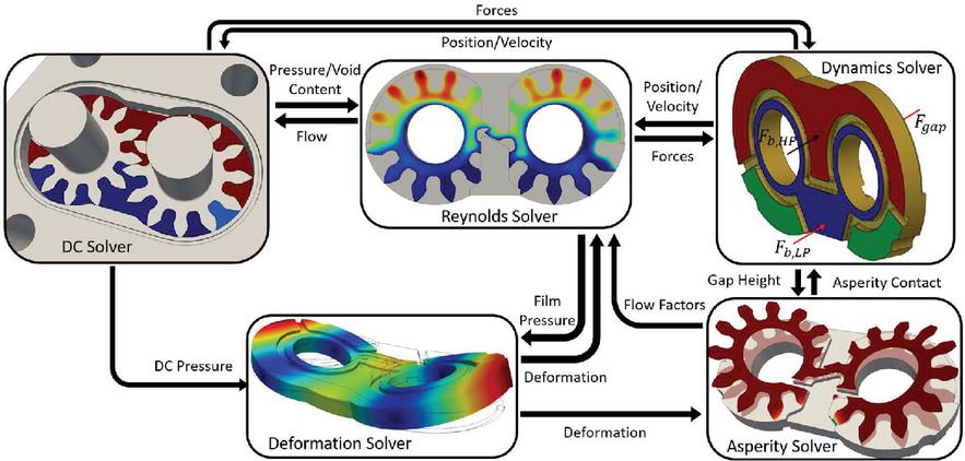
Figure 2 Integrated displacement chamber – film solver approach.
2.1 Universal Reynolds Equation
First, the universal Reynolds equation derived in [9] is briefly demonstrated here. The reader is encourage to refer to [9] for a more detailed derivation. This equation is applied here to the lateral lubricating interface of an external gear machine. To do so, a bulk fluid is first defined, assumed to be a homogenous mixture of the working fluid and its trapped gas. This approach has been successfully applied both the modeling of positive displacement machines [10] as well as lumped parameter systems in general in commercial software such as Simcenter Amesim [11]. Above the saturation pressure of the trapped gas in the working fluid, the bulk fluid behaves in the same way as the working fluid. In this condition, the gas contributes only a negligible mass to the bulk fluid, with no impact on the volume and therefore density. In the present work, the properties of the working fluid above saturation pressure are defined using tabulated values for the fluid used by the machine. Below this saturation pressure, the working fluid cannot retain all trapped gas, and the excess is assumed to be immediately released. In this condition, the density of the bulk fluid is reduced, varying with pressure as derived in [12] as
| (1) |
where the instantaneous gas release is determined by Henry’s law .
If the pressure is further reduced to the vapor pressure of the working fluid, it will begin to evaporate. Since the hydraulic oil is a compound of components with varying vapor pressures, the process of evaporation occurs over a narrow range of pressure. In the present work, it is assumed that the mass fraction of liquid that has evaporated at a given pressure varies linear within this range and the density in this region is
| (2) |
In the work of [9], these relationships were inverted to express the working pressure of the bulk fluid in terms of the local bulk density. Below the density corresponding to saturation pressure , (1) can be inverted as
| (3) |
Similarly, below the density corresponding to the liquid’s high vapor pressure , (2) can be similarly inverted
| (4) |
where
| (5) | |
| (6) | |
| (7) | |
| (8) |
Finally, if the density falls below the density corresponding to the low vapor pressure , and (4) is appropriately simplified. For this bulk fluid, the effective isothermal bulk modulus is then defined
| (9) |
which can be determined from Equations (3) and (4) for the varying conditions. With this bulk fluid as the working fluid of the machine, Reynolds equation can then be applied to describe the pressure distribution in the thin film formed between the lateral plate and the rotating gears. Starting first with the compressible Reynolds equation
| (10) |
the universal Reynolds equation can be found using (9) to relate the pressure of the bulk fluid to its density
| (11) |
This can then be substituted into (10) to form the universal Reynolds equation
| (12) |
This equation is then implemented to progress the density solution of the film as the machine operates. In order to update the pressure dependent tabulated liquid properties, (3) and (4) are used to find the current pressure. This pressure is then used to update the fluid properties. A similar approach derived by Elrod [8] has proven to match with experimental measurement of various hydrodynamic bearings undergoing cavitation, with implementations by many authors [13–15]. By applying this approach to a continuous fluid property, detailed but efficient modeling of the cavitation in these films is achieved.
2.2 Mixed Lubrication
As was demonstrated in [6], modeling of both the cavitation and mixed lubrication that occurs in film breakdown is required to accurately capture the resulting film flows. Considering this, the same flow model from Patir and Cheng [16, 17] is used. This model is derived used empirical relations, which describe the added flow resistance that the asperities introduce as the film thickness is reduced, as well as the modification of the effective dragged fluid. Since this model was developed for an incompressible lubricant, the derivation must be modified. Though this approach has been used in the past [6], a derivation has never been demonstrated, and is therefore included here. To do so, the flow per unit width derived by [16] is used. For the isotropic roughness assumed in this work, this can be expressed as
| (13) |
where is the expected gap height given by the probability distribution of the roughness in addition to the nominal gap . By conservation of mass, the divergence of this mass flow corresponds to the time rate of change of mass in the volume, and the universal mixed Reynolds equation is recovered
| (14) |
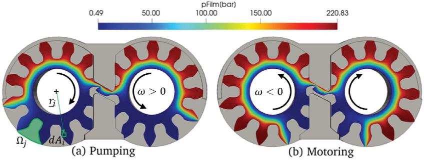
Figure 3 Pressure distribution on gap side’s film of the lateral plate for fixed plate with uniform 3 m gap height at bar (a) puming mode ( rpm) (b) motoring mode ( rpm).
2.3 Rigid Body Dynamics
Aside from updating fluid properties, the film pressures are required to model the dynamics of the floating plate. To capture this, the pressure and shear is integrated over the film to resolve the net force acting on the plate. From the numerical pressure solution, this is accomplished by summing the contribution of each unit element demonstrated in Figure 3
| (15) |
Since the point at which this force acts is not in line with the center of mass of the plate, the moment arm must also be found
| (16) |
This resulting film force, as well as the hydrostatic forces from the TSVs and the balance areas, are then summed to find the net force on the body. These forces are demonstrated in Figure 1, and correspond to the constant pressure regions that the gap pressures must respond to. The constant hydrostatic forces are given by the operating pressure to which they are subjected, and their area as was described in [4]. Any force or moment imbalance leads to linear and angular acceleration of the body as governed by Newton’s 2nd law, which is then integrated to find the time-varying position of the body. The resulting squeezing velocity and gap distribution are then used in the next evaluation of (14).
In regions of low film thickness, the asperities impact not only the flow, but also share the load of the plate as they are deformed. To model this load sharing, the empirical relation derived by Lee and Ren [18] is used to relate the instantaneous gap height to the resulting contact pressure from the asperities
| (17) |
with definition of the directionality and dimensionless hardness of the bodies relating the dimensionless contact pressure to the resulting gap.
Due to the symmetry of the spur external gears of the reference unit, the behavior of the two lateral plates of the machine can assumed to be exactly mirrored. As a result, it is only necessary to solve for the behavior of a single plate. Furthermore, the tilting of the gear can be neglected, due to the absence of any force imbalance in the machine that could lead to a tilting moment.
2.4 Structural Deformation
In response to the pressure distribution over the film, the surfaces of both the plate and gears deform, modifying the gap height distribution. Since this resulting film change then modifies the resulting pressure distribution, this fluid-structure interaction must be considered in simulation.
In the present work, the lateral plate is assumed to be made of an isotropic, elastic material. An inertial-relief constraint is assumed for the plate. Physically, this assumption means that the plate is floating in the unit. As a result, pressures forms on local displacements of the surface as is shown in Figure 2, which also yields a larger scale deflection. Subject to this constraint, mechanical equilibrium of the body is imposed
| (18) |
neglecting body forces and considering surface pressure . Taking advantage of the resulting linearity of the load-displacement relationship, the solution to this problem can be expressed as the superposition of the solutions to a pressure applied in each differential element of the film.
| (19) |
In doing so, the deformation can be solved in a pre-processing step, forming an influence matrix operator which relates a given pressure distribution through the plate to its influence on the surface displacement . This approach is derived in detail in [19].
2.5 Displacement Chamber Pressures
To model the TSV pressures, the simulation tool HYGESim previous developed in [10] is used. This tool is a lumped parameter model, treating each displacement chamber as a lumped control volume with constant properties throughout. The pressure in these volumes is solved using the pressure build-up equation
| (20) |
derived from conservation of mass. Volume flows throughout the unit are modeled with relations that spam from laminar, which is typical of the leakages at tooth tip, to turbulent, typical of the connections in the meshing region. These flows form an interconnected hydraulic circuit which, along with the pressure buildup, are used to describe the main flow and pressure behavior of the TSVs.
The resulting pressures in the TSVs act as boundary conditions for the lubricating interface model. The lateral lubricating interface exchanges fluid with the TSVs via this boundary , capturing the mass flow given in (13) through the film that crosses the boundary
| (21) |
To model the fluid properties in the TSVs, the same tabulated fluid data is used, where again Equations (1) and (2) are used to model cavitation in the TSVs. All required geometric data, included the orifice areas, volume, and boundary shapes are the output of the geometric module derived in [20]. The resulting pressures from the TSVs are applied to both the gears and the plate, acting as an additional load on the gap side of the plate.
3 Design Procedure
With a model capable of evaluating the performance of a given design, usage of the tool will be discussed in this section. The goal of this procedure is to design a balance element of the EGM which can operate over a wide range of pressures and speeds, in both pumping and motoring modes. Over this range, there will be a large variation in the pressure distribution of the film, caused by the superposition of two effects. To ensure that an optimal balance design is identified, operating conditions that span the entirety of the possible range of the unit are taken. The working fluid considered here is a typical ISO VG 46 hydraulic oil, with tabulated fluid properties used to model its behavior.
3.1 Isolation of Hydrostatic and Hydrodynamic
First, the pressures of the TSVs diffuses over the film. For a parallel fixed plate, there is no pressure generation in the film and a hydrostatic pressure develops due only to the diffusion. This is shown in Figure 3 for both a pumping and motoring case. The net force due to this pressure distribution can be resolved into a hydrostatic force, offset from the center of the plate thus inducing a moment. Because of the variation in pressurization of the TSVs over the range of operating conditions, the location and magnitude of this force depend on both speed and operating pressure.
In response to the discrepancy between this hydrostatic force and the opposing hydrostatic force of pressure on the balance side, the plate both tilts and translates. The resulting hydrodynamic wedge that forms, as well as any squeezing motion of the film, drastically changes the film distribution in the lateral gap and the resulting film force. If this hydrodynamic component is not sufficient to mitigate the force or moment imbalance, the plate will make contact with the gears. This leads to wear, decreasing both the life and efficiency of the unit, and must be avoided.
An important observation, though, is that the contact can occur only in response to an excess pressure imbalance between the balance and gap sides of the plate. Thus, the balance design which minimizes the hydrostatic force and moment imbalance will require the least response from the hydrodynamic effects, avoiding the need for mechanical contact. Since the response is hydrodynamic, it is most effective at higher operating speeds. Considering this, priority in design of the hydrostatic balance must be given to the low speed operating conditions, relying on the hydrodynamic effects to carry the resulting imbalance at higher speeds.
The first step of the design procedure, then, is to quantify the hydrostatic force component which, in an ideal design, could be exactly counteracted by the balance areas. To do so, the simulation model is run over the entire operating range of the machine for a constant parallel gap. It is worth noting that in assuming an arbitrary fixed gap height, the resulting pressure distributions can only be treated as approximate. This is because the hydrostatic pressure distribution resulting from a different assumed gap would result in a differing leakage flow impacting the resulting TSV boundary pressures. Considering this, a sufficiently small gap value must be selected which is close to the desired gap. In doing so, the hydrostatic design is optimized to realize this desired gap distribution.
3.2 Hydrostatic Loading
The resulting resolved force and moment are collected at each point, forming a map of the applied load on the plate over its operating range. These maps are given in Figure 4, demonstrating a drastic difference in the plate loading in motoring and pumping mode. From this figure, the effects of operating condition on the required balance force are highlighted. Most notably, there is a drastic change in the loading of the plate when the unit switches between pumping and motoring mode. Within a single quadrant, though, increase in the pressure difference of the unit yields a proportional increase in the gap forces. A change in loading with speed is also observed, with markedly less impact as compared to pressure difference and the sign of the speed. This variation is caused by the differing pressurization behavior of the sealing TSVs.

Figure 4 Resolved hydrostatic loads from gap side due to pressure diffusion (a) axial force (b) tilting moment.
To explain the difference between the two quadrants, Figure 3 shows a typical film result for a pumping and motoring condition. In pumping mode, the high pressure fluid that is displaced by the meshing of the gears is replaced with low pressure fluid from the inlet of the pump. Once the TSV enters the casing, it is isolated from the inlet and intermediate pressure forms. Since there is tight radial sealing in the unit, this pressure is very close to inlet. As a result, pressurization of the TSV occurs as it opens to the backflow groove. This means that around half of the TSVs are at high pressure and apply significant tilting moment on the plate. Instead in motoring mode, the displaced low pressure fluid is replaced with high pressure fluid. As the TSV enters the casing, it is still connected to the backflow groove and therefore maintains its high pressure. Once the TSV leaves the backflow groove, the tight radial sealing does not allow for enough the TSV pressure to drop due to leakage until it opens to the low pressure volume. As a result, a significantly larger area of the unit is at high pressure and applies significantly larger axial force than the pumping mode. Because of the symmetry of this resulting pressure loading about the centerline of the plate, though, a significantly smaller tilting moment results.
3.3 Balance Design
With the loading defined, the next step is to formulate a design which minimizes the hydrostatic force and moment imbalances over the operating range. To do so, the error over all operating points is collected into a single error function
| (22) |

Figure 5 Lateral plate parameterization.
As was discussed above, it is important to give priority to the lower operating speeds, since they rely most on hydrostatic balance. This is accomplished with the inclusion of weight functions for both the moment and force, scaling for the relative importance of each operating point. With an objective defined, the parameterization can then be developed. In Figure 5 the balance side of the lateral plate is demonstrated, including parameters which define the delimiting point between the high and low pressure areas. This delimiter can be seen as the edge of the seal, which is commonly used to isolate the high pressure and low pressure sides. The first parameter , the radius of the seal must be greater than the bore , and less than the outer radius of the plate given by the gear radius . At this radius, the angular span of the high pressure is then determined by the two angles defining the outer and central span of the plate. Notice here that there is an intermediate patch on the low pressure side which is isolated from both inlet and outlet. By connecting this patch to the TSVs, it is set to low pressure in pumping mode and high pressure in motoring mode. This strategy allows for the unique design of the balance for the pumping and motoring modes to overcome the drastic change in TSV pressure distribution. The optimal balance design is then found via a single-objective optimization algorithm.
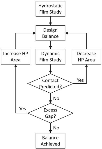
Figure 6 Balance design procedure.
With an optimal design identified, detailed simulation of the dynamic performance of the plate is required to adjust the design. As was stated previous, this is because the imposition of an arbitrary constant gap yields only an approximate pressure solution. Furthermore, the inclusion of deformation induced wedge and squeezing effects change the resulting TSV pressurization and thus the hydrostatic load to be balanced. Considering this, Figure 6 outlines the design procedure used in the present work. The approach begins with an educated initial guess given by the hydrostatic balance. By performing detailed simulations of this initial guess, its performance can be determined. It is likely that this design will suffer from either underbalance yielding excess gap height or overbalance yielding solid contact. Based on the magnitude of this discrepancy, the area can be heuristically adjusted to correct it. Since this can be adjusted in two ways, the choice of parameter to adjust depends on the behavior. If both the pumping and motoring modes exhibit the same imbalance behavior, the central element must be used to adjust the balance area of both configurations. Instead if the discrepancy occurs only in pumping or motoring, and respectively must be adjusted.
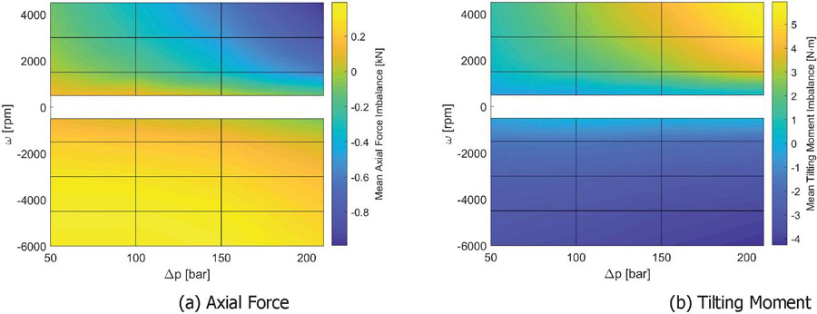
Figure 7 Predicted hydrostatic load imbalance from initial design (a) axial force separating plate and gear (b) tilting moment toward LP.
4 Results
Following the procedure outline above, the initial design is generated using only the hydrostatic loading and is shown in Figure 5. For this design, the predicted load imbalance is shown in Figure 7. This figure demonstrates that by using the intermediate balance area on the balance side, the imbalance in force and moment at low speed can be kept below 200 N and 1 Nm respectively. As the speed is increased, though, the imbalance becomes more noticeable.
In implementation, though, this design leads to a high contact force between the teeth and plate in the high pressure side of the gear. This discrepancy, as mentioned previous, is likely due to the fact that the pressurization is changed as soon as a tilt is introduced. Considering this, the high pressure area is adjusted to allow the high pressure area to reach lower in the plate, decreasing the resulting tilting moment and alleviating this contact. After iterating though the design adjustment phase, the final result is a balance design that maintains low gap height while avoiding contact pressure of all operating conditions considered. An example of this is shown in Figure 8(b), where the gap height remains between 1–3 m over the whole film. Note that this distribution is the net effect over the plate and includes both its rigid tilting as well as the surface deformations of plate and gears. Since this gap is still an order of magnitude above the surface roughness of the surfaces, a full fluid film is maintained. From Figure 8(a) it is demonstrated that the hydrodynamic pressure that develops in the high pressure side is sufficient to carry the load imbalance predicted in Figure 7.
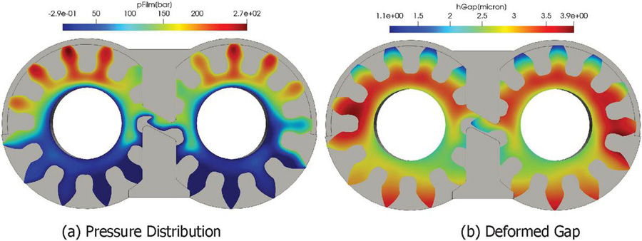
Figure 8 Film solution on gap side’s film of the lateral plate for dynamic plate for bar, rpm (a) pressure distribution (b) deformed gap distribution.
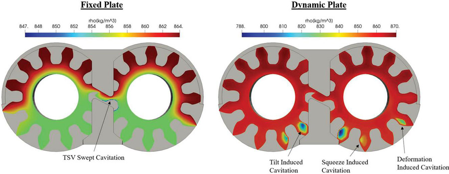
Figure 9 Density distribution on gap side’s film of the lateral plate for fixed and dynamic plate for bar, .
Besides information on the ability of the plate to balance, the use of this tool allows for detailed information on the cavitation tendencies of a given design. An example of this is demonstrated in Figure 9, highlighting various forms of cavitation that occur during operation. Starting first with the static plate case, cavitation can be found in the plate even in the absence of any wedge and squeeze effects. In this case, it is the TSV that undergoes cavitation due to throttling in the meshing zone. Because the gears rotate with respect to the plate, a portion of the cavitated fluid gets dragged into the film. The density of this fluid is low here, so a given volume flow corresponds to a lower mass flow. Furthermore, the bulk modulus is very low for the cavitating fluid, a large amount of mass is required to increase the pressure. As a result, the cavitated fluid gets caught in the film and cannot recover before the next TSV enters the meshing zone. This effect is subtle in the present design, to the point where it cannot be seen in the color scale of the dynamic case. This is because more prominent effects occur here, owing to the resulting wedge geometry which is demonstrated in Figure 8(b). First, the tilting of the rigid body induces a geometric wedge which drops the pressure. A similar effect can be seen due to wedges formed by the deformation of the plate and gears. In either case, the diverging regions that form work to separate the fluid and induces cavitation in response. Finally, consideration of the dynamics of the plate leads to regions that are instantaneously rising. These regions similarly tend to separate the film, which can only fill the void by releasing gas. Notice however that the density changes only slightly to meet these expansions. While local density drop is unavoidable due to the working principle of the balance element, this analysis confirms that the tendency of the film to cavitate is sufficiently small.
5 Conclusion
This paper demonstrated the application of a detailed model of the lateral lubricating interface of an external gear machine for designing the axial compensation system of a two-quadrant pump-motor unit. This analysis considered not only the nominal hydrostatic loads applied on the plate, but also the effects of mixed lubrication and cavitation on the dynamic solution to the film. The design procedure developed here was then demonstrated to identify an ideal design for the given unit over its operating range, with discussion of the resulting film behavior.
Acknowledgement
This material is based upon work partially supported by the U.S. Department of Energy under grant no. DE-EE0008334.
References
[1] M. Borghi, M. Milani, F. Paltrinieri, and B. Zardin, “Studying the axial balance of external gear pumps,” SAE Tech. Pap., no. 724, 2005.
[2] D. Morgridge, H. P. Evans, R. W. Snidle, and M. K. Yates, “A Study of Seal Lubrication in an Aerospace Fuel Gear Pump Including the Effects of Roughness and Mixed Lubrication,” Tribol. Trans., vol. 54, pp. 657–665, 2011.
[3] E. Koç, A. O. Kurban, and C. J. Hooke, “An analysis of the lubrication mechanisms of the bush-type bearings in high pressure pumps,” 1997.
[4] S. Dhar and A. Vacca, “A novel CFD - Axial motion coupled model for the axial balance of lateral bushings in external gear machines,” Simul. Model. Pract. Theory, vol. 26, pp. 60–76, 2012.
[5] S. Dhar and A. Vacca, “A novel FSI-thermal coupled TEHD model and experimental validation through indirect film thickness measurements for the lubricating interface in external gear machines,” Tribol. Int., vol. 82, no. PA, pp. 162–175, 2015.
[6] D. Thiagarajan and A. Vacca, “Mixed Lubrication Effects in the Lateral Lubricating Interfaces of External Gear Machines: Modelling and Experimental Validation,” Energies, vol. 10, no. 1, p. 111, Jan. 2017.
[7] D. Thiagarajan and A. Vacca, “Modelling of the lateral lubricating interfaces in external gear machines considering the effects of cavitation,” in BATH/ASME 2018 Symposium on Fluid Power and Motion Control, FPMC 2018, 2018.
[8] H. G. Elrod, “A Cavitation Algorithm,” J. Lubr. Technol., vol. 103, no. July 1981, pp. 350–354, 1981.
[9] T. Ransegnola, F. Sadeghi, and A. Vacca, “An Efficient Cavitation Model for Compressible Fluid Film Bearings,” Tribol. Trans., p. In Press, 2020.
[10] A. Vacca and M. Guidetti, “Modelling and experimental validation of external spur gear machines for fluid power applications,” Simul. Model. Pract. Theory, vol. 19, no. 9, pp. 2007–2031, 2011.
[11] Siemens, “HYD Advanced Fluid Properties, Technical bulletin 117,” 2017.
[12] P. Casoli, A. Vacca, G. Franzoni, and G. L. Berta, “Modelling of fluid properties in hydraulic positive displacement machines,” Simul. Model. Pract. Theory, vol. 14, no. 8, pp. 1059–1072, 2006.
[13] D. Vijayaraghavan and T. G. Keith, “Development and Evaluation of a Cavitation Algorithm Development and Evaluation of a Cavitation Algorithm,” Tribol. Trans., vol. 32, no. 2, pp. 225–233, 1989.
[14] C. M. Woods and D. E. Brewe, “The Solution of the Elrod Algorithm for a Dynamically Loaded Journal Bearing Using Multigrid Techniques,” J. Tribol., vol. 111, no. 2, p. 302, Apr. 1989.
[15] D. E. Brewe, “Theoretical Modeling of the Vapor Cavitation in Dynamically Loaded Journal Bearings,” J. Tribol., vol. 108, no. 4, pp. 628–637, 1986.
[16] N. Patir and H. S. Cheng, “An Average Flow Model for Determining Effects of Three-Dimensional Roughness on Partial Hydrodynamic Lubrication,” J. Lubr. Technol., vol. 100, no. 1, p. 12, Jan. 1978.
[17] N. Patir and H. S. Cheng, “Application of Average Flow Model to Lubrication Between Rough Sliding Surfaces,” J. Lubr. Technol., vol. 101, no. 2, p. 220, Apr. 1979.
[18] S. C. Lee and N. Ren, “Behavior of elastic-plastic rough surface contacts as affected by surface topography, load, and material hardness,” Tribol. Trans., vol. 39, no. 1, pp. 67–74, 1996.
[19] S. Dhar and A. Vacca, “A fluid structure interaction-EHD model of the lubricating gaps in external gear machines: Formulation and validation,” Tribol. Int., vol. 62, pp. 78–90, 2013.
[20] X. Zhao and A. Vacca, “Numerical analysis of theoretical flow in external gear machines,” Mech. Mach. Theory, vol. 108, no. May 2016, pp. 41–56, 2017.
Biographies

Thomas Ransegnola completed his PhD in 2020 at the Maha Fluid Research Center at Purdue University. His thesis focused on the development of a strongly coupled model of positive displacement machines. He has several journals and conferences publications related to the development and application of this model. He currently works at Sandia National Laboratories, developing multi-physics and linear algebra software. His research focuses on the use of next-generation computing platforms to facilitate simulation of increasingly complex multi-physical phenomenon.

Andrea Vacca earned his Ph.D. from the University of Florence (Italy) in 2005. Before joining Purdue University in 2010, Dr. Vacca was Assistant Professor of Fluid Machinery at the University of Parma (Italy). Fluid power technology has been Dr. Vacca’s major research interest since 2002. Goals of his research are the improvement of energy efficiency, durability, controllability, and noise emissions of fluid power technology. To accomplish these goals, his research team has developed original numerical and experimental techniques for hydraulic systems and components. Prof. Vacca’s interests also include the electrification of hydraulic control systems, and the modeling of the properties of hydraulic fluids, with focus to the effects of aeration and cavitation, as well as the use of low viscous fluids (such as water) in fluid power systems.
Dr. Vacca is the author of more than 200 papers, most of them published in international journals or conferences. He is also active in the fluid power research community. He is chair of Fluid Power Systems and Technology Division (FPST) of ASME, and a former chair of the SAE Fluid Power division. Dr. Vacca is also Treasurer and Secretary of the Board of the Global Fluid Power Society (GFPS). Furthermore, he is also Editor in Chief of the International Journal of Fluid Power and he is in the Editorial Board of Actuators, the Journal of Dynamics and Vibroacoustics and the Journal of Hydromechatronic.
International Journal of Fluid Power, Vol. 24_1, 77–98.
doi: 10.13052/ijfp1439-9776.2414
© 2023 River Publishers