Resonance and Design Constraints in Nacelle-to-Ground Hydrostatic Transmission Concept for Wind Turbines
Henrique Raduenz, Gabriel Linhares Baldo and Victor Juliano De Negri*
Laboratory of Hydraulic and Pneumatic Systems – LASHIP, Department of Mechanical Engineering, Federal University of Santa Catarina – UFSC, Florianópolis, Santa Catarina, Brazil
E-mail: henrique.raduenz@gmail.com; gabriellinharesbaldo@yahoo.com.br; victor.de.negri@ufsc.br
*Corresponding Author
Received 06 April 2023; Accepted 10 May 2024
Abstract
This paper presents design principles for the nacelle-to-ground hydrostatic transmission concept for wind turbines including the analysis of resonance originating from the turbine tower. The design has the pump at the top inside the nacelle and the hydraulic motor at ground level driving the generator that is directly connected to the grid. It has no frequency converter. Resonance can originate from the excitation of the natural frequency of the hydrostatic transmission due to the rotor tower shadow effect. The low natural frequency is a consequence of the large rotor mass moment of inertia and high volume of the pressure lines. Through a non-linear model validated by a prototype, it is shown that the nacelle-to-ground hydrostatic transmission concept can supply electricity to the grid with a frequency error that adheres to regulatory limits. Furthermore, using a simplified model, a procedure is proposed to determine the natural frequency and compare with excitation frequencies. It is shown that resonance does not occur in the region of power delivery to the grid for a meaningful range of mid-size wind turbines. In the case of turbines with a capacity of over 600 kW, the resonance may be present during the power delivery to the grid, which might impose a limit maximum power to this concept. However, other design constraints, such as excessive load loss, pressure surges and availability of hydraulic components, can reduce this maximum power limit. A prototype was built with only off-the-shelf components and served, as shown in this paper, as a proof of concept.
Keywords: Wind turbine, hydrostatic transmission, resonance frequency.
Nomenclature
| Rotor swept area | |
| Generator viscous friction torque coefficient | |
| Power coefficient | |
| Ideal power coefficient | |
| High and low line diameters | |
| Pump volumetric displacement | |
| Motor volumetric displacement | |
| Excitation frequency | |
| Motor to pump height difference (tower height) | |
| Gearbox transmission ratio | |
| Motor and generator mass moment of inertia | |
| Rotor mass moment of inertia | |
| Ratio of the hydraulic line volumes | |
| Damping coefficient | |
| Synchronization torque coefficient | |
| MPT | Maximum Power Tracking controller |
| Rotor mass | |
| Generator rated output power | |
| Generator output power at synchronization | |
| High and low line pressures | |
| Motor inlet and outlet pressures | |
| Pump outlet and inlet pressures | |
| Pump outlet pressure reference | |
| Extracted wind power | |
| Extracted wind rated power | |
| Maximum flow rate | |
| Motor theoretical flow rate | |
| Pump theoretical flow rate | |
| Motor inlet and outlet flow rates | |
| Pump outlet and inlet flow rates | |
| Motor internal leakage | |
| Pump internal leakage | |
| Rotor radius | |
| RRS | Rotor Rated Speed controller |
| SYNC | Synchronization controller |
| Generator electrical torque | |
| Generator electrical torque at operating point | |
| Motor mechanical torque | |
| Pump mechanical torque | |
| Extracted wind torque | |
| Extracted wind torque at maximum efficiency | |
| Generator output voltage | |
| Wind speed | |
| Wind rated speed | |
| Wind speed at synchronization | |
| Fluid speed in the high-pressure line | |
| Fluid speed in the low-pressure line | |
| Maximum blade tip linear speed | |
| High and low line volumes | |
| Hydraulic motor displacement setting | |
| Hydraulic fluid effective bulk modulus | |
| Change in the generator rotor torque angle | |
| Maximum pressure difference at the pump | |
| Pressure drop in high pressure line | |
| Generator efficiency | |
| Motor global efficiency | |
| Motor mechanical and volumetric efficiencies | |
| Pump global efficiency | |
| , | Pump mechanical and volumetric efficiencies |
| Rotor mechanical efficiency | |
| Maximum electric motor angular speed | |
| Generator rated angular speed | |
| Hydrostatic transmission natural frequency | |
| Hydraulic motor and generator angular speed | |
| Generator rated angular speed | |
| Rotor angular speed | |
| Rotor rated angular speed | |
| Rotor angular speed at synchronization |
1 Introduction
Wind turbines operate at rated power that ranges from a few kilowatts to megawatts. Currently, for all power classes, the common solution for connecting the rotor to the generator is through a mechanical coupling, either directly or via a gearbox. However, despite being the typical solution, there are some drawbacks to adopting this approach. In the case of a synchronous generator with a direct connection to a fixed-frequency grid, the torque fluctuations from the rotor cause high dynamic loads on the mechanical components and fluctuations in the power output [1]. In the case of variable-speed operation, a frequency converter between the variable speed generator and the grid is required in order to decouple the generator speed from the grid frequency [1–3]. In the case of transmission with a gearbox, its maintenance leads to a longer downtime [4, 5]. In the case of direct mechanical transmission, also called direct drive, the elimination of the gearbox is an advantage [3]. However, a generator with a large number of poles is required, which results in size and weight constraints in the design of large generators. These can be reduced with the use of permanent magnet generators, but the cost of rare earth materials is still a drawback [1].
An alternative to mechanical coupling that has been investigated in the past decades is hydrostatic transmission. For variable-speed wind turbines, the variable transmission ratio allows the rotor to operate with maximum aerodynamic efficiency and the use of a synchronous generator directly connected to the grid, where a frequency converter is not required. Figure 1 shows the concept of hydrostatic transmission for wind turbines with the generator at ground level.
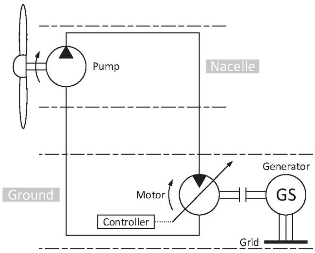
Figure 1 Wind turbine concept with hydrostatic transmission.
A reduction in torsional vibrations from the rotor takes place due to the damping characteristics of the fluid power transmission, increasing the power quality and reducing component wear and consequently the need for maintenance [6].
Most research related to hydrostatic transmissions for wind turbines are focused on increasing the system efficiency through the development of new control strategies, new architectures, and specifically developed hydraulic components. Effort is also being directed toward demonstrating the feasibility of concepts, achieving power scalability, improving the quality of generated power, increasing the annual energy production, and reducing system costs through less maintenance requirements and lower nacelle mass. Studies that are relevant to the issues addressed in this paper are discussed below.
Hydrostatic transmissions can theoretically be scaled according to the turbine power. However, hydraulic components for the megawatt-class are not commonly available in the market and require specific development. According to [7], off-the-shelf components would only be practical for turbines with nominal power up to around 500 kW. The main challenge is to find off-the-shelf pumps with variable and high volumetric displacement that operate at low speed and with high volumetric efficiency. One solution with components available in the market is to use low speed hydraulic motors as pumps (e.g., Hägglunds motors from Bosch Rexroth [8]). However, operating a motor as a pump could still result in low efficiency. Therefore, for high power classes it is necessary to develop components to meet the power requirement unless modular architectures or switchable/digital transmissions are used, as described in [4] and [9].
The authors of [9] used a morphological matrix to generate concepts of hydrostatic transmissions for wind turbines in the very beginning of the design process. The authors concluded that the most promising concept was that with switchable fixed displacement pumps and variable displacement motors. This increases the range of possible transmission ratios between input and output. A similar solution, called the ‘digital hydrostatic drivetrain’ is proposed in [10] for a 2.5 MW turbine. By combining pumps and motors of different sizes, determined by a digital encoding scheme, the authors obtained a transmission using standard components. Through simulation studies the authors shown that it is possible to increase the partial load efficiency of the transmission by only operating with the number of generators required for the power production for that given wind speed. This reduces the number of generators operating at partial load.
The authors of [11] deal with the development of a hydrostatic transmission and test-rig for large-scale wind turbines. Most of the focus is on the development of pumps and motors using Digital Displacement technology. The authors discuss the feasibility and capacity of the design in controlling the variable-speed rotor to its optimal operation point and, consequently, in maintaining the synchronous generator at constant speed. The system is also analysed for synchronization and the delivery of generated power to the grid. It can be observed that substantial component development effort is required to achieve a technically feasible solution. Steady-state experimental results in the laboratory showed efficiency of 91% at maximum power, but expecting it to reach 93% in an operating system. Not surprisingly, the success of the concept has led to further development of a transmission for an even higher power class.
Reference [12] describes the development of a large capacity hydrostatic transmission, also using the Digital Displacement§technology, and presents experimental results. Those obtained from a 7 MW hydrostatic transmission (7 MW pump and two 3.5 MW motors) in a test bed show the operational feasibility of the pump and motor design for a megawatt-class wind turbine application, at least as far as synchronization and achieving rated power are concerned.
Along with the advantage of modular design and the power scalability of hydrostatic transmissions, the continuously variable transmission ratio between input and output allows the rotational frequency of the generator to be kept constant for variable wind conditions [11]. This characteristic allows the elimination of the frequency converter between the synchronous generator and the grid. Therefore, the rotor speed tracks the wind speed for maximum aerodynamic efficiency while the generator can be optimized for operation at constant speed. These aspects are supported by other authors such as [9, 13–15], and [16], where a small-scale test bench was used to evaluate a hydrostatic transmission assuming that all components are located in the nacelle.
Regarding the characteristics of the connection with the grid, with changes in the wind input, the authors in [17] compared the variation of the generator speed driven by a hydrostatic transmission or by a mechanical transmission. Large changes would affect the quality of the generated energy. On comparing experimental results from the hydrostatic transmission test bench with simulation results for the mechanical transmission, the results indicate a lower variation in the generator speed for the hydrostatic transmission. This is a consequence of damping and the variable speed ratio of hydrostatic transmissions.
In terms of different designs that result in a variable transmission, Ref. [18] used a hydrostatic transmission with fixed pump and variable motor. Through simulation results the authors demonstrated the concept feasibility. However, the model does not describe the connection of the generator to the grid. Ref. [19] describes a study on the same architecture and presents modelling and experimental results using an experimental setup to represent a virtual turbine with all components installed in the nacelle. In contrast, Ref. [4] describes a concept with a variable displacement pump and fixed displacement motor, which results in a similar capability of variable transmission ratio. These three references highlight the flexibility of the hydrostatic transmission with respect to the different numbers of architectures that can be designed to meet the application requirements.
There are two approaches to addressing the spatial distribution of components along the turbine. One follows traditional wind turbine drivetrains, where all the drivetrain components are placed inside the nacelle. The other aims for a weight reduction in the nacelle and lower maintenance costs, where the generator and most of components are at ground level. Hydraulic systems enable this architecture due to the possibility of long-distance power transmission through pipelines.
In the megawatt-class, Ref. [20] presented simulation results about the influence of the hydraulic line lengths and component internal leakage on the dynamic behaviour of the turbine. The authors carried out the analysis for a turbine size of 5 MW and for two configurations: one with the pump in the nacelle and the motor at ground level and one with the whole drivetrain in the nacelle. They concluded that when long transmission lines are used, the large fluid inertia becomes relevant for damping turbulent winds, which might improve the system reliability if compared to gearboxes that do not have similar damping capability. The first natural frequency, due to the hydraulic lines, is shifted to lower frequencies with the increased volume of oil. The high fluid inertia introduces a small-time delay in the overall energy transmission which has a higher influence than the friction losses in the dynamic response. Similarly, Ref. [15] states that the low natural frequency of the hydrostatic transmission could be excited by the rotor, however the authors argue that any amplification would be damped. In the present paper, it is shown that it is possible to determine the turbine power range where the low frequencies, resulting from the large rotor inertia and large volumes of oil, are not excited by the rotor frequency.
For offshore applications, Ref. [6] presents the preliminary design of the Delft Offshore Turbine (DOT). In this concept, the pump is in the nacelle and a hydraulic motor at the turbine base drives a seawater pump. The concept explores centralized electricity production, where the pressurized seawater from several turbines is used to drive a single generator. The feasibility of the concept and nacelle mass reduction was demonstrated for a 600 kW rated power turbine prototype, by the authors in [21]. For that particular prototype, a 32% mass reduction was obtained. At the same study, the authors express the concern with stability problems, however not observed in the prototype. A limitation of the study is that the generator was not connected to the grid, as the generated electricity was directly used by the turbine auxiliary systems or dissipated in the brake-resistor.
In [22], the authors estimate significant tower mass savings from removing generator and gearbox from the nacelle, and from the tower itself since now it does not need to support the same mass. Another advantage would be the introduction of energy storage systems at the ground level to support levelling the power deliver to the grid and avoid the transmission of wind fluctuations to the grid.
Technological and economic benefits for offshore wind turbines of replacing the mechanical transmission with a hydrostatic transmission with the generator at base/sea level are addressed in [23]. The authors concluded that around 35% of the nacelle mass can be relocated from the tower to the base. With this new design, average cost savings of 5–24% can be obtained, according to the authors. This is due to a reduction in mainframe material and in the maintenance costs, as well as the removal of the frequency converters. In this way, the technical feasibility demonstrated by other researchers along with these estimated cost savings are motivators to further research on this solution with the generator at the base.
In [24], a simulation study shows the use of accumulator for energy storage and a corresponding control strategy for also a turbine with generator at ground level. The analysed system has a power of 600 kW, similar to the power range studied in the present paper. The authors present results without including the connection with the electrical grid. The model and results are not experimentally validated.
Along with the above-cited researches from several institutes and companies, theoretical and experimental research studies on this topic have been carried out at LASHIP (Laboratory of Hydraulic and Pneumatic Systems at the Federal University of Santa Catarina – UFSC). It was shown through mathematical models that the use of a hydrostatic transmission with a direct connection to the grid is a potential solution [25, 26]. A prototype that explores the concept of having the pump at the nacelle and the motor and generator at the ground, referred to in this paper as the nacelle-to-ground concept was built [27]. The generator is directly connected to the grid using electrical devices developed for hydro-electric power plants. One of the objectives of this research project has been to evaluate the feasibility of using standard components available in the market for this application [7], especially for small power applications. Previous publications by the paper’s authors addressed the development of the model and control strategy [28] and the development of a controller based on rotor speed compensation [29].
A review of applications of hydraulic solutions for pitch and yaw control, brake system, and power transmission in wind turbines is presented in [30]. The conclusions presented follow the publications analyzed above, including the fact that there are a limited number of hydraulic components for high-power systems, mainly low-speed, large-displacement pumps and motors. That review paper also emphasizes the benefits of hydraulics for power transmission, such as the high power/volume ratio, adjustable transmission ratio without the need for a gearbox, and direct connection of the generator to the grid, reducing the need for power electronics. In the same way as reported in other publications discussed in the present paper, installing the generator on the ground benefits with easier maintenance and reduction of mass in the nacelle.
Based also on the publications reported throughout this section, the main disadvantages of placing the hydraulic motor and generator on the ground are the effect of fluid inertia and friction losses due to long transmission lines. This introduces low dynamics into the transmission system, which is considered by some authors to be an advantage and by others a disadvantage. Therefore, complementary studies, mainly including the physical installation with differences in height and connection to the grid, can help in understanding and developing the technology.
It must be pointed that other technical constraints might affect the nacelle-to-ground hydrostatic transmission design. The diameter and length of pipes could make the solution infeasible for high power applications, and would add mass to the system. The hydraulic swivel connection between tower and nacelle to allow the nacelle to track the wind direction needs to be further investigated and would increase weight on the tower. The volume of oil in pipes could cause significant environmental damages in case of external leakage.
In the present paper, the results of modelling, simulation, and operation of a nacelle-to-ground hydrostatic transmission for wind turbines are shown. It includes the full transmission system, from the rotor output (pump input) to the electrical grid. Compared with previous studies on hydrostatic transmissions, the focus is on small size wind turbines with a generator that has an effective and direct connection to the grid instead of other means of emulating the grid load on the system. In this way, one contribution of this paper is to demonstrate, based on simulation and experimental results that this concept can be implemented up to a given power with off-the-shelf components. Along with this, the determination of the hydrostatic transmission natural frequency using a simplified dynamic model is also presented. The accuracy of the model is verified by simulation by comparing it with a detailed non-linear model validated through measurements on a prototype. To verify whether the natural frequency will eventually be close to the turbine excitation frequency induced by the tower shadow effect, the correlation of frequencies with the turbine power is presented. Considering this restriction, the limits for the application of a nacelle-to-ground hydrostatic transmission based on the nominal turbine output power are reached. The approach presented here can be applied to the analysis of different designs and power classes.
The content of this paper is organized as follows: in Section 2 the hydrostatic transmission and its operation are described along with the prototype used for the experimental study. The models used for simulation and the assessment of resonance constraints are detailed in Section 3. Experimental and simulation results for validation of the model and to prove the concept are presented in Section 4. Conclusions drawn from this study are summarized in Section 5.
2 Concept and Prototype of Wind Turbine with Hydrostatic Transmission
The prototype studied in this paper was developed for horizontal-axis variable-speed wind turbines. In these turbines, for a given wind speed, the blades achieve maximum aerodynamic performance for a specific rotor angular speed. Therefore, the turbine control system must continuously adapt to extract the maximum power while delivering energy at constant frequency. These requirements affect the operation, design, and control strategies, as described below.
2.1 Wind Turbine Operation
According to [3], the extracted wind power () is described as
| (1) |
where is the air density, the rotor swept area, the wind speed and the power coefficient.
The power coefficient is the ratio between the extracted power and the available power in the wind. It is a function of the tip speed ratio (), which is expressed by
| (2) |
where is the rotor speed and the rotor radius.
The power coefficient () has a maximum value at a specific value and this varies with the blade design. Therefore, based on Equation (2), to maintain the maximum power coefficient it is necessary to adapt the rotor speed according to the wind speed. The strategy for controlling the rotor speed is different in the turbine operating regions, which are shown in Figure 2.
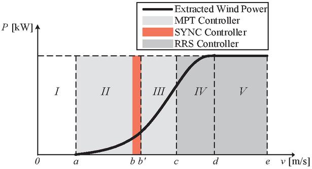
Figure 2 Extracted wind power for the operating regions of a variable-speed wind turbine.
In region the wind is below the minimum speed necessary to drive the rotor. In region the wind speed is sufficient to drive the rotor, however the generator is still disconnected from the grid. In this region, it is necessary to control the rotor speed according to the wind speed to achieve maximum power extraction to drive the generator to the required speed for synchronization and connection to the grid. The synchronization to the grid takes place between wind speeds to still within region . The voltage, frequency, amplitude, and phase of the generator output are matched with the grid before the connection is established. In region the generator is synchronized and delivers energy to the grid. The objective is to track the wind speed to achieve maximum power extraction and generation. In region the system reaches the rated rotor speed, which must be limited to avoid the failure of equipment and/or noise generation above permitted levels. In region the turbine operates at rated rotor speed and rated power. The control operation regions have specific controllers. In Figure 2 they are named according to the active controller: MPT – Maximum Power Tracking Controller; SYNC – Synchronization Controller; RRS – Rotor Rated Speed Controller.
The hydrostatic transmission is able to control the rotor speed in all regions except region , where maximum pressure is achieved. Therefore, blade pitch angle control must be used to limit the power extracted from the wind. The operation conditions in regions to were modelled and implemented in a prototype for proof of concept. In this paper, emphasis is given to the operation in region .
Another topic explored in this study was the hydrostatic transmission resonance that can be present due to excitation originating from the tower shadow effect. The wind right at the front of the turbine tower decelerates due to the presence of the tower [3]. This produces a region of lower extracted wind torque, as represented in Figure 3 for a three-blade rotor, where is the azimuthal angle of the blade (the blade position angle). The instant torque is normalized to the steady-state torque, which does not consider the tower shadow effect.
Torque variation is a form of excitation to the system. A mathematical description of the interaction between the wind and the tower is found in [31]. Ref. [32] states that the rotor excites the system with the frequency () of the blades, which for a three-blade rotor is
| (3) |
In this paper, this equation is used to determine the excitation frequency at different rotor speeds for comparison with the hydrostatic transmission natural frequency and, if the values are close, this would result in resonance. Therefore, knowing the natural frequency allows the system control parameters and strategies to be defined, and also serves as a design constraint to avoid resonance. The following section introduces the hydrostatic transmission concept and the reasons it could be susceptible to resonance issues are highlighted.
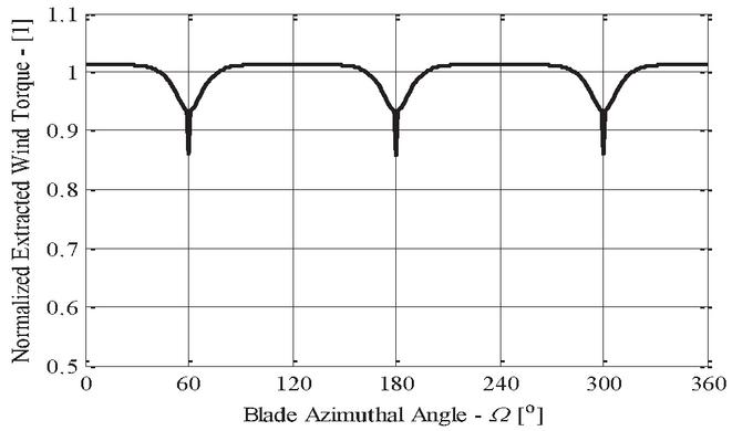
Figure 3 Normalized extracted wind torque as a function of blade azimuth angle.
Although, tower shadow effect is not the only form of excitation in wind turbines, it allows the analysis of excitation of the low natural frequency of the hydrostatic transmission as a function of wind speed and turbine rated power. This will be discussed later in this paper.
2.2 Hydrostatic Transmission Concept and Prototype
The studied hydrostatic transmission comprises a fixed displacement pump and a variable displacement motor. The rotor is connected to the pump shaft and the hydraulic motor drives the synchronous generator which is directly connected to the grid. The generator and motor are placed at ground level along with most of the hydraulic and electric/electronic components, resulting in a nacelle weight reduction, less maintenance procedures in the nacelle and reduced wear on the components due to the fluid coupling.
As mentioned previously, there are few low-speed pumps on the market and they are mostly fixed displacement units. As the focus is on the development of low-power turbines using ready-to-use components, the system is controlled by the engine. The main disadvantage of this architecture is that the pump will always provide a flow proportional to the wind speed.
Figure 4 illustrates the hydraulic circuit of the prototype where it can be seen that, as the prototype is installed in a laboratory instead of in the field, an electric motor is used to produce torque on the pump shaft instead of a real turbine. That torque is calculated by software based on a wind profile and the characteristics of a specific turbine.
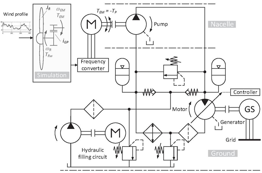
Figure 4 Prototype hydraulic circuit with the hardware in the loop architecture.
The continuous variable transmission ratio allows the variable speed operation of the rotor and constant speed operation of the generator. The generator is connected to the grid through an electric/electronic safety and synchronization system used for standard hydro-electric power generation applications. It controls the generator voltage and ensures that the generated voltage amplitude, phase, and frequency are in synch to the grid. Therefore, the generator can be connected to the grid to deliver energy to it without the need for a frequency converter. The direct connection to the grid ensures the principle of infinite busbar, where the generator speed and voltage will remain approximately constant [2]. This is true in most of cases, and especially in the prototype since the rated power of the generator is much lower compared to the power of the electric grid. The electric torque will be a consequence of the power that is supplied to the grid, allowing the rotor speed to be controlled by the motor displacement. This control method is described in Section 2.3.
The prototype operates in a hardware-in-the-loop configuration, as seen in Figure 4. The wind-rotor interaction is real-time simulated where the pump shaft torque is the output solved applying Newton’s second law for rotor and pump,
| (4) |
where, the rotor shaft mechanical efficiency, is the extracted wind torque, the pump shaft torque, is the gearbox transmission ratio, the rotor mass moment of inertia, and the rotor speed. The gearbox transmission ratio was included in the simulation because the pump in the prototype operates in higher speed compared with a real rotor speed, as it will be explained later.
The pump torque is produced by the electric motor controlled by a frequency converter. The pump speed is measured and fed back to the simulation to calculate the wind torque, establishing a power input that emulates the wind and rotor interaction.
At the output, the connection to the grid is handled by an automatic synchronizer, a voltage regulator and electric/electronic safety devices. Figure 5 shows the prototype installation layout and Table 1 its main parameters.

Figure 5 Prototype installation layout and ground equipment: a) CAD general view; b) Picture of the ground level system.
Table 1 Main parameters of the prototype
| Parameter | Symbol | Value |
| Generator rated output power | 28.5 kW | |
| Motor to pump height difference | 8 m | |
| Maximum flow rate | 110 L/min | |
| Maximum pressure difference | 210 bar | |
| Maximum electric motor speed | 1550 rpm | |
| Generator rated speed | 1800 rpm | |
| Generator output voltage | 380 V | |
| Pump volumetric displacement | 75 cm/rev | |
| Motor volumetric displacement | 60 cm/rev |
The wind turbine considered would have a rotor radius of around 6 m and a maximum power coefficient of 0.49. The estimated height of the turbine would be around 15 m, but it was downsized to meet building constraints where the prototype was installed. It was also necessary to use a smaller pump operating at a higher speed instead of a larger pump of approximately 800 cm/rev driven at low speed, as would be used in a real turbine. Consequently, the gearbox ratio to amplify the rotor speed to meet the flow rate demand and to reduce the torque was implemented in the simulation domain (Figure 4).
2.3 Hydrostatic Transmission Control
In variable speed turbines, the rotor speed is controlled by a torque that opposes the wind torque on the rotor. Using a hydrostatic transmission, the hydraulic motor operates at a constant speed locked to the grid frequency while the displacement setting control causes variation in the pump outlet pressure (motor inlet pressure) variation causing the opposite torque required by the rotor. Furthermore, the torque of the hydraulic motor will be in balance with the torque of the generator due to the electric connection to the grid.
The pump mechanical torque () is determined by
| (5) |
where and are the pump outlet and inlet pressures, respectively, is the volumetric displacement, and is the pump mechanical efficiency.
As presented in [4], the rotor torque at the maximum aerodynamic efficiency operation for a given wind speed () is derived from Equations (1) and (2) and evaluated at the ideal point, that is
| (6) |
where is the ideal power coefficient and the ideal tip speed ratio.
At equilibrium, and are equal, and the pump outlet pressure reference () can be obtained from Equations (5) and (6). Given that the prototype uses a smaller pump running at higher speed than an ideal one, the calculations include a transmission ratio between the rotor and pump, the resulting expression is
| (7) |
where, is the rotor mechanical efficiency.
At the hydraulic motor input port, the pressure () is
| (8) |
where is the hydraulic motor mechanical torque, the mechanical efficiency, the maximum volumetric displacement, the displacement setting, the outlet port pressure, and the pressure drop in the high pressure line.
Since the torque ( is a consequence of the generator connection to the grid, by controlling the displacement setting, the pump pressure is controlled, and consequently the rotor speed. Further details on the controller implemented in the prototype can be found in [29].
3 System Models
Two models of the system are used in this paper and are described in Table 2. The detailed model of the prototype is described in [27]. In this paper only the results of its validation based on the experimental data measured using the prototype are shown. A comparison is made between the detailed and the simplified model to show their agreement, which allows the conclusions from the simplified model to be extended to the detailed model and to the prototype itself.
| Model | Description |
| Detailed | Detailed model of the prototype describing the static and dynamic behaviour of all components. Validated with experimental data measured using the prototype. |
| Used to:
– obtain a detailed description of the whole system; and – evaluate static and dynamic performance. |
|
| Simplified | Model containing only the major dynamic effects of the system. Compared with the detailed model. |
| Used to:
– Determine analytically the natural frequency of the hydrostatic transmission. |
3.1 Detailed Model Description
The detailed model was implemented in LMS AMESim using standard library components. Its main features are: variable volumetric and mechanical losses of hydraulic components; compressibility, inertia, and friction in hydraulic lines; static and dynamic effects of the hydraulic charging system; static and dynamic effects of the hydraulic motor displacement control system; pressure due to the height of fluid column; static and dynamic effects of the electric motor torque delivery; static and dynamic effects of the generator connection to the grid; and simulated wind power input. Figure 6 presents an overview of the model and the validation of simulation results are shown in Section 4.1.
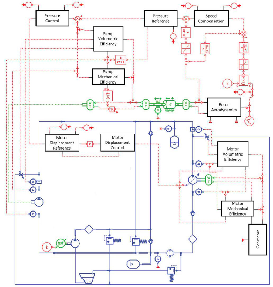
Figure 6 Overview of the detailed model.
This model is suitable to evaluate the dynamic behaviour of the system and to test different control approaches and their impact on the system performance. Although it can be used to estimate and study the natural frequency for different turbine sizes it requires re-parametrization. On the other hand, a simplified model can be used to derive the expression for natural frequency as function of main system parameters. This simplifies the estimation of natural frequency and the understanding of influencing parameters.
3.2 Simplified Model Description
The simplified model presented below allows the main dynamic effects of the system to be viewed through the rotor speed, the hydraulic pressure, and the generator speed. As it will be shown, higher frequency dynamics is not represented but the global performance is preserved. Furthermore, this model allows for determining an analytical expression for the natural frequency and other useful parameters for rapid system sizing.
Simplifications in comparison to the detailed model are: constant volumetric and mechanical efficiencies of pump and motor; no external leakage; rigid hydraulic volumes; no pressure wave propagation; and no pressure drop in the hydraulic lines. Along with that, boost system, accumulators, relief valves, etc were also not modelled in the simplified model. Figure 7 presents the system diagram and Table 3 the main variables used in the model.
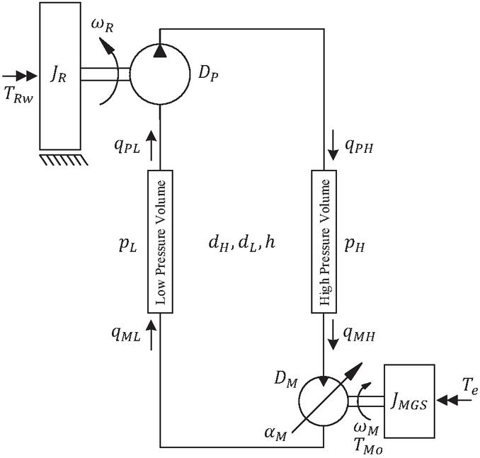
Figure 7 System diagram and variables.
| Symbol | Description |
| Hydraulic fluid effective bulk modulus | |
| Rotor speed | |
| Hydraulic motor and generator speed | |
| Hydraulic motor displacement setting | |
| Rotor mass moment of inertia | |
| Motor and generator mass moment of inertia | |
| Hydraulic motor output torque | |
| Generator electrical torque | |
| Generator electrical torque at operating point | |
| Hydraulic line length | |
| Hydraulic line diameters | |
| Motor theoretical flow rate | |
| Pump theoretical flow rate | |
| Hydraulic motor inlet and outlet flow rates | |
| Hydraulic pump outlet and inlet flow rates | |
| Hydraulic motor internal leakage | |
| Hydraulic pump internal leakage | |
| High- and low-pressure line pressures | |
| High- and low-pressure line volumes | |
| , | Pump mechanical and volumetric efficiencies |
| , | Motor mechanical and volumetric efficiencies |
Nine major dynamic equations presented below are used to model the system [27]. The continuity equations for the high- and low-pressure rigid lines, Newton’s second law equations of motion for the pump-rotor and for the motor-generator, and the electric torque from the grid are, respectively:
| (9) | |
| (10) | |
| (11) | |
| (12) | |
| (13) | |
| (14) | |
| (15) | |
| (16) | |
| (17) |
where the quantities not previously defined are listed in Table 3.
Equation (16) describes the connection of the generator to the grid, where is the change in the generator rotor torque angle due to a change in the generator speed from the synchronization speed (), which leads to a change in the electric torque (), is the synchronization torque coefficient and is the damping coefficient. Non-linearities are present in the motor torque (Equation (15)) as the product of displacement setting and pressure drop, and in Equation (12) as the product of displacement setting and motor speed. This simplified model was implemented in AMESIM using the signal library.
This model is used in the following section to obtain the analytical equation for the natural frequency. Therefore, if the model is then validated against the measurements from the prototype and the detailed model, one knows that natural frequency obtained from the model is valid for this turbine size and from there, one can estimate the natural frequency for other sizes.
3.3 Hydrostatic Transmission Natural Frequency
The hydraulic transmission natural frequency is evaluated by considering that the hydraulic ports of the high- and low-pressure lines at the motor side are closed. Therefore, the dynamics associated with the motor, generator and electric grid are excluded. This assumption does not affect the analysis, since the speed of the generator remains almost constant during operation due to the high power of the grid compared to the power of the wind turbine.
Therefore, considering that the rotor torque () is constant, and deriving Equation (13) with respect to time yields
| (18) |
Furthermore, considering that there is no flow at the motor ports and writing Equations (9) and (10) with respect to the pressure derivatives and applying them in Equation (18) leads to
| (19) |
Applying Equations (11) and (12) and the ratio of the hydraulic line volumes in Equation (19) and solving for results in
| (20) |
Consequently, the hydrostatic transmission natural frequency () is described by
| (21) |
The natural frequency is dependent on three key design parameters: pump volumetric displacement (), line volumes () and rotor mass moment of inertia (). In the following section, these three parameters are correlated to the turbine rated power to verify how the hydraulic natural frequency changes with the turbine size.
3.3.1 Correlation between turbine size and natural frequency
For a given generator output rated power (), the rotor rated power is calculated as
| (22) |
where is the pump global efficiency, is the motor global efficiency and is the generator efficiency.
Using Equation (1), the rotor swept area () needed to achieve the desired rated power is calculated using the wind rated speed () and rotor ideal power coefficient (),
| (23) |
Turbines are designed for a specific rated wind speed (). In this analysis, this design parameter is considered to be the same for all turbine sizes.
Turbine manufacturers limit the maximum blade tip linear speed () to around 65 m/s to comply with noise restrictions [3]. This limitation leads to the rotor rated angular speed (), which is calculated as
| (24) |
The steady-state rotor torque at the rated speed is calculated as
| (25) |
and the minimum required pump volumetric displacement to obtain this torque is
| (26) |
where, is the maximum pressure difference at the pump. This pressure difference should occur at rated power and is considered the same for all turbine sizes discussed hereinafter.
The line diameters are set to result in a fluid speed that produces a low pressure drop along the lines. Thus, the diameters for the high- and low-pressure lines are, respectively,
| (27) |
where and are the average fluid speed in the high- and low-pressure lines, respectively.
Consequently, the volumes in the high- and low-pressure lines can be determined, respectively, by
| (28) |
where is the tower height (assumed equal to the motor to pump height difference).
A correlation between the turbine tower height and the rotor radius for a number of turbine sizes is presented in [33],
| (29) |
The author also presented two correlations to determine the rotor mass () and the rotor mass moment of inertia (). These are, respectively,
| (30) |
and
| (31) |
Therefore, for a given range of turbines with different rated output power () the hydrostatic transmission natural frequency () can be calculated using the Equations (21) to (31).
3.3.2 Rotor excitation frequency
It is important to estimate the rotor speed at which the power transmission natural frequency is excited, in other words, when the rotor excitation frequency ( – Equation (3)) is close to the natural frequency ( – Equation (21)). In this paper, the excitation frequency is calculated for two different rotor speeds. One for the point of synchronization to the grid and one for the rotor rated speed, given by Equation (24). These two points define the operating region where the system delivers power to the grid and where resonance should be avoided.
Before synchronization, the power delivery to the grid is zero and the wind power is only sufficient to compensate the system losses. The generator is modelled as a free wheel with only viscous friction. At the synchronization point, the power input to the generator ( is
| (32) |
where is the generator viscous friction torque coefficient and is the generator rated angular speed.
The value of is calculated according to the turbine power size and it is assumed to produce a power dissipation of 1.5% of the rated output power (). The power supplied by the wind at synchronization is calculated applying in Equation (22) but without considering the generator efficiency (). Using Equations (1) and (2), the wind speed ( and the rotor speed () are calculated for the point of synchronization. Results for the comparison between natural frequencies and excitation frequencies are presented in Section 4.3.
4 Results
Section 4.1 presents the validation of the detailed model shown in Section 3.1 while the results for the validation of the simplified model described in Section 3.2 can be found in Section 4.2. An analysis of the range of frequencies of a wind turbine with nacelle-to-ground hydrostatic transmission discussed in Section 3.3 is presented in Section 4.3.
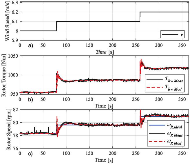
Figure 8 Detailed model validation – Transmission input: a) Wind Speed; b) Rotor Torque; c) Rotor Speed.
4.1 Validation of the Detailed Model
For the validation of the detailed model (Figure 6), simulation results are compared with measured data from the prototype shown in Figure 5. Figure 8 presents results for the rotor torque and speed for step inputs of the wind velocity speed. In Figure 8b a good agreement between the measured and simulated input torque, for dynamic and static behaviour, can be observed. Figure 8c shows that the system is controlled and kept at its ideal point (. At the same time, the dynamic behaviour of the model is similar to the experimental results, which is an indication of the model’s capacity to describe the real system.
Figure 9 presents the validation of the model for the rotor aerodynamic performance through the tip speed ratio () and the power coefficient (). Since these two parameters are functions of the turbine speed, the model and experimental results are also expected to show good agreement. This figure also shows the efficacy of the implemented controller in controlling the rotor near to its maximum aerodynamic performance.
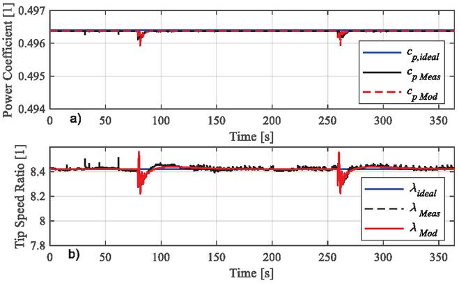
Figure 9 Detailed model validation – rotor performance: a) power coefficient and b) tip speed ratio.
Figure 10 shows the behaviour of the high-pressure line, including the reference value calculated by the controller (see Figure 6) and the effective pressure at the hydraulic line. Despite a small difference in pressure at steady state conditions, the general dynamic and static behaviour are well described by the model. The controller implemented in the simulation model is replicated in the prototype. There is a maximum error of around 2% on calculating the pressure reference by simulation and experimentally. The similarity in dynamic response shown in this and the figures above demonstrates the ability of the model to describe dynamic effects.
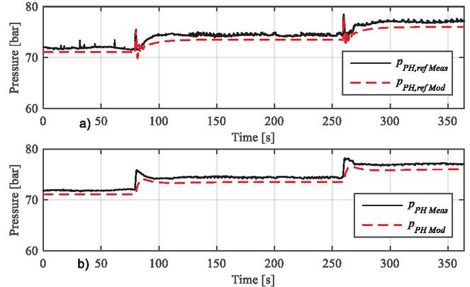
Figure 10 Detailed model validation – high pressure line: a) reference pressure and b) pump outlet pressure.
As mentioned before, the generator is connected to the grid, such that the prototype reproduces a real operating condition. Figure 11 presents experimental and simulation results for the electric frequency of the grid. The generator operates with nearly constant frequency, indicating that the principle of infinite busbar included in the model is an acceptable assumption. As defined by the Brazilian Electricity Regulatory Agency [34], for steady state and normal conditions the frequency variation should be lower than 0.1 Hz. After periods of disturbance, it should return to the range of 0.5 Hz within 30 s. As shown in Figure 11, the maximum error achieved with the prototype and by simulation is below 0.5 Hz of the nominal value during disturbances. This demonstrates that the prototype meets current regulations.
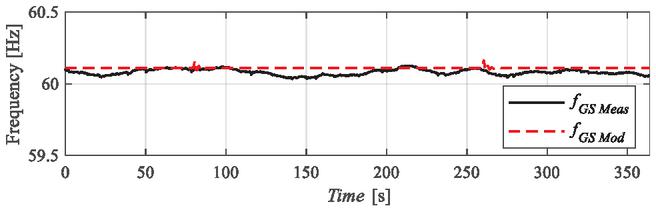
Figure 11 Model validation – generator frequency.
Based on the results discussed above along with additional data reported in [27], it can be observed that the detailed model describes very well the hydrostatic transmission and the coupling of the generator to the grid. This model can therefore be used as a reference for the development and analysis of a simplified model that may not achieve such good agreement with the measured data but would allow complementary studies, such as the determination of the natural frequency, to be carried out.
Simulation responses of the wind turbine using a realistic wind profile are shown in Figure 12. As it can be seen, despite the high varying wind profile, the system is able to track the reference pressure profile (Equation (7)), which results in the tracking of the ideal rotor speed. Once the rotor speed is close to the reference value, the tip speed ratio will be close to the ideal value too (Equation (2)).
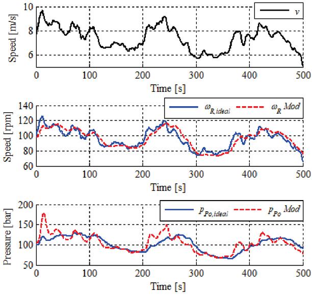
Figure 12 Wind turbine simulation – real wind speed. a) Wind speed; b) Rotor speed; c) Pump outlet pressure.
The experimental results presented in this section demonstrate the capacity of the system to deliver power directly to the grid without the use of frequency converters and all of this is accomplished with off-the-shelf components. Although it is not the focus of this paper, the control strategy also proved to be sufficiently effective in controlling the system to achieve maximum aerodynamic efficiency [27].
4.2 Results From the Simplified Model
This section presents results that show the agreement between the simplified model (Section 3.2) and the detailed model (Section 3.1). The comparison is made for the rotor speed, the pressure difference between lines, the controller reference pressure, and the generator speed. Since the main objective is to evaluate the dynamic effects, results were normalized to their initial value. Figure 13 presents simulation results for different wind speed step inputs.
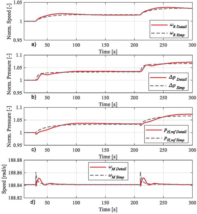
Figure 13 Simplified model evaluation; a) rotor speed; b) pressure difference; c) reference pressure; d) generator speed.
Although the simplified model has a reduced order compared to the detailed model and uses constant instead of time-varying parameters, such as the efficiencies, it is able to describe the transient and steady-state behaviour satisfactorily. Therefore, the second-order model can be used to calculate the natural frequency of the transmission and it can be extended to the actual wind turbine.
4.3 Analysis of Hydrostatic Transmission Natural Frequency
The analysis described in this section uses Equation (21) to calculate the natural frequency, with the turbine characteristics determined according to Sections 3.3.1 and 3.3.2. The parameters used for the calculations are shown in Table 4. The range of turbine sizes evaluated is up to 600 kW ().
Table 4 Parameters used for the natural frequency analysis
| Parameter | Value |
| 1.5 m/s | |
| 6 m/s | |
| 0.95 | |
| 0.95 | |
| 20 MPa | |
| 65 m/s | |
| 1.50 GPa | |
| 12 m/s | |
| 0.49 | |
| 8.42 | |
| 188.49 rad/s | |
| 1.225 kg/m |
As expressed by Equation (3), the excitation frequency caused by the tower shadow effect is dependent on the rotor angular speed. At the synchronization of the generator with the grid, is calculated according to Section 3.3.2 while at the rated rotor speed is determined by Equation (24). Figure 14 presents these two excitation frequencies along with the hydrostatic transmission natural frequency () calculated by Equation (21) for a range of turbine output rated power values ().
The dashed vertical line is the rated power of the studied prototype. The hydraulic system natural frequency () is below the maximum rotor excitation frequency, which occurs at the rated rotor speed. It is also below the excitation frequency at synchronization. At a certain point the rotor speed will operate with the system natural frequency, but this occurs while the rotor is gaining speed to achieve the synchronization point (operating region in Figure 2). In this region there is no output power, so the issues related to resonance should not be very significant because they would be partially damped by the system losses and not transmitted to the generator. As the turbine rated output power increases the natural frequency becomes closer to the rotor excitation frequency and this could lead to resonance issues closer to the point of synchronization, which might be critical.
Moreover, considering hydrostatic transmissions comprised of off-the-shelf components and with a single pump, the nominal power is estimated to be limited to around 500 kW [7]. For higher powers it is necessary to use a group of pumps in parallel and the same applies to the motor. This limitation would not only apply to the pump and motor but also to the other components required, such as heat exchangers and filters. Their maximum flow rate as individual components would be a limiting factor, which would also result in a need for large pipe diameters. For higher nominal power, the height of the turbine is also a constraint for the installation of pipes from the nacelle to the bottom of the tower.
Another important topic that was not addressed until this point is the dynamic response of the hydraulic motor displacement setting control. It must be fast enough to be able to react to certain types of faults that might occur in the system. However, it is not assessed in this paper since the focus was on tower shadow effect, and because it is essentially not present during operation of the prototype, as estimated in the calculation. At the same time, no issues of resonance were observed during the experiments.
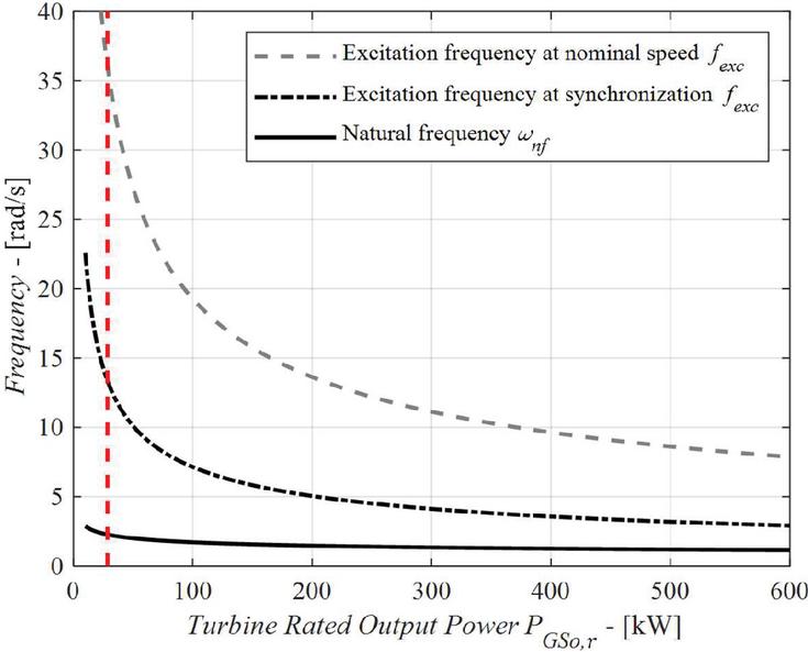
Figure 14 System natural frequency and excitation frequencies.
5 Conclusions
In this paper a prototype of a nacelle-to-ground hydrostatic transmission demonstrated the concept feasibility. It is composed of a hydrostatic transmission and a synchronous generator with direct connection to the grid. The prototype was built and the experimental data obtained demonstrated the capacity of the system to deliver power to the grid without the use of frequency converters and only using off-the-shelf components.
To support the analysis and development of such systems two simulation models were derived and their validation was presented. A detailed non-linear model was used to replicate most of the dynamic and static characteristics observed with the test bench, allowing the assessment of the system performance and development of controllers. A simplified model was used to determine the natural frequency of the system.
The detailed model was validated against experimental data measured using the prototype. In future studies, this model could be used to evaluate the system behaviour under other scenarios that are not possible to test with the prototype, as well as to support the design of systems of other rated powers. The simplified model showed a good agreement with the detailed model, which allows the conclusions gained from it to be extended to the prototype itself.
As discussed herein, a nacelle-to-ground hydrostatic transmission concept faces constraints for higher rated powers at the same time indicating a more feasible application to lower rated powers. These constraints are related to the resonance, the availability of off-the-shelf components and in some cases the need to use components in parallel. The height between nacelle and ground level components can also introduce excessive load-loss and pressure surges due to pressure wave propagation; however, this issue was not taken into account in this paper.
In terms of the concept, it was shown that the system should not have resonance issues at the hydrostatic transmission natural frequency up to a turbine size of 600 kW and above this size resonance issues may be encountered during synchronization. The experiments performed in this paper serve as a proof of concept for low rated power applications. Further studies are required to evaluate the feasibility of the solution when applied to an actual turbine. For example, the actual mass saving, the actual reduction in maintenance procedures at the top of the nacelle, the applicability of off-the-shelve components for rated powers up to 600 kW, the development of the swivel union between tower and nacelle and capability of the system and controller to react to load rejection when there is a shutdown of the grid.
Acknowledgements
We gratefully acknowledge the support from Reivax S/A Automation, Control, Parker Hannifin Ltd., and CNPq (National Council for Scientific and Technological Development).
References
[1] Hau, E. Wind Turbines – Fundamentals, Technologies, Application, Economics. 2nd Edition. Springer-Verlag. Germany. 2006.
[2] Shepherd, W., Zhang, Li. Electricity Generation Using Wind Power. World Scientific Publishing Co. Pte. Ltd. Singapore, 2011.
[3] Burton, T., Jenkins, N., Sharpe, D., Bossanyi, E. Wind Energy Handbook. 2nd Ed. John Wiley and Sons, Ltd. Chichester, UK. 2011.
[4] Wang, F,. Trietch, B., Stelson, K. A. Mid-sized wind turbine with hydrostatic-mechanical transmission demonstrates improvement energy production. Proc. 8th International Conference on Fluid Power Transmission and Control (ICFP 2013), Hangzhou, China, 2013.
[5] Ribrant, J., Bertling, L. M. Survey of Failures in Wind Power Systems with Focus on Swedish Wind Power Plants curing 1997-2005. IEEE Transactions on Energy Conversion, Vol. 22, No. 1, 2007. DOI: \nolinkurl10.1109/TEC.2006.889614.
[6] Diepeveen, N., Laguna, A. J. Preliminary Design of the Hydraulic Drive Train for a 500kW Prototype Offshore Wind Turbine. Proceedings of the 9th International Fluid Power Conference, Volume 3. IFK2014. Aachen, Germany. 2014.
[7] Baldo, G. Design and Comparative Analysis of Hydraulic Solutions for Control of Power, Yaw and Pitch in Wind Turbine (in Portuguese). Master’s Thesis. Mechanical Engineering Department. Federal University of Santa Catarina. 2019.
[8] Bosch Rexroth. Drive Systems Hägglunds: Catalog: BR386-1BR. 2011. 32 p. Atibaia, Brasil, 2011.
[9] Schmitz, J., Vatheuer, N., Murrenhoff, H. Development of a Hydrostatic Transmission for Wind Turbines, 7th International Fluid Power Conference, Aachen, Germany, 2010.
[10] Wang, F., Chen, J., Xu, B., Stelson, K. A. Improving the reliability and energy production of large wind turbine with a digital hydrostatic drivetrain. Applied Energy, Vol. 251, 2019. DOI: \nolinkurl10.1016/j.apenergy.2019.113309.
[11] Rampen, W., Dumnov, D., Taylor, J., Dodson, H., Hutcheson, J., Caldwell, N. A digital Displacement Hydrostatic Wind-turbine Transmission. International Journal of Fluid Power, Vol. 22 1, 87–112, 2021. DOI: \nolinkurl10.13052/ijfp1439-9776.2213.
[12] Sasaki, M., Yuge, A., Hayashi, T., Nishino, H., Uchida, M., Noguchi, T. Large Capacity Hydrostatic Transmission with Variable Displacement. The 9th International Fluid Power Conference, 9, IFK. Aachen, Germany. 2014.
[13] Varpe, S. A. Control system on a wind turbine. Master’s Thesis. Department of Energy and Process Engineering, Norwegian University of Science and Technology. Trondheim, Norway. 2008.
[14] Dolan, B., Aschemann, H. Control of a Wind Turbine with a Hydrostatic Transmission – an Extended Linearisation Approach. 17th International Conference on Methods and Models in Automation and Robotics. Poland, 2012.
[15] Diepeveen, N. F. B., Laguna, A. J. Dynamic Modelling of Fluid Power Transmissions for Wind Turbines. Proceedings of the EWEA Offshore 2011 Conference, Amsterdam, The Netherlands, 29 November-1 December. 2011.
[16] Ai, C., Bai, W., Zhang, T., Kong, X. Research on the key problems of MPPT strategy on active power control of hydraulic wind turbines. J. Renewable Sustainable Energy 11, 013301, 2019. DOI: \nolinkurl10.1063/1.5029313.
[17] Yujiong, G., Bingbing, W., Weipeng, Y., Dian, X. Research an analysis of experimental approach to study the transmission characteristics of full hydraulic wind turbine generation technology, J. Renewable Sustainable Energy, Vol. 7, 043118, 2015. DOI: \nolinkurl10.1063/1.4922355.
[18] Lin, Y., Tu, L., Liu, H., Li, Wei. Hybrid Power Transmission Technology in a Wind Turbine Generation System. IEEE/ASME Transactions on Mechatronics. 2014.
[19] Mohanty, B., Stelson, K. A. Experimental Validation of a Hydrostatic Transmission for Community Wind Turbines. Energies, Vol. 15, 376, 2022. DOI: \nolinkurl10.3390/en15010376.
[20] Laguna, A. J., Diepeveen, N. F. B., Van Wingerden, J. W. Analysis of Dynamics of Fluid Power Drive-trains for Variable Speed Wind Turbines: a Parameter Study, IET Renewable Power Generation, Vol. 8, Issue: 4, pp. 398-410, May 2014.
[21] Diepeveen, N., Mulders, S., Tempel, J., Field tests of the DOT500 prototype hydraulic turbine. 11th International Fluid Power Conference, Aachen, Germany, 2018.
[22] Qin, C., Innes-Wimsatt, E., Loth, E. Hydraulic-electric hybrid wind turbine: tower mass saving and energy storage capacity, Renewable Energy, Vol. 99, pp. 69–79, 2016. DOI: \nolinkurl10.1016/j.renene.2016.06.037.
[23] Roggenburg, M., et al. Techno-economic analysis of a hydraulic transmission for floating wind turbines. Renewable Energy, Vol. 153, pp. 1194–1204, 2020. DOI: \nolinkurl10.1016/j.renene.2020.02.060.
[24] Liu, Z., Yang, G., Wei, L., Yue, D., Variable speed and constant frequency control of hydraulic wind turbine with energy storage system. Advances in Mechanical Engineering, Vol. 9(8) pp. 1–10, 2017. DOI: \nolinkurl10.1177/1687814017715195.
[25] Flesch, E. A. Design of a Hydrostatic Transmission for Horizontal Axis Wind Turbines (in Portuguese). Master’s Thesis. Mechanical Engineering Department, Federal University of Santa Catarina. Florianópolis, Brazil, 2012.
[26] Rapp, J., Turesson, J. Hydrostatic Transmission in Wind Turbines: Development of Test Platform. Master’s Thesis. Department of Management and Engineering. Linkoping University. 2015.
[27] Raduenz, H. Experimental and theoretical analysis of a hydrostatic transmission for wind turbines. Master’s Thesis. Mechanical Engineering Department. Federal University of Santa Catarina. 2018.
[28] Flesch, E. A., Raduenz, H., De Negri, V. J. Analysis of a hydrostatic transmission system for horizontal axis wind turbines. In: 14th Scandinavian International Conference on Fluid Power. Proceedings of the 14th Scandinavian International Conference on Fluid Power. Tampere, Finland. 2015.
[29] Raduenz, H., De Negri, V. J. Speed Compensation in Hydraulic Wind Turbine Control. In: 2018 IEEE Global Fluid Power Society PhD Symposium, 2018, Samara, Russia. Proceedings of the 2018 IEEE Global Fluid Power Society PhD Symposium, 2018.
[30] Chen, W., Wang, X., Zhang, F., Liu, H., Lin, Y., Review of the application of hydraulic technology in wind turbine, Wind Energy, Vol. 23(7), pp. 1495–1522, 2020. DOI: \nolinkurl10.1002/we.2506.
[31] Dolan, D. S. L., Lehn, P. W. Simulation Model of Wind Turbine 3p Torque Oscillations due to Wind Shear and Tower Shadow. IEEE Transactions on Energy Conversion, Vol. 21, No. 3, September 2006.
[32] Vatheuer, N., Schmitz, J., Murrenhoff, H. Efficient Hydrostatic Heavy-Duty Drive Train in Renewable Energy Branch, Proceedings of the Twelfth Scandinavian International Conference on Fluid Power: SICFP11, Tampere, Finland, May 2011.
[33] Hassan, G. Wind Energy – The Facts. 2009. \nolinkurlhttps:/www.wind-energy-the-facts.org/hub-height.html. Accessed on: 16th January 2018.
[34] Aneel – Brazilian Electricity Regulatory Agency. Procedimentos de Distribuição de Energia Elétrica no Sistema Elétrico Nacional – PRODIST, Módulo 8 – Qualidade da Energia Elétrica, (in Portuguese). https:/www.aneel.gov.br/modulo-8 (Accessed on September 2021).
Biographies

Henrique Raduenz received his master’s degree in Mechanical Engineering at the Federal University of Santa Catarina (UFSC), Brazil, in 2018. He received his doctor degree in Mechanical Engineering at UFSC and at Linköping University (LiU), Sweden, in 2022. He is currently working as hydraulic systems development engineer at Volvo Construction Equipment, Sweden. His topic of research is fluid power systems for mobile machines.

Gabriel Linhares Baldo received the Mechanical Eng. degree in 2017, from UNISINOS, Brazil, and master’s degree in Mechanical Engineering at the Federal University of Santa Catarina (UFSC), Brazil, in 2019. Currently works at the company Bosch Rexroth developing hydraulic command blocks applied to agricultural machines and implements in Pomerode, Brazil.

Victor Juliano De Negri received the Mechanical Eng. degree in 1983, from UNISINOS, Brazil, M. Eng. degree in 1987 and D. Eng. degree in 1996, both from UFSC, Brazil. He is professor at the Department of Mechanical Engineering at the Federal University of Santa Catarina (UFSC) and the head of the Laboratory of Hydraulic and Pneumatic Systems (LASHIP). He is member of ASME, ABCM, and of the Board of Directors of GFPS and Associate Editor of the International Journal of Fluid Power. His research areas include analysis and design of hydraulic and pneumatic systems and components and design methodologies for mechatronic systems.
International Journal of Fluid Power, Vol. 25_1, 89–126.
doi: 10.13052/ijfp1439-9776.2514
© 2024 River Publishers