Comprehensive Application-Based Analysis of Energy-Saving Measures in Pneumatics
Vladimir Boyko1,*, Fedor Nazarov1, Wolfgang Gauchel2, Rüdiger Neumann2, Matthias Doll2 and Jürgen Weber1
1Chair of Fluid-Mechatronic Systems (Fluidtronics) – TUD Dresden University of Technology, Helmholtzstraße 7a, 01069 Dresden, Germany
2Festo SE & Co. KG, Ruiter Straße 82, 73734 Esslingen, Germany
E-mail: vladimir.boyko@tu-dresden.de; fedor.nazarov@tu-dresden.de
*Corresponding Author
Received 18 October 2023; Accepted 02 April 2024;
Abstract
The current economic and ecological situation emphasizes the importance of energy efficiency for the industry. Widely applied pneumatic systems are particularly affected by this issue because of their comparatively high energy consumption. To increase the efficiency of pneumatics, numerous energy-saving components and circuits have been developed over the last decades. However, the applicability of these measures for different load cases, their impact on the drive performance, and real economic benefit often remain unclear for the end-user. In this paper, the applicability of the energy-saving measures for typical load cases was analysed on example of two pneumatic cylinders (32 and 50 mm bore) based on their technical performance, energy consumption, and costs. The evidence brought by this experimentally verified research can help one to make a correct decision about configuration of a new pneumatic drive or retrofitting an existing system regarding the costs, efficiency, and application specifics. All studied energy-saving measures were compared to a well-sized meter-out controlled reference drive. It is shown that considerable energy savings without performance loss of a well-sized cylinder are achievable only by means of sophisticated cylinder control. In contrast, simple non-electronic components are mostly convenient only for the retrofitting of an oversized cylinder.
Keywords: Energy efficiency, pneumatics, compressed air systems, dimensioning, sizing, energy-saving circuit.
1 Introduction
Pneumatics is one of the most essential drive technologies in modern automation systems. Due to its numerous advantages such as simplicity, robustness, reliability, high energy density and low investment costs, pneumatics is used for a wide range of applications including handling technology, assembly automation, packaging and food industry, printing, textile machines etc.
In most industrialised countries, the industry sector represents a significant portion of electrical energy consumption (e.g. 44% of total electricity consumption in Germany in 2021 [1]). The compressed air supply contributes approximately 10% (80 TWh/a) to industrial energy consumption in the European Union, as measured in 2001 by Radgen & Blaustein [2]. Although no recent studies have been conducted, more recent findings [3–5] estimate that compressed air supply accounts for around 7% of industrially required electrical energy in Germany, equivalent to 16 TWh/a.
Reducing industrial energy consumption is therefore an important step towards achieving climate protection goals [6]. Especially pneumatics is confronted with this issue, as it often shows higher energy consumption in comparison to electromechanics. According to [3–5, 7–9], there is still a significant saving potential up to 40% (i.e. 6.4 TWh/a for Germany) for all compressed air consumers. Pneumatic drives hold a significant share of this potential.
In recent years, various energy-saving solutions for pneumatic cylinder drives have been developed to realise these savings. The most crucial measure is correct actuator sizing, since oversized actuators cause unnecessarily high energy consumption. However, determining the correct cylinder size depends on application-specific criteria such as inertial mass, force profiles, and transition times, which may not always be readily available. As a result, industrial users often rely on empirical data when sizing cylinders.
Apart from the correct sizing, the energy consumption can be reduced through energy-saving circuits (ESCs). Since the applicability of the ESCs depends on the specific application and load, it still remains unclear, what saving potential is feasible with the ESCs. For some of the ESCs, exaggerated energy savings can be found in the literature, resulting from using heavily oversized cylinder drives to estimate reference air consumption, which is then compared to air consumption of the same cylinder with the studied ESC. In these cases, correct cylinder sizing could have prevented the increased energy consumption without the need for ESCs. Another common issue is neglecting the end cushioning process, essential for a smooth and reliable cylinder operation and short transition times. Decision-making should also consider additional costs and the impact of ESCs on cylinder performance (hereinafter measured by transition times).
Having said that, so far there is no objective study on the ESCs implemented and tested with industrially relevant load cases and fairly compared with a well-sized reference. Such a comparison would bring transparency into the ESC-market, support users in selecting the right cylinder and the ESC for a specific load case, and reduce the compressed air consumption and subsequent energy costs. Hence, the present article aims to evaluate the applicability and to quantify the real energy savings of various ESCs for eight typical pneumatic applications (load cases). These load cases were specified by inertial mass, transition times, and force profiles for each of the cylinders studied (Ø32200 and Ø50200). Transition times for retraction and extension strokes served as performance indicators for the cylinder, compared to the fastest possible transition times of a well-sized reference. To evaluate the quality of the end cushioning process, the kinetic energy of the moving mass before impacting the cylinder end cup was compared to the allowed maximum for pneumatic cylinders.
The term “energy efficiency” used in this article corresponds to the description given in the EU Energy Efficiency Directive 2023/1791/EU and is defined as the ratio of useful energy output to the total energy input in a system. In this terminology, an energy-efficient solution is one that features the minimum necessary energy consumption, which, in turn, is defined here as the pneumatic air volume required to perform a given task.
2 State of the Art
A detailed overview of the state of the art in the field of energy-efficient pneumatics was last given in [10–14]. Meanwhile, publications and products of more recent date have also become known, which are presented below according to the structure proposed in [13] (see Figure 1).
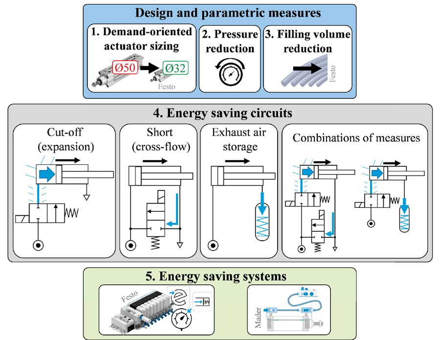
Figure 1 Classification of energy-saving measures.
2.1 Demand-Oriented Actuator Sizing
To reduce the energy consumption by counteracting an oversizing of pneumatic drives such as cylinders, various dimensioning methods based on different physical assumptions have been developed. In [15], Doll et al. proposed a method for pneumatic cylinder dimensioning by means of the Pneumatic Frequency Ratio (PFR ). Rakova & Weber considered in [16] a sizing method based on the exergy equilibrium of the cylinder. Vigolo & De Negri developed an approach for the determination of an optimal cylinder diameter with the aid of the operating point analysis [17]. Boyko et al. [18] compared the dimensioning methods elaborated in [15] and [16] with the force equilibrium method. The supplementation of the force equilibrium method by TCO criteria and its application on an industrial assembly system is described in [19].
Additionally, various sizing tools of pneumatics manufacturers are freely available, e.g. Pneumatic Sizing by Festo SE & Co. KG based on [15]. Simulation software such as SimulationX [20] or DSHplus [21] can be also used for the cylinder sizing.
2.2 Pressure Reduction
The concept of two different pressure levels for the extension and retraction of a pneumatic actuator was introduced by Fleischer [22]. An example of a pressure reducing product solution for the return stroke of the cylinder is the ASQ flow valve by SMC Corporation [23], whose application was experimentally evaluated in [24] and [25]. The Motion App “ECO drive” of the Festo Motion Terminal VTEM [26] also allows a flexible pressure adjustment. By using two different pressure levels within a pneumatic system, significant savings were demonstrated in [19] and [27]. In the paper [28], a novel pressure control is presented in which the operating pressure of a pneumatic system is automatically set depending on the mass of the workpiece.
The idea of a combined downstream and adaptive upstream throttling, demonstrated in [29, 30], can also be assigned to this category, as its savings effect results from the reduced operating pressure.
2.3 Filling Volume Reduction
Many technical solutions are now available on the market that make it possible to significantly reduce the filling volume between a directional control valve and a pneumatic cylinder, and thus the compressed air consumption. For example, by systematically using compact valve-cylinder combinations (e.g. IVAC units [31], CVQ [32] or DNC-V cylinders [33]) or microvalves [34], one can achieve considerable energy savings.
2.4 Energy-Saving Circuits
This category can be subdivided as follows:
Cut-off (expansion) circuits. The possibility of saving energy by closing the compressed air supply during the cylinder movement, thus allowing the compressed air supplied to the cylinder chamber to expand and to drive the piston, described by Otis [35], has led to the development of a pneumatic bridge circuit with independent metering valve control, which is patented e.g. in [36, 37], now broadly used in the Festo Motion Terminal and further investigated (see e.g. [38–50]). Furthermore, there have been investigations on PWM control of the cut-off circuit [51, 52] and its applicability for a vertically mounted cylinder [53, 54]. Since the saving effect of this circuit depends strongly on the initial cylinder size and the valve control parametrisation, no definite savings can be stated for this circuit type. In the sources listed above, energy savings up to 80% are claimed (mostly for oversized cylinders).
Short (cross-flow) circuits. With this circuit type, the cylinder chambers are connected to each other during the extension movement, so that the air flowing out of the rod chamber can be supplied to the piston chamber, thus reducing the energy consumption up to 40%. Various realisations of the short circuit were patented in [55–60] and investigated in e.g. [42, 61], especially for servopneumatics [62–67]. This circuit type has also been developed by SMC Corporation as a retrofit solution Air Saving Box [68].
Exhaust air storage circuits. This circuit allows to reuse the exhaust air out of the rod chamber for the return stroke of the cylinder, which is comparable with the piston moving against a gas spring. Such a principle was patented in e.g. [69–71]. Shi et al. conducted a measurement-assisted research on exhausted air reclaiming devices [72]. Novaković et al. analysed the influence of exhausted air saving on the actuator dynamics [73]. In [74], a configuration and working principles for the exhaust air recovery from both cylinder chambers were introduced. Using the new circuit, the experimental results showed the energy recovery efficiency above 23%. In their work [75], Šešlija et al. developed and studied a control scheme for the reclaiming of exhausted air in a multi-actuator pneumatic system, achieving energy savings up to 37%. A cylinder with the exhaust air recovery circuit directly integrated into the cylinder housing was patented by SMC Corporation [76–78] and is now purchasable as Air Saving Cylinder [79].
Combinations of energy-saving circuits. It is also possible to combine different saving principles within one circuit to achieve even greater energy efficiency improvement. For example, in the control concept introduced by Krytikov et al. [80, 81], the simultaneous use of the exhaust air and two different pressure levels for position-dependent acceleration and deceleration of a pneumatic cylinder is described, demonstrating high energy efficiency without performance loss. In [82], the energy and cost efficiency of various combinations of energy-saving measures are evaluated on example of typical drive tasks.
2.5 Energy Saving Systems
This category includes systems solutions (mostly digitised) that offer increased application flexibility combined with the energy efficiency. The Festo Motion Terminal VTEM [83] combines various motion and monitoring tasks in a single intelligent valve unit. Depending on the application, different energy-saving circuits can be implemented via Motion Apps of the VTEM. A self-adjustable control system for pneumatic cylinders, PCC Blue, was brought onto the market by Mader GmbH and can be used for setting the minimum possible travel time with minimum energy consumption [84].
2.6 Further Solutions
In addition to the energy-saving measures at the actuator level described above, numerous solutions exist to address energy losses during the generation and transmission of compressed air, which are not further considered in this article. These include a demand-based compressor design with heat recovery, the usage of compressors and dryers with electronic control, optimal sizing of piping for the distribution system, as well as the implementation of leakage detections systems. The potentially achievable energy savings are highly application-specific and amount to 10–20% on average and even higher if applying heat recovery systems [4, 7–9, 14].
3 Selected Energy-Saving Solutions
From the saving measures described in Chapter 2, the following solutions were chosen for further study and comparison with the standard circuit with meter-out throttling (Figure 2, a)) based on a preliminary assessment of their usability, practicability and theoretical savings potential. Both purely pneumatic-mechanical as well as pneumatic-electrical control solutions were selected and examined.
3.1 Design and Parametric Measures
Standard Meter-Out Circuit. As a reference, a standard meter-out controlled circuit with a well-sized cylinder is used (Figure 2, a)).
Pressure Regulator. A conventional pressure regulator (e.g. Festo VRPA [85], SMC AS-R [86]) can be installed directly inline between the consumer and the directional valve, reducing the pressure if the full network pressure is not required, mostly for non-working return strokes (s. Figure 2, b)). In case of an oversized cylinder, a second pressure regulator (highlighted grey in Figure 2, b)) can be applied also for the extension movement.
Single-Acting Cylinder. In this cylinder type, the retraction movement occurs by means of a mechanical spring without compressed air supply being necessary (Figure 2, c)). However, the spring stiffness reduces the achievable pressing force of the cylinder during extension. Besides, the single-acting cylinders usually come without an integrated pneumatic end cushioning. This decreases the maximum load mass and speed because of the lower kinetic energy acceptable in the end of the stroke.
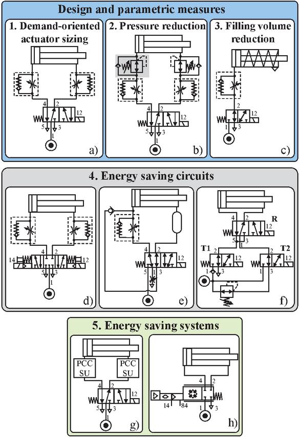
Figure 2 Standard meter-out circuit (a) and energy-saving solutions selected for the study: (b) pressure regulator; (c) single-acting cylinder; (d) supply air cut-off; (e) short circuit; (f) 3-phase movement circuit; (g) PCC Blue; (h) Festo Motion Terminal VTEM.
3.2 Energy Saving Circuits
Supply Air Cut-Off. In this circuit, the supply air is cut off by switching a 5/3 directional valve to its middle position when the cylinder piston reaches the end position, as investigated e.g. in [38] (Figure 2, d)).
Short Circuit. The main feature of the circuit shown in Figure 2, e) is the reuse of the air from piston chamber, so than no compressed air supply is needed for the retraction movement (e.g. see [76–79]).
3-Phase Movement Circuit. The circuit presented by Krytikov et al. in [80, 81] consists of three solenoid valves: a 5/2 valve (R) to change the cylinder movement direction, a 3/2 valve (T1) to redirect the exhaust air flow either to atmosphere or back to the supply line, as well as another 3/2 valve (T2) for switching the pressure level between the full and reduced pressure (Figure 2, f)). By corresponding activation of the valves depending on the actual piston position, three difference movement phases can be achieved:
1. Acceleration: Initial movement with high pressure against the atmosphere,
2. Braking: Further movement with lower pressure, the exhaust air is fed to the supply line,
3. Fixation: Final movement with lower pressure, the exhaust line is connected to the atmosphere.
3.3 Energy Saving Systems
PCC Blue. PCC Blue is a self-learning module for reducing the energy consumption of cylinders. Using a central control unit and two sensor units per cylinder, the minimum required pressure can be identified and set (Figure 2, g)). PCC Blue system is currently only operational for cylinder size Ø50 upwards.
Festo Motion Terminal (VTEM). VTEM is a mechatronic module comprising several valve slices, each slice consisting of four 2/2 proportional valves connected to form a full bridge (Figure 2, h)). The configuration of the full bridge can be defined by applying various pre-programmed Motion Apps. Thus, different valve types (e.g. 4/3, 5/2) and functions (pressure reduction, soft stop etc.) can be specified for each valve slice without altering the mechanical connection. In the current work, the Motion App “ECO drive” was used for all load cases of Table 4 with the exception of the vertical load cases 2-1 and 2-2, for which the Motion App “Supply and exhaust air flow control” was deployed. “ECO drive” allows to operate the cylinder with the minimum pressure necessary for the load [26], whereas the air flow control app serves to quickly build up pressure especially required for vertical tasks.
4 Definition of Load Cases and Applicability of the Energy-Saving Circuits
The energy savings of ESCs and their impact on the cylinder performance rely heavily on a particular load case. For example, an ESC utilizing expansion energy (s. Section 2.5) may perform greatly with high-dynamic horizontal tasks, whereas naturally cannot provide any savings if full pressure force is needed at the end of the stroke (e.g. when heaving and holding a mass). This difference in feasible savings is brought about by the cylinder pressure in the end positions ( for extension and for retraction stroke) that impacts the amount of consumed and exhausted air. For a cylinder with a stroke l, piston and shaft diameters D and d respectively, dead volume and tube volume between the valve and the cylinder , the air consumption referred to the normal conditions according to ISO 6358 is composed of:
| (1) |
Besides reducing the air consumption, ESCs can influence the transition times and of extension and retraction strokes respectively. Generally, the transition times of a pneumatic drive with an ESC should not exceed those of a reference drive with meter-out throttling to avoid slowing down the production line and questioning the benefits of ESCs. Additionally, the impact of ESCs on the damping capacity of pneumatic end cushioning, commonly integrated into the end caps of cylinders, can limit their applicability. Summing up, when applying an ESC, three criteria should be considered: load-specific energy savings, performance (transition times), and residual kinetic energy of the moved mass after passing the pneumatic end cushioning.
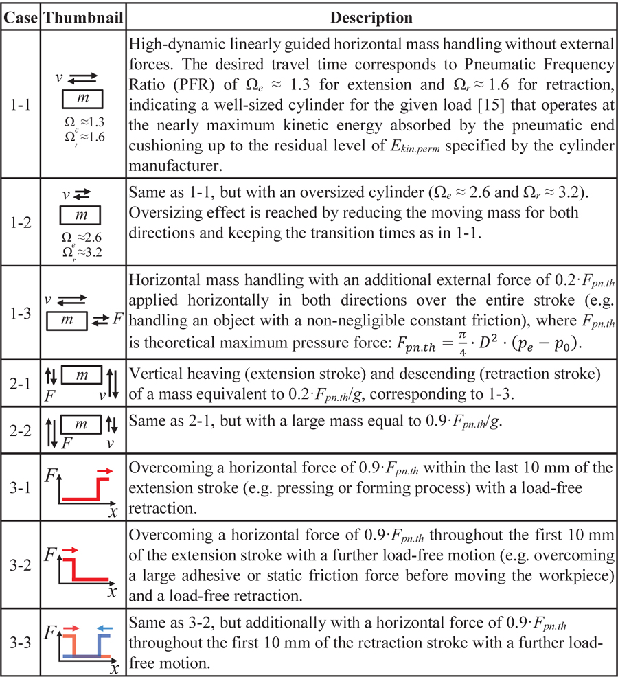
In this study, the variety of pneumatic applications was reduced to eight prevailing load cases (s. Table 1) that demonstrate different combinations of force and inertial loads and are also differently challenging for the pneumatic end cushioning. The selection of these cases was based on their occurrence in the relevant literature [87–89] and industry feedback.
In the following, the behaviour of two ISO 15552 pneumatic cylinders Ø32200 and Ø50200 as well as of two ISO 6432 single-acting cylinders Ø3250 and Ø5050 (since no such cylinders are available with a stroke of 200 mm) was studied with these combinations of the ESCs and load cases. The study was carried out at supply pressure bar. The exact parameters for the reference drive with meter-out throttling, estimated by the method described in Chapter 5, are summarized in Table 2. To compare saving potential and performance of the ESCs with the reference, both simulative and experimental studies were carried out, as described in Chapters 5 and 6.
Table 1 Load cases selected for the study
5 Simulation and Parameterisation
As already mentioned, both air savings and drive performance depend on the cylinder size. Using a heavily oversized cylinder as a reference for comparison with an ESC can mislead and favour the ESC in terms of air saving potential. Faulty or unclear load case specifications, which implicitly lead to an oversized pneumatic reference, subvert the real energy efficiency of pneumatics. If there are smaller cylinders available that can safely perform the required task, the cylinder can be considered as heavily oversized. If there is no smaller cylinder suitable for the given load, the cylinder can be considered as a well-sized. However, even correctly sized cylinders may appear slightly oversized due to rounding up the calculated diameter to the nearest standard bore size. For example, if a piston of 27 mm in diameter is enough to move a load, the 32 mm cylinder will be used since there are no intermediate bore sizes available. In this case, simple energy-saving measures like local pressure reduction can be handy even for correctly sized cylinders. In the given study however, the load for the reference cylinder with meter-out throttling was calculated to ensure that the cylinder always operates at its limit in both directions, avoiding oversizing.
Summing up, a properly sized reference is always essential for the energy consumption comparison in pneumatics. While sizing is straightforward if the end-position force is prevailing and dynamics can be neglected (as in cases 2-2 and 3-1), the simultaneous presence of the non-negligible inertia, constant force, and the requirement for a safe end cushioning significantly complicates the cylinder sizing. For this reason, a comprehensive simulation analysis was conducted in this study to determine the maximum realistic load and performance of the reference cylinder as well as the optimum settings of the considered ESCs (excluding VTEM and PCC).
Table 2 Load case specification based on maximum performance of the reference cylinders Ø32200 and Ø50200 with meter-out throttling
| Ø32200 | Ø50200 | |||||||||||
| Extension | Retraction | Extension | Retraction | |||||||||
| Case | , kg | , N | , s | , kg | , N | , s | , kg | , N | , s | , kg | , N | , s |
| 1-1 | 12 | 0 | 0.28 | 12 | 0 | 0.33 | 27 | 0 | 0.24 | 27 | 0 | 0.3 |
| 1-2 | 3 | 0 | 0.28 | 3 | 0 | 0.33 | 7 | 0 | 0.24 | 7 | 0 | 0.3 |
| 1-3 | 12 | 96 | 0.35 | 12 | 83 | 0.43 | 27 | 230 | 0.29 | 27 | 200 | 0.36 |
| 2-1 | 10 | 96 | 0.33 | 10 | 96 | 0.26 | 23 | 230 | 0.28 | 23 | 230 | 0.23 |
| 2-2 | 42 | 410 | 1.4 | 42 | 410 | 0.3 | 102 | 10 | 1.35 | 102 | 10 | 0.28 |
| 3-1 | 7 | 410 | 0.24 | 7 | 0 | 0.26 | 17 | 10 | 0.22 | 17 | 0 | 0.24 |
| 3-2 | 7 | 410 | 0.95 | 7 | 0 | 0.26 | 17 | 10 | 0.87 | 17 | 0 | 0.24 |
| 3-3 | 7 | 410 | 0.95 | 7 | 410 | 1.05 | 17 | 10 | 0.87 | 17 | 850 | 1.04 |
The studied lumped parameters model of the pneumatic cylinder includes pressure- and speed-dependent friction forces, heat transfer and integrated pneumatic end cushioning, modelled and parameterised according to [90, 91]. For brevity’s sake, the cylinder’s model is not discussed here further. After parameterising, the model of the standard meter-out circuit along with the models of the ESCs were experimentally validated, achieving a good agreement between simulation and measurement, as exemplarily demonstrated in Figure 3, 2, for the standard-meter out circuit. The use of the simulation model for finding optimum setting parameters is explained below on the example of the standard circuit.
To estimate the minimum reference transition times by given inertial mass and load force profile over the stroke, the parameter space of the meter-out throttle and end cushioning throttle conductances , } were searched for an optimal combination that corresponds to the minimal transition time t. Modelling the integrated pneumatic end cushioning is essential here as it directly impacts the transition times and absorbs the kinetic energy of the moving mass to prevent a shock. The residual kinetic energy , i.e. kinetic energy after passing the cushioning stroke, but before hitting the elastomeric shock absorber, must be held below the maximum permitted value specified by the cylinder manufacturer. For the studied cylinders with bore Ø32 and Ø50 mm, this permitted energy corresponds to 0.4 and 1 J respectively. Meeting this requirement is important for a safe, smooth, and low-noise cylinder operation. Therefore, the problem of search for the best-performance point for the reference drive with a given load case in terms of and can be stated as:
| (2) |
This procedure was repeated for all load cases from Table 1. Estimated minimal transition times and , representing the maximum performance of the reference cylinder, are summarized in Table 2 for both cylinders and experimentally verified.
The minimization of transition time was achieved by a full-factorial variation of throttle conductances. For estimation of the minimal extension time , throttle conductances and were varied, for retraction time conductances and were changed. This method was chosen over gradient and non-gradient-based optimization methods due to the presence of multiple local minima, short simulation time, and efficient parallelisability of the problem, resulting in a higher performance and reliability of this method compared to the classical optimisation. The simulation results were evaluated and filtered respective to the boundary condition using the piston speed in the end cushioning shortly before the impact with the shock absorber to estimate the kinetic energy (Figure 3, 2 and 3).

Figure 3 Steps for finding optimal system settings by means of simulation analysis on the example of the reference pneumatic drive with meter-out throttling.
Using the same algorithm and assigned load cases from Table 1, the ESCs (excluding the self-adjusting components VTEM and PCC with sophisticated control strategies) were simulated. The aim was to analyse the drive behaviour with these ESCs and estimate their optimal parameters (e.g. reservoir volume for the short circuit) and throttle settings peculiar to each ESC-load case combination, easing the experimental study presented in Chapter 6, during which the simulation models of the ESC were validated as well.
6 Experimental Study, Cost Analysis, and Results
All circuits shown in Figure 2 were implemented on a test bench for the experimental analysis of their performance and energy consumption. The parameterisation of these circuits was based on the simulation results from Chapter 5.
For the cost analysis, the acquisition costs of each ESC were determined as the sum of the net prices of its components according to the circuit diagrams in Figure 2 and further elements necessary for their functioning, such as proximity sensors, push-in fittings, silencers, tubes, and corresponding Motion App licences for the VTEM. Since the VTEM and PCC Blue can operate several pneumatic drives simultaneously, their acquisition prices (inclusively the app licence for the VTEM) were considered partially (e.g. only 1/4 of the VTEM acquisition price was assumed for the studied circuit because four drives in parallel can be controlled by one VTEM). The acquisition costs presented in Table 4 do not include any discounts that may be granted to an industrial user. Consequently, the user should examine his own purchase prices to perform an amortization calculation.
The operating costs were calculated under the following assumptions for all load cases and cylinders:
• One 8-hour shift, 240 days/a, 3,840,000 double strokes/a
• Compressed air costs: 0.02 e/Nm
Installation, commissioning and maintenance costs were excluded from the cost analysis due to their site- and application-specific nature. Nonetheless, it can be stated that the installation and commissioning of a pressure regulator or a single-acting cylinder is quick and straightforward. Implementing VTEM or PCC requires additional electronics integration and/or programming, making it slightly more challenging. However, this is facilitated by their inherent readiness for use. The 3-phase movement circuit, with its complex circuitry and multiple proximity switches, is the most challenging and time-consuming option to implement. This can be simplified by developing it into a ready-for-market product.
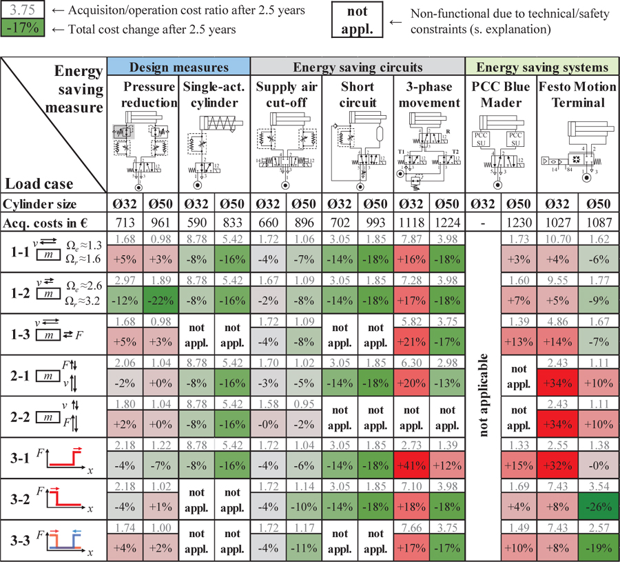
Since not for every ESC the payback point can be determined (e.g. a single-acting cylinder has inherently lower purchase price and energy consumption, resulting in a negative payback point compared to the standard circuit), the total costs of each ESC were calculated and compared for an observation period of 2.5 years instead. This payback period is reasonable for the energy-saving solutions according to a Germany-wide automation industry survey [92].
Table 3 presents the impact of all the ESCs on travel times and energy consumption compared to the standard circuit. White-font data correspond to the ESC-load combinations, for which either no significant energy saving is feasible from the theoretical analysis or no measurements were carried out for the safety reasons (in case of vertical mass movements, 2-1 and 2-2). These combinations where studied by means of simulation only. All other combinations (black-font data) were studied experimentally and the results shown in the Table 3 were derived from the measurements. The effect of using an ESC on the total cost of a drive after 2.5 years is summarised in Table 4.
As can be seen from Table 3, not all ESCs are applicable with all load cases. For instance, the retraction force of a single-acting cylinder is limited to the spring force, which may not be sufficient to pull the piston back against external retraction force in the cases 1-3 and 3-3.
Table 3 Change in performance and air consumption of energy-saving circuits in comparison to the standard meter-out circuit
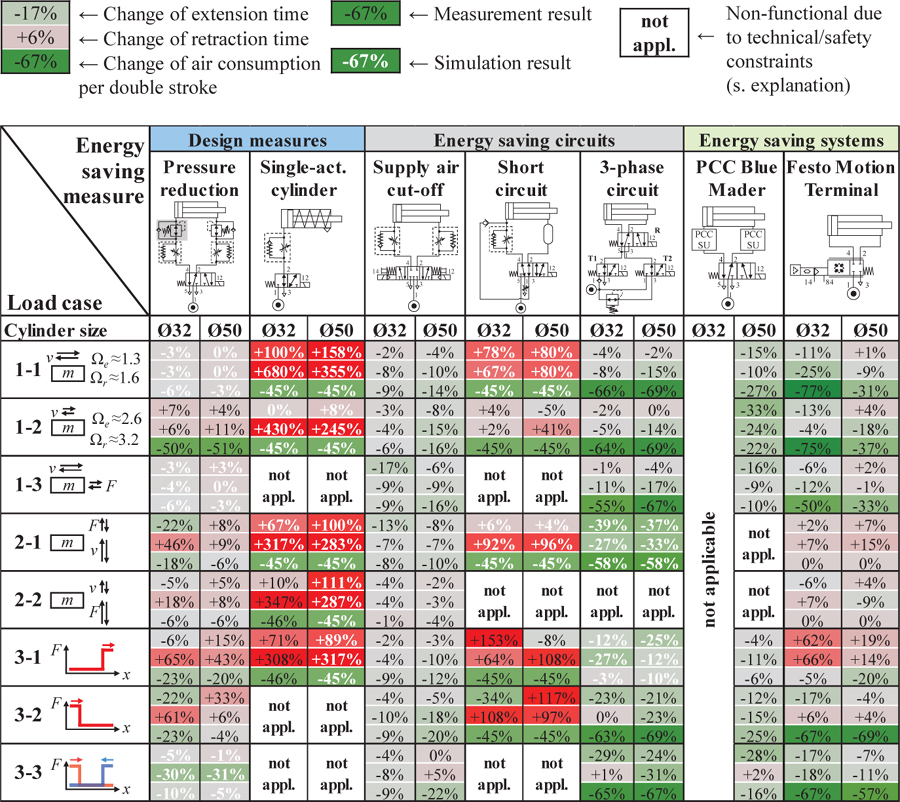
The absence of the integrated pneumatic end cushioning in single-acting cylinders makes the abrupt motion in 3-2 not possible without severe impact stress and therefore precludes the requirement . The short circuit, utilising a pneumatic spring for the return motion instead of the mechanical spring, faces the same lack of retraction force as the single-acting cylinder and hence is not applicable in the cases 1-3 and 3-3.
In case 2-2, the meter-out throttle opening of the short circuit undergoes two contradictive requirements: throttle conductance should be high enough to enable fast extension and small enough to prevent the shock when descending the mass. Both requirements concerning and cannot be met simultaneously in this load case.
The 3-phase movement circuit is also not applicable for high mass descending in case 2-2. The backpressure in the counteracting (lower) chamber is limited to the supply pressure due to the presence of the check valve in the braking and recuperation phase. This leads to the load mass falling down almost without any breaking or cushioning effect.
The further circuit, PCC Blue by Mader, is not applicable for any cylinders under Ø50. In PCC Blue’s teaching process, the cylinder can experience increased impact stress in the cushioning zone during initial strokes. Due to the risk of uncontrolled mass falling, this component was not tested on vertical load cases 2-1 and 2-2.
Table 4 Change in total cost of energy-saving circuits in comparison to the standard meter-out circuit
The pneumatic-mechanical solutions pressure reduction, single-acting cylinder, and short circuit show a performance loss with simultaneously reduced air consumption in all load cases. A double-sided pressure reduction in case 1-2 leads to a negligible performance loss, making this measure particularly suitable to compensate oversizing.
Application of the 3-phase movement circuit enables both significant energy and cost savings as well as improves the drive performance even in case of a well-sized reference. This higher dynamics is possible due to an intensive active deceleration of the moved mass, since the damping capability of this circuit is intrinsically higher than that of the integrated pneumatic end cushioning. Disadvantages of this circuit are high complexity of wiring and programming because of the number of additional proximity sensors and valves needed as well as high sensitivity to changes in mass load and positions of the proximity sensors.
The use of supply air cut-off in a meter-out throttling circuit can slightly improve both performance and energy efficiency without a major technical effort. The observed reduction in travel times is due to a slightly lower chamber pressure that is built up at the end of the stroke due to the cut-off in comparison to a standard circuit. Therefore, during the subsequent stroke, the counter chamber exerts less resistance, enabling faster acceleration. However, the achievable energy savings depend significantly on the dynamics of the pressure build-up in the cylinder chambers and in the volume between the pressure regulator and the directional valve, or with other words on the capacities and resistances between the pressure regulator, directional valve and the cylinder.
The use of the VTEM enables the greatest energy savings among the other ESCs: up to 77% compared with a well-sized reference. This benefit is, however, accompanied by high investment costs. The use of the PCC, although limited to cylinder sizes Ø50 upwards, also allows significant savings up to 28% even with well-dimensioned cylinders.
For horizontal well-dimensioned tasks (case 1-1), the application of energy saving systems is thus the only way to achieve significant energy savings without loss of performance. For oversizing (case 1-2), the use of a pressure regulator is particularly attractive and cost-efficient. For a horizontal movement with a counterforce over the whole stroke (case 1-3), cutting off the supply air is the most cost-effective solution that brings moderate improvement in performance and energy efficiency. Much higher savings are achievable with the VTEM and PCC in this case, which are in total more expensive for the smaller cylinder sizes.
For vertical tasks 2-1 and 2-2, typically modest energy savings of around 10% can be achieved with negligible impact on performance. The same applies to case 3-1, for which a high end force is required. Many ESCs are accompanied by a reduced pressure level, which significantly slows down the extension times of these solutions. In load cases 3-2 and 3-3, energy-saving systems in particular show significant savings along with improved performance.
In terms of TCO, ESCs equipped with smaller cylinders (Ø32) often incur higher total costs as a result their low absolute air consumption, leading to longer amortization periods compared to ESCs with larger cylinders. This manifests itself in a higher acquisition-operation cost ratio. Short circuit, single-acting cylinder (available only for shorter strokes), as well as 3-phase movement circuit with larger cylinders are among the most cost-effective solutions due to their high energy efficiency.
7 Conclusions
This paper presents the results of a comparative analysis of various energy-saving circuits (ESCs) applied in different load cases. The purpose is to provide the industrial users of pneumatics with an experimentally verified information about the applicability of the energy saving measures, their impact on cylinder performance and the real cost-saving potential. The results rely on experimental measurements carried out on two double-acting cylinders Ø32200 and Ø50200, and a single-acting cylinder Ø3250 (the single-acting cylinder Ø5050 was simulated only). The standard meter-out throttling with the shortest transition times possible (i.e. maximum performance) was used as a reference for comparison of the ESCs. To summarize the study, the following statements can be made:
• In case of a well-sized cylinder, traditional energy-saving circuits yield minimal savings. Energy-saving systems such as the off-the-shelf components VTEM by Festo SE & Co. KG or PCC Blue by Mader GmbH, however, offer significant energy savings up to 77% even in such scenarios.
• In case of an oversized cylinder, the installation of a pressure regulator to reduce pressure levels becomes a viable option. By employing energy-saving systems, even greater savings can be achieved.
• The supply air cut-off circuit yields moderate savings (up to 10%) for all load cases at reasonable cost. However, its real energy savings depend strongly on the time needed to equalise the pressure drop caused by components between compressed-air maintenance unit and cylinder.
• Implementing a short circuit can lead to substantial energy savings (up to 45%), but entails significantly increased travel times.
• For special load cases (e.g. 1-3, 3-1 to 3-3), traditional energy-saving circuits are not an optimal solution, as they often exceed acceptable travel time limits.
• Integrated pneumatic end cushioning is essential for a smooth deceleration of the inertial mass within the limits of elastomeric shock absorber’s kinetic energy in the cylinder end cup. It ensures short transition times by eliminating oscillations caused by under- or overdamping. Energy-saving systems such as VTEM or PCC, as well as the 3-phase movement circuit greatly enhance damping capacity, improving cylinder dynamics in almost all load cases. This allows to handle larger masses with shorter transition times, leading to both higher performance and lower energy consumption. It is relevant not only for handling tasks, but also for load-free return strokes in full-force applications.
In conclusion, the correct cylinder sizing remains the basic premise for energy-efficient pneumatics. This is especially crucial for cylinder drives with small filling volumes, as their low absolute air consumption would lead to a long amortization time of the ESCs. In these terms, correct sizing is the most cost-effective energy-saving measure for small cylinders. Retrofitting an oversized cylinder can be accomplished using a simple and cost-effective pressure regulator.
For medium and large cylinders, especially with short travel times, implementing sophisticated cylinder control components (VTEM, PCC, 3-phase movement circuit) offers several benefits. These include significant reduction in air consumption and thus energy costs, improved dynamic performance, sometimes even allowing an under-sizing of the cylinder, and time savings through self-adaptive throttle adjustment for fluctuating loads.
Although the study has covered the majority of the ESCs known to the authors and the most common load cases, its results still should be used with caution if applied to other more specific load cases. The significance of the study, especially regarding TCO savings, may also be limited for cylinders featuring shorter strokes and/or piston diameters smaller than 32 mm due to different proportions of acquisition and operating costs.
References
[1] Statista Research Department, ‘Verteilung des Stromverbrauchs in Deutschland nach Verbrauchergruppen 2021/2022’, published 03.08.2023, available online: https:/de.statista.com/statistik/daten/studie/236757/umfrage/stromverbrauch-nach-sektoren-in-deutschland/ (accessed on 03 February 2024).
[2] P. Radgen, E. Blaustein, ‘Compressed Air Systems in the European Union, Energy, Emissions, Savings Potential and Policy Actions’, Fraunhofer Institute for Systems Technology and Innovation, Stuttgart, Germany, 2001.
[3] S. Fritz, ‘Verfahren zur Erkennung sowie Diagnose von Fehlern in pneumatischen Systemen und Komponenten’, PhD dissertation, Aachen, Germany, 2011.
[4] T. Radermacher, M. Merx, A. Sitte, V. Boyko, M. Unger, ‘Potenzialstudie Energie-/Kosteneinsparung in der Fluidtechnik’, final report No. 37EV181030, TU Dresden, University of Stuttgart, Germany, 2021.
[5] N. N., ‘Energiereduktion in der Vakuumhandhabung durch Reduzierung von Totvolumina mittels bionischer Wirkprinzipien’, final report No. 03ET1559A-D, 2021.
[6] European Commission, ‘Stepping up Europe’s 2030 climate ambition. Investing in a climate-neutral future for the benefit of our people’, COM/2020/562, 2020.
[7] N. N., ‘Energieeffizienz in der Produktion im Bereich Antriebs- und Handhabungstechnik (EnEffAH)’, final report No. 0327484A-E, 2012.
[8] R. Dindorf, ‘Estimating Potential Energy Savings in Compressed Air Systems’, Procedia Engineering, 39, pp. 204–211, 2012.
[9] A. McKane, A. Hasanbeigi, ‘Motor systems energy efficiency supply curves: A methodology for assessing the energy efficiency potential of industrial motor systems’, Energy Policy, Vol. 39, Issue 10, 2011.
[10] W. Gauchel, ‘Energiesparende Pneumatik. Konstruktive sowie schaltungs- und regelungstechnische Ansätze’, O+P Fluidtechnik, pp. 33–39, 1/2006.
[11] R. Saidur, N. A. Rahim, M. Hasanuzzaman, ‘A review on compressed-air energy use and energy savings’, Renewable and Sustainable Energy Reviews, 14, pp. 1135–1153, 2010.
[12] D. Šešlija, I. Milenkovic, S. Dudić, J. Šulc, ‘Improving Energy Efficiency in Compressed Air Systems. Practical Examples’, THERMAL SCIENCE, Vol. 20, Suppl. 2, pp. 335–370, 2016.
[13] J. Hepke, ‘Energetische Untersuchung und Verbesserung der Antriebstechnik pneumatischer Handhabungssysteme’, PhD dissertation, TU Dresden, Germany, 2016.
[14] P. Harris, G. O’Donnell, T. Whelan, ‘Energy Efficiency in Pneumatic Production Systems: State of the Art and Future Directions’, Proc. Of the 19th CIRP International Conference on Life Cycle Engineering, Berkeley, USA, 2012.
[15] M. Doll, R. Neumann, O. Sawodny, ‘Dimensioning of pneumatic cylinders for motion tasks’, Int. J. of Fluid Power, 16:1, pp. 11–24, 2015.
[16] E. Rakova, J. Weber, ‘Exonomy analysis for the selection of the most cost-effective pneumatic drive solution’, Proc. of the 9th FPNI Ph.D. Symposium on Fluid Power, FPNI2016-1518, Florianópolis, Brazil, 2016.
[17] V. Vigolo, V. J. De Negri, ‘Sizing optimization of pneumatic actuation systems through operating point analysis’, J. Dyn. Syst. Meas. Control, Vol. 143, No. 5, 2021.
[18] V. Boyko, S. Hülsmann, J. Weber, ‘Comparative Analysis of Actuator Dimensioning Methods in Pneumatics’, Proc. of the ASME/BATH 2021 Symposium on Fluid Power and Motion Control, Online, 2021.
[19] V. Boyko, J. Weber, A. Raisch, O. Sawodny, S. Hülsmann, R. Volk, J. Ohrem, J. Lorenz, H.-M. Schwarz, J. Müller, ‘Anwenderorientierter Einsatz von energieeffizienter Antriebstechnik in der Produktion“ (EnAP)’, final report No. 03ET1385A-E, 2021.
[20] N. N., ‘SimulationX User Manual’, ESI ITI GmbH, 2022.
[21] DSHplus by FLUIDON GmbH, available online: https:/fluidon.com/en (accessed on 03 February 2024).
[22] H. Fleischer. ‘Manual of pneumatic systems optimization’, McGraw-Hill, New York, 1995.
[23] N. N., ‘Air Saving Valve. Series ASR/ASQ’, SMC Corporation Datasheet, state 10/2022.
[24] L. Dvořák, K. Fojtášek, ‘Pressure Regulators as Valves for Saving Compressed Air and their Influence on System Dynamics’, Web of Conferences 92, 2015.
[25] Š. Chmura, ‘Energeticky úsporné systémy v pneumatickıch mechanismech’, bachelor’s thesis, Technical University of Ostrava, Czech Republic, 2019.
[26] Motion App “ECO drive”, available online: https:/www.festo.com/gb/en/app/eco-drive.html (accessed on 03 February 2024).
[27] V. Blagojević, D. Šešlija, S. Dudić, S. Randjelovic, ‘Energy Efficiency of Pneumatic Cylinder Control with Different Levels of Compressed Air Pressure and Clamping Cartridge’, Energies, 13(14), 3711, 2022.
[28] S. Dudić, V. Reljić, D. Šešlija, N. Dakić, V. Blagojević, ‘Improving Energy Efficiency of Flexible Pneumatic Systems’, Energies, 14(7), 1819, 2021.
[29] O. Reinertz, K. Schmitz, ‘Optimized Pneumatic Drives Through Combined Downstream and Adaptive Upstream Throttling’, Proc. of the ASME/BATH 2020 Symposium on Fluid Power and Motion Control, Online, 2020.
[30] C. Reese, O. Reinertz, K. Schmitz, ‘Energy Savings Through Pneumatic-Mechanical Adaptive Upstream Throttling and Supply Shut-Off on Downstream Throttled Drives’, Proc. of the 13th International Fluid Power Conference (13. IFK), Aachen, Germany, 2022.
[31] N. N., ‘Integrated valve and actuator (IVAC) clean line unit’, IMI Norgren Datasheet, state 05/2016.
[32] N. N., ‘Compact Cylinder With Solenoid Valve. Series CVQ’, SMC Corporation Datasheet, state 10/2022.
[33] N. N., ‘Standards-based cylinder DNC-V’, Festo SE & Co. KG Datasheet, state 07/2022.
[34] N. N., ‘Anbauventile ABV-MV’, SCHUNK GmbH & Co. KG Datasheet, state 10/2022.
[35] D. Otis, ‘Reducing Compressed Air Consumption by Utilizing Expansion Energy during the Actuation of a Pneumatic Cylinder’, Proc. of the 45th National Conference of Fluid Power, Chicago, USA, 1992.
[36] E. Köhler, E. Zipplies, M. Nestler, G. Rosenbaum, ‘Verfahren zur Energiereduzierung an pneumatischen Antrieben’, German patent No. DE19721759A1, filed 24.05.1997, issued 26.11.1998.
[37] M. Ohmer, ‘Fluidtechnisches System’, German patent No. DE1020090 17879A1, filed 17.04.2009, issued 21.10.2010.
[38] M. Y. Mohd Yusop, ‘Energy Saving for Pneumatic Actuation Using Dynamic Model Prediction’, PhD dissertation, Cardiff University, UK, 2006.
[39] M. Doll, O. Sawodny, ‘Energy Optimal Open Loop Control of Standard Pneumatic Cylinders’, Proc. of the 7th International Fluid Power Conference (7. IFK), Aachen, Germany, 2010.
[40] K. Janiszowski, M. Kuczyński, ‘Energy Saving Control in Low Cost Pneumatic Positioning Systems’, Proc. of the 15th International Conference on Methods and Models in Automation and Robotics, Miȩdzyzdroje, Poland, 2010.
[41] M. Doll, R. Neumann, O. Sawodny, ‘Energy Efficient Use of Compressed Air in Pneumatic Drive Systems for Motion Tasks’, Proc. of the 2011 International Conference on Fluid Power and Mechatronics, pp. 340–345, Bejing, China, 2011.
[42] S. Merkelbach, H. Murrenhoff, ‘Exergy Based Analysis of Pneumatic Air Saving Measures’, Proc. of the ASME/BATH 2015 Symposium on Fluid Power and Motion Control, Chicago, Illinois, USA, 2015.
[43] A. Pfeffer, T. Glück, A. Kugi, ‘Soft landing and disturbance rejection for pneumatic drives with partial position information’, Proc. of the 7th IFAC Symposium on Mechatronic Systems & 15th Mechatronics Forum International Conference, Vol. 49, pp. 559–566, Loughborough, UK, 2016.
[44] D. Padovani, E. J. Barth, ‘Exploiting Valve Timing for Pneumatic Energy Savings’, Proc. of the BATH/ASME 2018 Symposium on Fluid Power and Motion Control, Bath, UK, 2018.
[45] H. Du, W. Xiong, Z. Jiang, Q. Li, L. Wang, ‘Energy efficiency control of pneumatic actuator systems through nonlinear dynamic optimization’, J. of Cleaner Production, Vol. 184, pp. 511-519, 2018.
[46] A. Raisch, S. Hülsmann, O. Sawodny, ‘Saving Energy by Predictive Supply Air Shutoff for Pneumatic Drives’, Proc. of the 2018 European Control Conference (ECC), Limassol, Cyprus, 2018.
[47] A. Pfeffer, T. Glück, F. Schausberger, A. Kugi, ‘Control and estimation strategies for pneumatic drives with partial position information’, Mechatronics, Vol. 50, pp. 259–270, 2018.
[48] H. Du, C. Hu, W. Xiong, L. Wang, ‘Applicability of bridge-type pneumatic energy-saving systems and its experimental validation’, Heliyon, Vol. 6, issue 5, 2020.
[49] H. Du, C. Hu, W. Xiong, Z. Jiang, L. Wang, ‘Energy optimization of pneumatic actuating systems using expansion energy and exhaust recycling’, J. of Cleaner Production, Vol. 254, 2020.
[50] H. Du, X. Wei, L. Wei, ‘A Nonlinear Dynamic Optimization Algorithm of a Novel Energy Efficient Pneumatic Drive System’, Int. J. of Control, Automation and Systems, Vol. 20, Issue 5, pp. 1593–1604, 2022.
[51] T. Glück, W. Kemmetmüller, A. Pfeffer, A. Kugi, ‘Pneumatic pulse-width modulated pressure control via trajectory optimized fast-switching electromagnetic valves’, Proc. of the 13th Mechatronics Forum, International Conference, Vol. 3/3, pp. 692–699, Linz, Austria, 2012.
[52] D. Šešlija, S. Èajetinac, V. Blagojević, J. Šulc, ‘Application of pulse width modulation and by-pass valve control for increasing energy efficiency of pneumatic actuator system’, Proc. of the Institution of Mechanical Engineers, Part I: Journal of Systems and Control Engineering, Vol. 232, Issue 10, pp. 1314–1324, 2018.
[53] P. Harris, S. Nolan, G. E. O’Donnell, ‘Energy optimisation of pneumatic actuator systems in manufacturing’, J. of Cleaner Production, Vol. 72, pp. 35–45, 2014.
[54] C. Hu, W. Xiong, H. Du, Z. Jiang, ‘Research on A Bridge-Type Energy-Saving Circuit Based on Pneumatic Vertical Motion System’, Proc. of the 2019 IEEE 8th International Conference on Fluid Power and Mechatronics (FPM), pp. 101–106, 2019.
[55] N. N., ‘Vorrichtung zur Betätigung eines doppeltwirkenden pneumatischen Antriebes’, German utility patent No. DE202012102190U1, filed 14.06.2012, issued 20.08.2012.
[56] W. Krämer, ‘Pneumatische Steuerung mit Druckluftrückführung’, German utility patent No. DE202015003307U1, filed 05.05.2015, issued 06.08.2015.
[57] H. Hayashi, N. Hayashi, ‘Fluid control valve’, WO patent No. WO/2017/073439, filed 20.10.2016, issued 04.05.2017.
[58] S. Ito, ‘Drive method and drive device for fluid pressure cylinder’, European patent No. EP3597933A1, filed 25.07.2018, issued 22.01.2020.
[59] J. Brenner, ‘Ausgleichsventil, Ventilsystem und Pneumatiksystem’, German patent No. DE102018003000A1, filed 12.04.2018, issued 17.10.2019.
[60] M. Heitmann, T. Hergenröther, ‘Fluidrückführvorrichtung für einen doppeltwirkenden Zylinder und Verfahren zum Betreiben eines solchen Zylinders’, German patent No. DE102019121433A1, filed 08.08.2019, issued 11.02.2021.
[61] V. Blagojević, P. Lj. Janković, ‘Advantages of Restoring Energy in the Execution Part of Pneumatic System with Semi-Rotary Actuator’, THERMAL SCIENCE, Vol. 20, suppl. 5, pp. 1599–1609, 2016.
[62] A. Yang, J. Pu, C. B. Wong, P. Moore, ‘Control Methods for Energy-Efficient Pneumatic Servos Employing Asymmetric Cylinders’, Proc. of the ASME 7th Biennial Conference on Engineering Systems Design and Analysis, Vol. 2, pp. 409–414, Manchester, UK, 2004.
[63] X. Shen, M. Goldfarb, ‘Energy Saving in Pneumatic Servo Control Utilizing Interchamber Cross-Flow’, ASME J. Dyn. Sys., Meas., Control, 129(3), pp. 303–310, 2007.
[64] A. Yang, J. Pu, C. B. Wong, P. Moore, ‘By-pass valve control to improve energy efficiency of pneumatic drive system’, Control Engineering Practice, Vol. 17, Issue 6, pp. 623–628, 2009.
[65] V. Blagojević, D. Šešlija, M. Stojiljković, ‘Cost effectiveness of restoring energy in execution part of pneumatic system’, Journal of Scientific & Industrial Research, Vol. 70, pp. 170–176, 2011.
[66] V. Blagojević, D. Šešlija, M. Stojiljković, S. Dudić, ‘Efficient control of servo pneumatic actuator system utilizing by-pass valve and digital sliding mode’, Sadhana Indian Academy of Science, Vol. 38, Part 2, pp. 187–197, 2013.
[67] L. Endler, V. J. De Negri, E. B. Castelan, ‘Compressed air saving in symmetrical and asymmetrical pneumatic positioning systems’, Proc. of the Institution of Mechanical Engineers, Part I: Journal of Systems and Control Engineering, 229(10), pp. 957–969, 2015.
[68] M. Heitmann, F. Rein, ‘Energy efficiency in pneumatics with the ’Air Saving Box’: the revolutionary plug & play solution from SMC’, Proc. of the 12th International Fluid Power Conference (12. IFK), Dresden, Germany, 2020.
[69] E. Schneider, ‘Pneumatic circuit for rapidly transferring fluid under pressure from a work cylinder to a storage tank for subsequent use’, US patent No. US000003400636A, filed 12.04.1966, issued 10.09.1968.
[70] E. Köhler, E. Zipplies, M. Nestler, G. Rosenbaum, ‘Vorrichtung zur Energiereduzierung und Verbesserung der Dynamik an pneumatischen Anlagen’, German patent No. DE000010011947A1, filed 11.03.2000, issued 13.09.2001.
[71] M. Jianguo, T. Xin, Y. Qihui, Z. Jianwei, ‘Exhaust gas recovery-based pneumatic integrated system and control method thereof’, Chinese patent No. CN000110848208A, filed 02.12.2019, issued 28.02.2020.
[72] Y. Shi, X. Li, Y. Teng, ‘Research on pneumatic cylinder’s exhausted-air reclaiming control devices’, Proc. the 6th JFPS International Symposium on Fluid Power, pp. 558–563, Tsukuba, Japan, 2015.
[73] M. Novaković, D. Šešlija, S. Èajetinac, M. Todorovic, ‘Impact of Capturing Used Air on the Dynamics of Actuator Drive’, CEAI, Vol. 17, No. 2, pp. 82–89, 2015.
[74] Q. Yu, J. Zhai, Q. Wang, X. Zhang, X. Tan, ‘Experimental Study of a New Pneumatic Actuating System Using Exhaust Recycling’, Sustainability, 13(4):1645, 2021.
[75] M. Šešlija, V. Reljić, D. Šešlija, S. Dudić, N. Dakić, Z. Jovanović, ‘Reuse of Exhausted Air from Multi-Actuator Pneumatic Control Systems’, Actuators, 10(6):125, 2021.
[76] Y. Takakuwa, H. Asahara, K. Kadota, A. Iwamoto, N. Shinjo, K. Someya, A. Kazama, ‘Driving method and driving device of fluid pressure cylinder’, WO patent No. WO/2018/056036, filed 04.09.2017, issued 29.03.2018.
[77] Y. Takakuwa, H. Asahara, K. Monden, A. Iwamoto, N. Shinjo, K. Someya, A. Kazama, ‘Fluid pressure cylinder’, WO patent No. WO/2018/056037, filed 04.09.2017, issued 29.03.2018.
[78] G. Harimoto, M. Senco, Y. Fujiwara, ‘Fluid circuit selection system and fluid circuit selection method’, US patent No. US020210246913A1, filed 07.06.2019, issued 10.12.2020.
[79] N. N., ‘Air Cylinder/Air Saving Type CP96-X3153/X3154’, SMC Corporation Datasheet, state 10/2022.
[80] G. Krytikov, M. Strizhak, V. Strizhak, ‘The Synthesis of Structure and Parameters of Energy Efficient Pneumatic Actuator’, Eastern-European Journal of Enterprise Technologies, Vol. 1, No. 7 (85), 2017
[81] G. Krytikov, M. Strizhak, V. Strizhak, ‘Improving Power Efficiency of Pneumatic Logistics Complex Actuators through Selection of a Rational Scheme of Their Control’, Eastern-European Journal of Enterprise Technologies, Vol. 2, No. 8 (92), pp. 43–49, 2018.
[82] V. Boyko, J. Weber, ‘Combinations of energy saving measures in pneumatics’, Proc. of the 12th International Fluid Power Conference (12. IFK), Dresden, Germany, 2020.
[83] N. N., ‘Motion Terminal VTEM’, Festo SE & Co. KG Datasheet, state 04/2022.
[84] Mader GmbH, ‘Digitalisierung der Pneumatik mit intelligenter Erweiterung für Zylinder – PCC Blue’, available online: https:/www.mader.eu/loesungen/druckluft-digitalisieren/pcc-blue (accessed on 03 February 2024).
[85] N. N., ‘Pressure Regulator VRPA’, Festo SE & Co. KG Datasheet, state 10/2022.
[86] N. N., ‘Air Saving Speed Controller. AS-R/AS-Q Series’, SMC Corporation Datasheet, state 10/2022.
[87] K. Stoll, ‘Pneumatische Steuerungen: Einführung und Grundlagen’, Würzburg, Vogel Buchverlag, 1999.
[88] S. Hesse, ’99 Examples of Pneumatic Applications’, Blue Digest on Automation, Festo AG & Co., 2000.
[89] S. Woo, D. L. O’Neal, Y, M. Hassen, ‘Enhancing the Lifetime of the Pneumatic Cylinder in Automatic Assembly Line Subjected to Repeated Pressure Loading’, Metals, 12, 35, 2022.
[90] F. Nazarov, J. Weber, ‘Modelling, Simulation and Validation of the Pneumatic End-Position Cylinder Cushioning’, Proc. of the 17th Scandinavian International Conference on Fluid Power (SICFP), pp. 248–265, Linköping, Sweden, 2021.
[91] F. Nazarov, J. Weber, ‘Heat Transfer Model of Pneumatic End-Position Cylinder Cushioning’, Int. J. of Fluid Power, Vol. 23, Issue 1, 2021.
[92] S. Hülsmann, R. Volk, V. Boyko, A. Raisch, J. Weber, O. Sawodny, ‘Energieeffiziente Antriebstechnik in der Produktion – Herausforderungen bei der Umsetzung’, O+P Fluidtechnik, pp. 38–41, 9/2020.
Biographies

Vladimir Boyko holds a M.Eng. degree in Mechanical Engineering from the University of Applied Sciences Jena, Germany. Since 2018 he has been working as a research assistant at the Chair of Fluid-Mechatronic Systems (Fluidtronics), Institute of Mechatronic Engineering, TUD Dresden University of Technology, Germany. His current research fields include pneumatics and energy efficiency.

Fedor Nazarov received the bachelor’s and master’s degrees in hydraulic, pneumatic, and vacuum system engineering from the South Ural State University in 2014 and 2016 respectively. Since early 2017 to this day, he is working as a research assistant at the Chair of Fluid-Mechatronic Systems (Fluidtronics), Institute of Mechatronic Engineering, TUD Dresden University of Technology. His research areas include simulation and optimisation of pneumatic systems and their components with regard to energy efficiency and performance.

Wolfgang Gauchel completed his mechanical engineering studies at RWTH Aachen with a diploma in 2001. After that he worked as a research assistant at the Institute of Fluid Power Drives and Controls (IFAS) at RWTH Aachen, where he finished his PhD in 2006 in the field of servopneumatic gripping technology. After that he started his industrial career in the research department of Festo Se & Co. KG in Esslingen, Germany. Alongside his work, he studied economics at the Fernuni Hagen and received the bachelor’s degree in 2012. Currently he is Head of Research Circular Economy and Efficiency.

Rüdiger Neumann has studied mechanical engineering in Paderborn and Nottingham and got his diploma in 1986. After working as a research associate at the University of Paderborn and Ulm he received his PhD in 1995. Since 1996 he works as an engineer of automation and control in the research department of the Festo SE & Co. KG, where he is now head of the department for Robotics and Control. His key activities are the control of pneumatic and electrical servo drives, as well as control of multi axes systems and robots.

Matthias Doll received his diploma degree in engineering cybernetics from the University of Stuttgart, Stuttgart, Germany, in 2009. After that he has been a research assistant at the Institute for System Dynamics (ISYS) at the University of Stuttgart and received his PhD in 2016. Since 2012, he is a research engineer at Festo SE & Co. KG, Esslingen, Germany. His main research interests include modelling and control of pneumatic drive systems with a focus on energy efficiency.

Jürgen Weber has been appointed in 2010 as a University Professor and the Chair of Fluid-Mechatronic Systems as well as the Director of the Institute of Fluid Power at the TUD Dresden University of Technology, Germany, and took on the leadership of Institute of Mechatronic Engineering in 2018. He finished his doctorate in 1991 and was an active Senior Engineer at the former Chair of Hydraulics and Pneumatics until 1997. This was followed by a 13-year industrial phase. Besides his occupation as the Head of the Department Hydraulics and Design Manager for Mobile and Tracked Excavators, starting in 2002, he took on responsibility for the hydraulics in construction machinery at CNH Worldwide. From 2006 onwards, he was the Global Head of Architecture for hydraulic drive and control systems, system integration and advance development CNH construction machinery.
International Journal of Fluid Power, Vol. 25_1, 27–58.
doi: 10.13052/ijfp1439-9776.2512
© 2024 River Publishers