Variable-Speed Pump-Controlled Three-chamber Cylinder System for Hydraulic Boom with Feed-Forward LADRC
Shuzhong Zhang1,*, Borui Wang1, Tatiana Minav2, Yiwen Tang1 and Yu Guo1
1Fujian Key Laboratory of Intelligent Machining Technology and Equipment (Fujian University of Technology), Fuzhou 350118, China
2Faculty of Engineering and Natural Sciences, ATME, Innovative Hydraulics and Automation, Tampere University, 33014 Tampere, Finland
E-mail: shuzhong_zhang@outlook.com; wang_borui@outlook.com; tatiana.minav@tuni.fi; tangsandi@163.com; ilovtz2021@163.com
*Corresponding Author
Received 28 November 2023; Accepted 18 April 2024
Abstract
With the increasing fossil fuel crisis and environmental degradation, energy-saving has been one of the fluid power transmissions’ priority research areas. In a conventional hydraulic boom, throttling and potential energy losses result in poor energy efficiency and extra rising of fluid temperature. To boost the energy efficiency of a hydraulic boom, this paper proposed a variable-speed pump-controlled three-chamber cylinder system for hydraulic boom with feed-forward plus linear active disturbance rejection control (LADRC). In the proposed system, chambers A and B of the three-chamber cylinder are controlled by two variable-speed fixed-displacement pumps and the third chamber C is connected to a hydraulic accumulator to balance the weight of the boom. Firstly, the model of the variable-speed pump-controlled three-chamber cylinder system is built in Matlab/Simulink. Further, the mechanical model of a 1-ton excavator is established, and the proposed system is applied to the boom. Secondly, a compound controller combining speed feed-forward and LADRC is designed. Thirdly, simulations were performed under boom up and down while keeping the arm and bucket cylinders fully retracted. The position control performance and energy consumption are analysed and compared. The results show that, compared to the PID and speed feed-forward PID control, the proposed controller has a lower position tracking error (less than 2.66%). Compared with the variable-speed pump-controlled differential cylinder system, the proposed system can save energy by 43.51% when considering energy recovery. Therefore, the proposed system has good position tracking performance and has the potential to be applied to different types of heavy-lifting equipment driven by hydraulic cylinders.
Keywords: Hydraulic boom, variable-speed pump-controlled, three-chamber cylinder, speed feed-forward, LADRC, energy recovery.
1 Introduction
Energy-saving and decarbonization of construction machinery is getting increasing attention [1]. Excavators are currently the most widely used construction machinery and their booms perform lifting and lowering actions cyclically during digging or levelling. The gravitational potential energy of boom is converted into heat energy during the lowering phase through the control valve, resulting in a low energy efficiency. Previous studies have shown that the energy efficiency of hydraulic excavators is only 20% and energy losses in the boom lifting hydraulic system exceed 50% [2, 3]. Therefore, recovering and reusing the potential energy of a hydraulic boom plays a significant role in energy saving and emission reduction in the construction machinery industry [4].
Thus, various system architectures were brought forward to boost the energy efficiency. Liebherr, a German company, has adopted the use of accumulators to improve the energy utilization efficiency of closed-loop hydraulic systems. By utilizing high-capacity accumulators to recover and reuse the potential energy of the load, fuel consumption can be reduced by 30% [5]. Tried et al proposed a hydraulic circuit that integrates an accumulator with a closed-loop hydraulic system. They employed a fuzzy self-tuning sliding mode control strategy and the results demonstrated an efficiency improvement of 22% to 59% [6]. In [7], the research result indicates that optimizing the operating trajectory of a loader can improve its diesel utilization rate by 15%. In [8], it demonstrates that employing a load-sensitive system to control the loader’s boom can reduce fuel consumption by 7% to 15% compared to traditional fixed-displacement pump oil supply systems. Hippalgaonkar et al. introduced a novel approach to improve the hydraulic system efficiency in excavators. They implemented a hydraulic accumulator to convert the potential energy of the boom during its descent into hydraulic energy. The recovered energy was then utilized to power the cooling system or other auxiliary devices, resulting in a significant reduction of fuel consumption by 27% [9]. Therefore, designing an energy recovery system to recover the potential energy of the boom is a potential way to achieve energy saving.
Moreover, the application of traditional Proportional-Integral-Derivative (PID) control usually can’t achieve satisfactory control performance under conditions of parameter uncertainty and external load disturbance [10]. Therefore, various position control methods were carried out to achieve construction automation and unmanned operation [11], such as nonlinear PID control [12], adaptive control [13], sliding mode control [14], and fuzzy control [15] which improved the control performance and robustness of the system to some extent. Seung et al. applied discrete sliding mode control to two variable speed pump control systems, enhancing the tracking control performance and reducing tracking errors [16]. Alleyne et al. implemented nonlinear adaptive robust control in force control for an actively controlled suspension with differential cylinder drive, demonstrating that nonlinear controllers can achieve better control performance compared to traditional linear controllers [17]. In [18], an adaptive hierarchical sliding mode control strategy was proposed, and neural networks were used to optimize the control parameters to have sufficient robustness under the uncertainty of system parameters. In [19], a third-order nonlinear active disturbance rejection control (ADRC) controller was designed to control the electro-hydraulic servo position system, and the results showed that the ADRC control outperformed the PID control in terms of anti-disturbance. In motor control, feed-forward control was used to predict the load changes and ADRC control was used to suppress the disturbances to the motor [20]. Aiming at the impact of load torque disturbance on permanent magnet synchronous motor (PMSM) control, a feed-forward compensation based ADRC strategy was proposed, effectively suppressing the speed fluctuations caused by load torque mutations [21].
ADRC does not rely on the precise model of the controlled object and has the ability of high control accuracy, fast response speed, and strong anti-disturbance. Hence, it has been widely used in fields of electric power systems, precision machinery, machining lathes, chemical processes and modern weapon systems [22, 23]. In addition, it has been successfully applied to the control of lifting equipment, such as various cranes, including overhead cranes [24], tower cranes [25], and ring cranes [26]. In response to the complex parameter tuning of the nonlinear ADRC in practical applications, Gao further linearized ADRC and proposed the linear active disturbance rejection control (LADRC), which not only retains the excellent control performance of ADRC but also simplifies the tuning problem to a bandwidth tuning problem, requiring only a few parameters to achieve satisfactory dynamic performance [27]. In summary, combining feed-forward control with ADRC can further improve the system positioning accuracy, suppress system disturbances, and achieve disturbance-free speed compensation.
In order to improve the position control performance and energy efficiency of the boom system, this paper proposes a variable-speed pump-controlled three-chamber cylinder system with feed-forward LADRC. Section 2 introduces the working principle of the proposed system, including recovery and utilization of the gravitational potential energy. Section 3 describes the modelling of the hydraulic system and mechanical system. Section 4 illustrates the design of the combined speed feed-forward and LADRC controller. In Section 5, the simulation and analysis were carried out to compare the position tracking performance of the system with PID, feed-forward PID, and speed feed-forward plus LADRC. Further, the energy efficiency of the variable-speed pump-controlled differential cylinder and three-chamber cylinder systems are comparatively analysed. Finally, conclusions are drawn in Section 6.
2 System Working Principle
Figure 1 shows the schematics of the proposed variable-speed pump-controlled three-chamber cylinder system for the boom. In the three-chamber cylinder, the cap-side chamber A and rod-side chamber B are connected with pump A and pump B, respectively, driven by a servo motor co-axially. The chamber C is constructed by a hollow rod and a fixed plunger on the cylinder, connected with the hydraulic accumulator B for balancing the weight of load. Another hydraulic accumulator A is installed as a low-pressurized tank. During boom lowering, the cylinder retracts, and the fluid in chamber C is charged into accumulator B under the action of the boom gravity, converting the potential energy into hydraulic energy. During boom lifting, the pressurized oil in accumulator B is discharged into chamber C, and the stored hydraulic energy is reutilized to balance the boom’s weight and to provide auxiliary power for boom lifting.
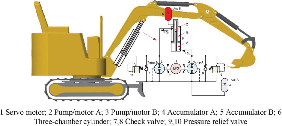
Figure 1 Schematics of the proposed variable-speed pump-controlled three-chamber cylinder system.
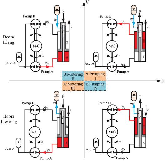
Figure 2 Four-quadrant operation of the variable-speed pump-controlled three-chamber cylinder.
Figure 2 shows the four-quadrant operation of the system. For an excavator boom, the system typically runs in two quadrants. When the boom is lifting, the system operates in quadrant I, pump A in pumping mode, and the hydraulic energy stored in accumulator B is converted into the potential energy of the boom to provide auxiliary power. When the boom is lowered, the system operates in quadrant III, pump A in motoring mode, and oil outputs from chamber C and charges into accumulator B, converting potential energy into hydraulic energy. Since chamber C is directly connected to accumulator B, the potential energy of the boom can be efficiently recovered and reutilized.
3 System Modelling
In this section, the excavator’s front attachment model is created in MATLAB/Simulink, including hydraulic system and mechanical system.
3.1 Hydraulic System Modelling
In previous research [28], a pump-controlled differential cylinder system was modelled in MATLAB/Simulink and validated. The hydraulic system’s schematics and test bench are shown in Figure 3, where the hydraulic accumulator A is utilized as a low-pressurized tank. Further, with the validated model, the model of the proposed variable-speed pump-controlled three-chamber cylinder system was created for an excavator boom, replacing the differential cylinder with the designed three-chamber cylinder and adding an accumulator B to balance the weight of boom. Tables 1 and 2 present the main components parameters of the two hydraulic systems, differential cylinder system and three-chamber cylinder system.
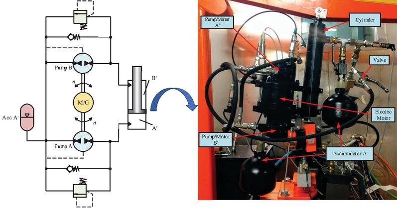
Figure 3 Pump-controlled differential cylinder system and the test bench.
Table 1 Main parameters of the differential cylinder system in the setup [28]
| No. | Component | Parameter | Value |
| 1 | Pump/motor A | Displacement (mL/rev) | 13.03 |
| 2 | Pump/motor B | Displacement (mL/rev) | 9.35 |
| 3 | Hydraulic accumulator A | Volume(L) | 0.7 |
| 4 | Differential cylinder | Dimensions (mm) | 6030@300 |
Table 2 Main parameters of the three-chamber cylinder system
| No. | Component | Parameter | Value |
| 1 | Pump/motor A | Displacement (mL/rev) | 13.03 |
| 2 | Pump/motor B | Displacement (mL/rev) | 9.35 |
| 3 | Hydraulic accumulator A | Volume(L) | 0.7 |
| 4 | Hydraulic accumulator B | Volume(L) | 0.7 |
| Pre-charged pressure (MPa) | 1 | ||
| 5 | Three-chamber cylinder | Dimensions (mm) | 605030@300 |
Compared to the differential cylinder system, the three-chamber cylinder system adds an additional accumulator and substitutes the three-chamber cylinder for the differential cylinder. Hence, component models regarding the accumulator and the three-chamber cylinder were built in the following subsections.
3.1.1 Three-chamber cylinder
Three-chamber cylinder schematics is demonstrated in Figure 1. The force balance equation of the cylinder is
| (1) |
where , and are the pressures of chamber A, B and C respectively, Pa; , and are the effective area of each chamber, m; m is the mass of piston rod; x is the piston displacement, m; is the friction force based on the LuGre model [28], N; is the load force, N.
The effective area of each chamber of the three-chamber cylinder is
| (2) | |
| (3) | |
| (4) |
where , and are the diameters of piston, rod and fixed plunger respectively, m.
The flow continuity equation for each chamber of the three-chamber cylinder is
| (5) | |
| (6) | |
| (7) |
where , and are the flow rates into chamber A, B and C respectively, m/s; , and are the total volumes of chamber A, B and C respectively, m; is the effective bulk modulus of hydraulic oil [28], Pa.
3.1.2 Hydraulic accumulator B
In the system, a bladder-type accumulator is selected for accumulator B and its gas state equation is
| (8) |
where is the pre-charged pressure, Pa; is the pre-charged gas volume, m; and are the pressure and volume of gas at any state, Pa and m; is the gas adiabatic constant.
As the accumulator B is connected to chamber C directly, from Equations (7) and (8), the pressure expression of the chamber C is derived as follows
| (9) |
where is the net volume of hydraulic oil flowing into and out from the accumulator, m.
3.2 Mechanical Model
A 1-ton micro excavator in the laboratory was used as the research object. The front attachment of the excavator was disassembled and the parameters of each part were measured, including mass, joint points, and centre of the mass. Based on the measured data, the three-dimensional model of the excavator was created. Further, the created CAD model was imported into the MATLAB/Simulink [29] and the mechanical model was created as shown in Figure 4.

Figure 4 Mechanical model.
3.3 Overall Front Attachment Model
Combining the hydraulic model and mechanical model, the overall front attachment model is built. Figures 5 and 6 demonstrate the boom driven by the variable-speed pump-controlled differential cylinder and the proposed three-chamber system respectively.
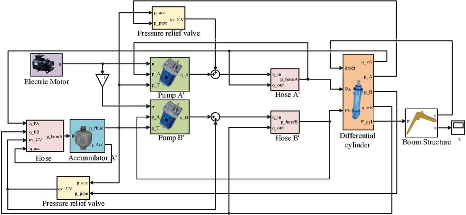
Figure 5 Differential cylinder system model in Matlab.

Figure 6 Three-chamber cylinder system model in Matlab.
4 Controller Design
To improve the anti-disturbance ability and to increase position tracking accuracy, a feed-forward LADRC is proposed and designed for the boom system. Firstly, a LADRC controller was designed to apply the extended state observer to observe and compensate the system state variables and overall disturbances, thereby enabling the system to effectively suppress disturbance and time-varying uncertainties. Secondly, a speed feed-forward controller is added to implement dynamic time lag compensation, ensuring accurate tracking of the given signal.
4.1 Controller Structure
The controller of the speed feed-forward LADRC is presented in Figure 7. In the controller, the target of the speed feed-forward control is to make the velocity of the boom converge to a reference signal that is computed based on the velocity . And the LADRC is a feedback control that aims to make the position of the boom track a desired reference position . Hence, a total control signal for the servo motor is acquired [30].
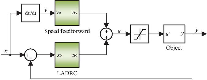
Figure 7 Block diagram of proposed controller.
4.2 LADRC Controller Structure
Active disturbance rejection control (ADRC) is a control algorithm that does not fully rely on the mathematical model of the controlled object. It considers the unknown disturbance and unmodelled part of the system as a total disturbance for estimation and dynamic compensation [31]. Compared to ADRC, linear active disturbance rejection control (LADRC) has reduced the number of tuning parameters from 10 to 3–4 for a single controller, making it easier to tune and more practical for practical applications. Therefore, the LADRC was put forward: (1) linearizing the nonlinear expanding state observer (NLESO) as a linear expanding state observer (LESO); (2) eliminating the tracking differential operator and replacing the feedback control law with a proportional-derivative (PD) controller. Figure 8 shows the closed-loop control system composed of a second-order LADRC. , , and the parameter in LESO are the tuning parameters to be determined.
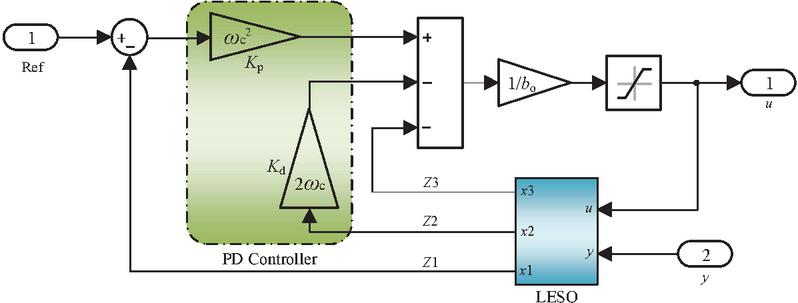
Figure 8 Control structure of LADRC controller.
The state-space equation of the variable-speed pump-controlled three-chamber system is derived based on the mathematical model of components. Based on Equations (1)–(7), the system state-space equation can be represented as
| (10) |
where
| (11) |
The ESO is the core part of ADRC. It can track the state variables in real-time, estimate the unmodelled dynamics of the system and unknown external disturbances. For a nth-order nonlinear controlled object, the n-order system can be expanded into the following -order system:
| (12) |
where is the system state variable; is system input; is the control parameter; is the system output; is an external perturbation; is the total unmodelled dynamic term of the system.
Based on the original NLESO, an improvement is made by replacing the previous nonlinear function with the observer error , resulting in the following LESO:
| (13) |
Based on Equation (13), defining the state variable , then the system state-space equation is
| (14) |
where f is the total system disturbance.
Based on this, the LESO can be represented as
| (15) |
where is the error between the output position and the estimated position; , and are the gain coefficient of output error; , and are the estimated values of the system’s state variables.
Further relates the parameters of the PD controller and the LESO to their bandwidths, with only three parameters, namely, the controller bandwidth , the observer bandwidth and the system characteristic , need to be tuned to obtain satisfactory dynamic performance. The relevant parameter configurations are as follows.
| (16) |
5 Simulation Results and Analysis
Figure 9 shows the multi-domain model of the proposed boom system, consisting of control hydraulic system and multibody. According to the general LADRC parameter tuning method [32], the parameters are finally set as , and . During the simulation, the arm and bucket are keeping fully retracted.
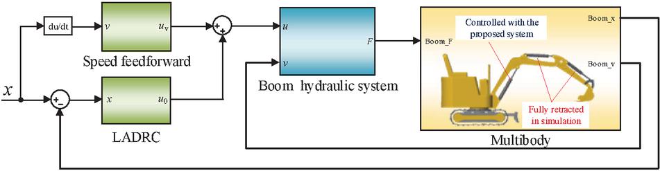
Figure 9 Overall system model.
5.1 Comparison of Position Tracking with PID, Feed-Forward PID and Feed-Forward LADRC
Figure 10 shows the position tracking curves and tracking error curves of the boom under different controllers. In the simulation, the boom descends to its lowest position during phase I, stays stationary in phase II, and rises to the initial position in phase III. Three types of controllers (PID, feed-forward PID and feed-forward LADRC) are applied to the three-chamber cylinder system, respectively.
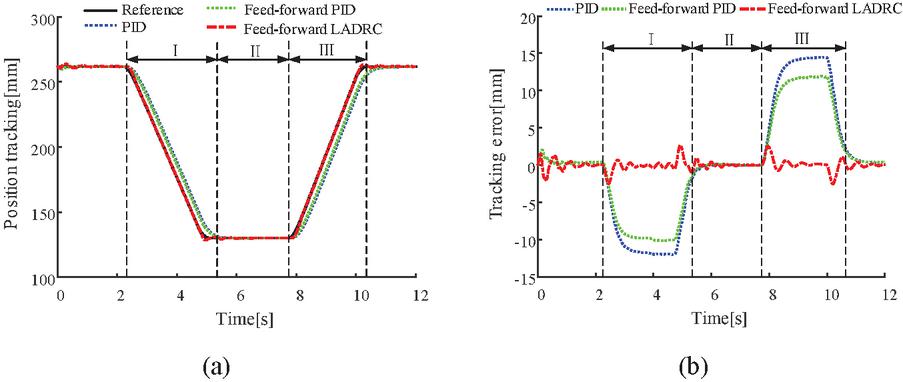
Figure 10 The position tracking of the boom (a) position tracking; (b) tracking error.
Figure 11 shows the comparisons of position tracking errors under different controllers. The maximum error, mean error and root mean square error (RMSE) of the feed-forward LADRC controller are 2.66 mm, 1.23 mm and 0.82 mm, respectively, much lower than the other two controllers. The maximum error is reduced by 81.62% and 77.68%, the mean error by 77.87% and 73.03% and the RMSE by 86.08% and 84.56%. Therefore, the tracking performance of the feed-forward LADRC outperforms that of the PID and feed-forward PID.

Figure 11 Comparison of position tracking error with different controllers.
Figure 12 illustrates the position and pressure levels of the three-chamber cylinder. As chamber C of the three-chamber cylinder and accumulator B are connected directly, their pressures are basically equal. In the phase of the boom down, the oil discharges from chamber C and goes into the accumulator B and the pressure of the accumulator rises from 1 MPa to 3 MPa. Therefore, the potential energy of the boom is converted into hydraulic energy and stored in the accumulator B. During lifting, the oil discharges from the accumulator B and flows into chamber C. As the volume of oil in accumulator B discharges, the pressure decreases from 3 MPa to 1 MPa, and energy stored in the accumulator is directly converted into the potential energy of the boom.
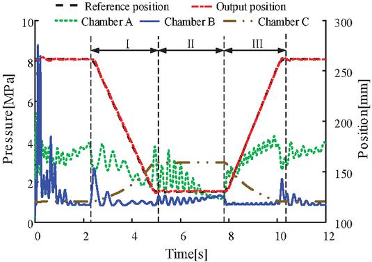
Figure 12 Position and pressure curves for three-chamber cylinder.
5.2 Energy Consumption Analysis with Feed-Forward LADRC
The power consumption of each component in the system can be calculated using the corresponding formulas in Table 3.
Table 3 Utilized equation for calculation
| Equation | Symbol |
| -power of the cylinder | |
| -energy consumed by the cylinder | |
| -pump pressure difference | |
| -pump flow rate | |
| -power of the pump | |
| -energy consumed by the pump | |
| -energy input to the pump when motoring | |
| -power of accumulator | |
| -power of accumulator | |
| -power consumed by the electric motor | |
| and 0.9 is the efficiency of electric motor | |
| -power regenerated by the electric motor | |
| -energy consumed by the electric motor | |
| -energy regenerated by the electric motor | |
| -system efficiency with differential cylinder | |
| -system efficiency with three-chamber cylinder |
Figure 13 shows the power curves of each component of the differential cylinder system and three-chamber cylinder system.
Figure 13(a) shows the power curves of each component of the differential cylinder system. In phase I, pump A operates in motoring mode, and the peak power of the servo motor under generating mode is 0.34 kW. Theoretically, 0.33 kJ of electrical energy can be recovered. In phase III, the peak power of the servo motor in motoring mode is 0.72 kW. In a working cycle, servo motor energy consumption is about 1.63 kJ.
Figure 13(b) shows the power curves of each component of the three-chamber system. In phase I, pump A runs in motoring mode, and the peak power of the servo motor is 0.26 kW. About 0.30 kJ of electrical energy can be recovered during this stage. In phase III, the peak power of the servo motor is 0.52 kW. During a working cycle, the servo motor consumes about 1.34 kJ. The peak power of the servo motor decreases from 0.72 kW to 0.52 kW, resulting in a decrease of 27.77% in system peak power and a corresponding reduction in energy consumption.
Figure 14 shows the energy consumption distribution of different drive systems. Compared with the differential cylinder system, the proposed system that the potential energy of the boom can be recovered and reutilized.
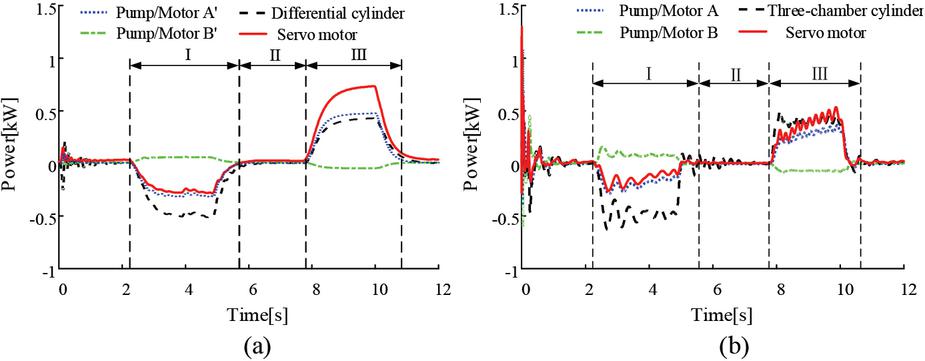
Figure 13 Power consumed by the components (a) differential cylinder; (b) three-chamber cylinder.
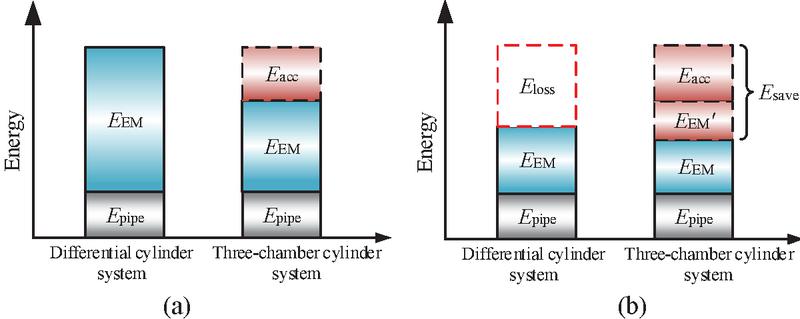
Figure 14 Energy consumption composition of the two systems (a) boom lift; (b) boom down.
Figure 15 shows the accumulator B power and energy of the three-chamber cylinder system.
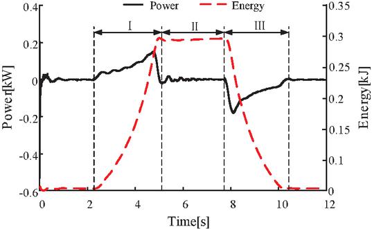
Figure 15 Power and energy of accumulator B in three-chamber cylinder system.
In phase I of the boom down, the gravitational potential energy is converted into hydraulic energy stored in accumulator B for potential energy recovery. The peak power is 0.17 kW, and the energy that can be recovered in this stage is 0.29 kJ. During lifting, converting stored hydraulic energy into gravitational potential energy to achieve energy recovery and reuse. Because the boom moves the same distance in the lower and upper ranges, the energy collected and released by the accumulator B is roughly the same.
Figure 16 compares the energy consumption of the differential cylinder system and the three-chamber cylinder system.
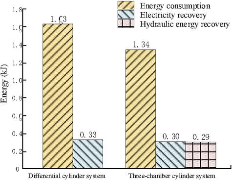
Figure 16 Comparison of system energy consumption.
In a working cycle, the actual energy consumption of the differential cylinder system is 1.63 kJ regardless of electric energy recovery. The energy consumption of the three-chamber cylinder system is about 1.34 kJ. However, the energy recovery of the accumulator B is 0.29 kJ, so the actual energy consumption of the three-chamber cylinder system is 1.05 kJ. If electric energy recovery is considered, the actual energy consumption of the differential cylinder system is 1.31 kJ, and that of the three-chamber cylinder system is 0.74 kJ. The proposed three-chamber cylinder system can save approximately 43.51% of energy.
Figure 17 compares the efficiency of the differential cylinder system and the three-chamber cylinder system.
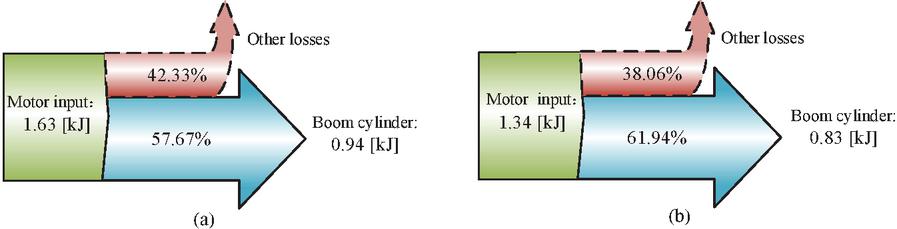
Figure 17 Comparison of boom system efficiency (a) differential cylinder; (b) three-chamber cylinder.
The servo motor input energies of the differential cylinder system and the three-chamber cylinder system are 1.63 kJ and 1.34 kJ, respectively, and the hydraulic cylinder consumed are 0.94 kJ and 0.83 kJ, respectively. The efficiency of the three-chamber cylinder system (61.94%) is about 4.27% higher than that of the differential cylinder system (57.67%), mainly due to the use of a special structure of the three-chamber hydraulic cylinder and accumulator B. In addition, the required flow rate is reduced under the same speed conditions because of smaller effective working area, when using three-chamber cylinder. To a certain extent, the system has added damping and reduced the speed oscillation further.
6 Conclusions
In order to boost the energy efficiency of the hydraulic boom, this paper proposes a novel energy-saving system, a variable-speed pump-controlled three-chamber cylinder using speed feed-forward LADRC control. The proposed system provides good position control performance while ensuring high energy recovery efficiency. The following main conclusions are derived from the analysis of the proposed system’s position tracking performance and energy consumption characteristics:
(1) The control system with the feed-forward LADRC algorithm can achieve a stable state smoothly. The position tracking error is controlled within 2.66% and has no overshoot to the position signal. Therefore, the control performance of the feed-forward LADRC is better than that of the PID, which can better meet the position control needs of the variable-speed pump-controlled system.
(2) Compared with the variable-speed pump-controlled differential cylinder system, when energy recovery is considered, the energy consumption during the boom operation is reduced by 43.51% with the proposed three-chamber cylinder system using feed-forward LADRC. Also, the peak power of the power source is reduced by 27.77%. Therefore, significant energy saving can be achieved with the proposed system.
Funding
This research was funded by Fuxiaquan National Independent Innovation Demonstration Zone High-End Flexible Intelligent Packaging Equipment Collaborative Innovation Platform Project (No. 2023-P-006), China; Fujian Province 2022 central government guiding local science and technology development projects (No. 2022L3014), Marine Research Special Fund Project of Fujian University of Technology (No. GY-Z23087).
Abbreviation
| ADRC | Active disturbance rejection control |
| LADRC | Linear active disturbance rejection control |
| PMSM | Permanent magnet synchronous motor |
| PID | Proportional-integral-derivative |
| FFC | Feedforward control |
| JCMAS | Japan Construction Mechanization Association |
| NLESO | Nonlinear expanding state observer |
| LESO | Linear expanding state observer |
| PD | Proportional-derivative |
| RMSE | Root mean square error |
References
[1] Quan Long. Current State, Problems and the Innovative Solution of Electro-hydraulic Technology of Pump Controlled Cylinder[J]. Chinese Journal of Mechanical Engineering, 2008, 44(11): 87–92.
[2] Lodewyks J, Zurbrugg P. Decentralized energy-saving hydraulic concepts for mobile working machines[C]/10th International Fluid Power Conference, Dresden, Germany, March 8–10, 2016(1):79–90.
[3] Kagoshima M, Komiyama M, Nanjo T, et al. Development of new hybrid excavator[J]. Kobelco Technology Review, 2007, 27(27):39–42.
[4] Altare G, Vacca A. Design Solution for Efficient and Compact Electro-hydraulic Actuators[J]. Procedia Engineering, 2015, 106:8–16.
[5] Schneider K, Liebherr P. Hybrid Power Booster: Energy Recovery and Increased Performance with Hybrid Drive System[C]. 7th AVL International Commercial Powertrain Conference: 2013. 59–64.
[6] Ho, Triet Hung, and K. K. Ahn. Design and control of a closed-loop hydraulic energy-regenerative system[J]. Automation in Construction. 2012(22): 444–458.
[7] Nezhadali V, Frank B, Eriksson L. Wheel loader operation-Optimal control compared to real drive experience [J]. Control Engineering Practice, 2016, 48: 1–9.
[8] Cetinkunt S, Pinsopon U, Chen C, et al. Positive flow control of closed-center electrohydraulic implement-by-wire systems for mobile equipment applications[J]. Mechatronics, 2004, 14(4): 403–420.
[9] Hippalgaonkar R, Ivantysynova M. Fuel savings of a mini-excavator through a hydraulic hybrid displacement-controlled system[C]//Proceedings of the 8th International Conference on Fluid Power (IFK). 2012:139–153.
[10] Tony Thomas, A. et al. Improved Position Tracking Performance of Electro Hydraulic Actuator Using PID and Sliding Mode Controller[J]. IETE Journal of Research, 2019(68): 1683–1695.
[11] Kim K Y, Jang D S, Cho Y L, et al. Development of Electro-Hydraulic Control Valve for Intelligent Excavator[C]. 2009 ICCAS-SICE, Fukuoka, Japan, 2009. 2212–2216.
[12] Krstiæ, Miroslav. On the applicability of PID control to nonlinear second-order systems[J]. National Science Review 2017 (4): 668–668.
[13] Patre P M, Mackunis W, Dupree K, et al. Modular Adaptive Control of Uncertain Euler–Lagrange Systems With Additive Disturbances[J]. IEEE Transactions on Automatic Control, 2011(1):56.
[14] Plestan F, Shtessel Y, Brégeault, Vincent, et al. Sliding mode control with gain adaptation – Application to an electropneumatic actuator[J]. Control Engineering Practice, 2013, 21(5):679–688.
[15] Rubaai A, Castro-Sitiriche M J, Ofoli A R. Design and Implementation of Parallel Fuzzy PID Controller for High-Performance Brushless Motor Drives: An Integrated Environment for Rapid Control Prototyping[J]. IEEE Transactions on Industry Applications, 2008, 44(4):1090–1098.
[16] Seung H C, Siegfried H. Robust motion control of a clamp-cylinder for energy-saving injection moulding machines[J]. Mathematics and Computers in Simulation. 2008(22): 2445–2453.
[17] Alleyne A, Hedrick J K. Nonlinear adaptive control of active suspensions[J]. Control Systems Technology, IEEE Transactions on. 1995, 3(1): 94–101.
[18] Le V A, Le H X and Nguyen L, et al. An efficient adaptive hierarchical sliding mode control strategy using neural networks for 3Doverhead cranes[J]. International Journal of Automation & Computing, 2019, 16(5):614–627.
[19] U Liping, Cai Liujin & Li Jian, et al. Control Strategy of Electro -hydraulic Position Servo System for Surface Milling Machine Based on Active Disturbance Rejection Control[J]. Computer Integrated Manufacturing Systems, 2018, 24 (11):122–130.
[20] Wu Hongtao. Self-interference control of permanent magnet synchronous motor based on feedforward compensation and motor parameter identification[D]. Hunan University of Technology, 2021.
[21] Chi Shiwei, Liu Huibo. ADRC Control of Permanent Magnet Synchronous Motor Based on the Feedforward Compensation[J]. Motor and control applications, 2023, 50(1):5.
[22] Han J.Q. From PID to active disturbance rejection control[J]. IEEE Transactions on Industrial Electronics, 2009, 56(3):900–906.
[23] Han Jingqing. Active Disturbance Rejection Control Technique[M]. Beijing: National Defense Industry Press, 2008.
[24] Xiao Yougang, Lu Hao and Yu Yi, et al. WADRC for anti-swing positioning of underactuated crane with one parameter tuning[J]. Journal of Central South University (Science and Technology), 2019, 50(11):2074–2711.
[25] Raul-Cristian Roman, Radu-Emil Precup and Emil M. Petriu. Hybrid data-driven fuzzy active disturbance rejection control for tower crane systems[J]. European Journal of Control, 2021, 58:373–387.
[26] Cao X, Wang Z and Zhang X. Precise locating control for a polar crane based on sliding mode active disturbance rejection control and quadratic programming algorithm[J]. Machines, 2021, 9(2):22.
[27] Gao Z Q. Scaling and bandwidth-parameterization based on control tuning[C]. //Proceedings of the American Control Conference. Denver, Colorado: IEEE, 2003: 4989–499.
[28] Agostini T, De Negri V, Minav T, et al. Effect of Energy Recovery on Efficiency in Electro-hydrostatic Closed System for Differential Actuator[J]. Actuators. MDPI, 2020, 9(1):12.
[29] Siwek M, Baranowski L, Panasiuk J, et al. Modeling and Simulation of Movement of Dispersed Group of Mobile Robots Using Simscape Multibody Software [C] // AIP Conference Proceedings. 2019, 2078: 020045-1–020045-5.
[30] Zhang Fengrong. Position and Speed Compound Control Method for Unidirectional Speed-variable Constant Pump-controlled Differential Cylinder[D]. Shanghai Jiaotong University, 2017.
[31] SlGuolei, Shen Yingqi and Wang Jialei, et al. Active Disturbance Rejection Control of Electro-hydraulic Position Servo System[J]. Chinese Hydraulics & Pneumatics, 2020, (12):14–21.
[32] Chen X, Li D, Gao Z, et al. Tuning method for second-order active disturbance rejection control[C]. 2011 30th Chinese Control Conference (CCC). IEEE, 2011:6322–6327.
Biographies

Shuzhong Zhang received the bachelor’s degree in mechanical engineering from Southwest Jiaotong University in 2003, the master’s degree in signal and information processing from Chendu University of Technology in 2006, and the philosophy of doctorate degree in mechanical engineering from Southwest Jiaotong University in 2011, respectively. He is currently working as a Professor at the Department of Mechanical Engineering, Fujian University of Technology, China. His research areas are fluid power control and energy saving. He has been serving as a reviewer for many highly-respected journals.

Borui Wang received a bachelor’s degree from the School of Mechanical Engineering of Xihua University in 2021. He currently is a master student at Fujian University of Technology, China. His current research areas are fluid power control and energy saving.

Tatiana Minav received a Doctor of Science degree from Lappeenranta University of Technology in 2011. She is currently working as an Associate Professor (tenure track) at Faculty of Engineering and Natural Sciences, ATME, Tampere University, Finland. She is an expert in electro-hydrostatic systems and actuators, cylinder’s sensorless position motion control, simulation, energy balance, and energy recovery systems in non-road mobile machinery. During her academic career, she worked and lead industrial projects funded by Business Finland (former Tekes) and by the Academy of Finland) related to the electrification of off-road machinery and its implements. She has been serving as a reviewer for many highly-respected journals.

Yiwen Tang received a master’s degree from Sichuan University in 2008. She currently is a technician at Fujian University of Technology, China. Her current research areas are fluid power transmission.

Yu Guo received a bachelor’s degree from the School of Mechanical Engineering of Heilongjiang University in 2021. He currently is a master student at Fujian University of Technology, China. His current research areas are fluid power control and energy saving.
International Journal of Fluid Power, Vol. 25_3, 349–374.
doi: 10.13052/ijfp1439-9776.2533
© 2024 River Publishers