Dynamic Response Analysis of the Main Plunger in A Two-stage On/Off Poppet Valve for the Digital Hydraulics Field
Essam Elsaed1, 2,* and Matti Linjama1
1Faculty of Engineering and Natural Sciences, Tampere University, Finland
2Faculty of Engineering Ain Shams University, Egypt
E-mail: essameldin.elsaed@tuni.fi; essam.elsaed1@gmail.com
*Corresponding Author
Received 30 November 2023; Accepted 26 June 2024
Abstract
The necessity for greater energy conservation in hydraulic machinery is highlighted by escalating fuel costs and heightened ecological awareness. Utilizing independent metering to enhance the energy utilization of hydraulic actuators is one effective strategy, yet the market is short on efficient reversible proportional valves that can perform this function. For handling modest flow rates up to 150 Liters per minute, the digital hydraulic method utilizing fast direct operated on/off solenoid valves shows promise; however, solutions for managing larger flows remain vague. This research explores the application of pilot-operated solenoid valves in digital hydraulic systems designed for substantial flow volumes. It establishes a model grounded in physical principles to examine how various factors influence the valve reaction speed. A unique valve design was established, derived from an existing valve but with a modified structure.
The findings indicate that the pressure difference, viscosity of the fluid and pilot plunger dynamics are crucial determinants of the valve response time. Incorporating a stroke limiter proves significant in harmonizing the response times across valves with varying flow rates, while the traditional methods of deploying serial orifices is deemed unsuitable. A glance from the results shows that at a P of 10 bar, the valve with an 8 mm attached serial orifice has an opening response of 65 ms, while the stroke limited valve achieves 40 ms. This significant advantage slightly narrows at higher pressures, stabilizing at 100 bar. During closing, the stroke limiter is remarkably 60% faster at 10bar, and both configurations settle at 40 ms at 200 bar.
Keywords: Digital hydraulics, multistage valves, on/off valves, high-flow valves, cartridge valves.
1 Introduction
The need for improving efficiency in valve controlled hydraulic systems is vital, given the advancements in competing technologies such as Electro Hydrostatic Actuation (EHA) and Electromechanical Actuation (EMA). Despite their advantages [1], challenges such as achieving high pressure and large flow simultaneously, at a compact size, realistic weight, and fast dynamic response, limit their applicability in certain contexts [2, 3]. In industrial and off-road machinery, two-stage proportional cartridge valves are useful when substantial flow rates and lightweight components are needed. A cartridge valve fundamentally consists of a plunger placed in the main block, while fluid pressure acts on the plunger on both sides, giving a hydrostatic equilibrium [4]. This paper is a post-conference (SICFP23) publication, further elaborating on the findings presented at [5].
Digital hydraulic technology, in which on/off valves are placed in parallel schemes with distinct flow rates, is still under investigation. According to several experiments, this technique outperformed conventional proportional valves at modest flow rates [6, 7]. Its flow capability could be increased by including two-stage on/off cartridge valves in the digital hydraulics library. However, for the valve to be accurately and efficiently functional, a well-predicted model and a fast-switching behavior are required.
For 2/2 two-stage cartridge valves to have a greater flow capacity and higher dynamic performance, they need a very sophisticated design. Depending on the kind of moving plungers (poppet or spool) these valves can be made. Poppet valves having less leakage, are less susceptible to contaminated particles, and are better suited for high flows than spool valves [8]. Two-stage poppet valves have two piloting options: external [9] and internal [10] (presented case study). On/off internally piloted valves present a simpler and more compact option compared to those with external pilot pressure systems. On the other side, achieving bidirectional functionality in internally piloted valves is a complex task. One valve that exemplifies this challenge and is currently under development is the EHPV by HUSCO International [11].
In the presented literature, several studies focus on the operating conditions and structural aspects of internally pilot-operated valves. For instance, the work of Muller and Fales [12] reveals that the dimensions of a valve inlet area can be critical, with smaller inlets contributing to slower closure times in a 2/2 metering poppet valve, as deduced through techniques such as root locus and Bode diagrams. Moreover, in 2014, Lei et al. [13] found that for pilot-operated valves used in water hydraulics, there is a direct correlation between inlet pressure and the speed of the valve opening and closing response time. Additionally, the slowest valve responses have been observed under conditions of low-pressure drops and minimal openings [14].
Other studies emphasize the dynamics of these valves. Zardin et al. [15] explored the design of a two-stage electrohydraulic On/Off cartridge valve and found that its response time is significantly influenced by the pilot stage dynamics and the fluid-dynamic behavior of the main poppet, with simulations conducted via CFD. In more recent research, Choi et al. [16] focused on the dynamic behavior of a driving unit in a 2/2 pilot-operated solenoid valve, specifically seeking to quantify the system coefficients such as the damping coefficient. Their analysis revealed that the valve motion is characterized by a two-phase sequence involving the pilot and the main plungers. Further study [17] has indicated that pilot flows play a dual role in controlling and contributing to the overall flow in valves with similar configurations.
Increasing the flow capacity of Digital Flow Control Units (DFCUs) presents numerous possibilities for expanding its applications [18]. For instance, high flow rate multistage has been integrated [19]. The 2/2 pilot operated solenoid valve GS0205, capable of 19LPM at a 5-bar pressure difference, was utilized to boost the output of two digital flow control units (DFCUs). The researchers have highlighted deficiencies in the response time of pilot valves, which can negatively affect the overall performance of the hydraulic system. Moreover, the flow capacity measurements were approximate, as viscosity was not factored into the valve model. Such an unpredictable valve response can induce pressure spikes during state transitions, notably in binary-coded DFCUs [20]. The following year [21], this valve was also used in systems with four DFCUs. In a related development, Aalto University Lantela and Pietola [22] designed a DFCU utilizing 32 pilot operated miniature on/off valves (30LPM at 5 bar). Notably, the most advanced DFCU using solely direct operated valves (WS22GDA-10) in a digital valve system presented a relatively low flowrate of 115LPM at 5 bar was recently engineered by Ketonen et al. [23].
Interestingly, digital hydraulic researchers seldom use pilot-operated valves due to their slower response times, despite the trade-off in flow rate. This presents a research gap: finding a fast pilot valve capable of handling high flow rates. Previous aforementioned literature by scholars outside the field of digital hydraulics offers minimal guidance on designing 2/2 on/off internally pilot-operated valves for DFCUs. Common research simplifications include constant control volume assumptions, linearized models, and the omission of temperature effects. Traditionally, serial orifices at the valve outlet regulate flow discretely in DFCUs, but this leads to prolonged response times with pilot-operated valves. Therefore, it has been largely avoided by digital hydraulics researchers. A novel solution proposes limiting the main plunger stroke to reduce flow rates while potentially improving overall performance.
Stroke limiters on the market are rare. Bucher Hydraulics has released a 2/2 logic cartridge valve, model WL22SD size 10 (Q up to 150LPM), featuring an “adjuster” in their special valve library, yet this can only limit the main valve of a controllable pilot pressure valve assembly [24]. Sun Hydraulics offers stroke adjustment options in their 2-way proportional throttle models FTDAL and FTEAL (Q up to 110LPM); these, however, are spool valves [25]. Bosch Rexroth has a “pressure limitation stroke” in their 2-way flow control valve Type 2FRM series (Q up to 160LPM), yet these aren’t pilot-operated valves [26]. Rexroth also provides high-flow 2-way cartridge logic valves LCT where stroke limitation is possible through “Stroke limitation, throttle function” with set control covers [27]. Similarly, Hydac [28] has valves that match in performance but, like Rexroth, are externally piloted – different from the internally piloted valves discussed in this paper, where stroke adjustment is limited to manufacturer-prescribed values.
Based on the above survey, the stroke limiter technique suitable for our design can be divided into three scenarios, as shown in Figure 1. It is important to note that these methodologies are commonly used for external pilot cartridge valves, not internal pilot valves, which creates an innovative opportunity to explore their implementation in internally piloted valves. However, the authors have also studied the drawbacks before implementing this idea. The adjustable screwed stroke limiter faces issues such as mechanical wear over time, increased manufacturing and assembly complexity, and higher costs. The fixed-size cover limiter lacks flexibility since it cannot be adjusted, requiring replacement for different stroke limits and complicating logistics by needing an inventory of various sizes. The inserted bushes option is challenging due to time-consuming installation and removal processes, potential wear, and difficulties in achieving precise stroke limits.
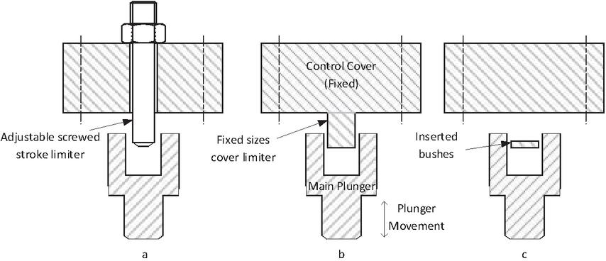
Figure 1 Stroke Limiter Mechanisms for a 2-Way Pilot Operated Valve: (a) Adjustable screwed stroke limiter. (b) Fixed-size cover limiter. (c) Inserted bushes limiter.
To sum up, this article addresses two key points in the field of digital hydraulics: the significant simplifications often made in external research areas and the negative impact of adding a serial orifice to pilot-operated valves. To tackle these issues, the authors introduce a novel internally piloted, modified stroke-limited 2/2 on/off poppet cartridge valve, which is not yet available on the market according to the authors’ knowledge. Additionally, provides a basis for analyzing the main factors affecting these valves, laying the groundwork for future accurate modeling.
2 Mathematical Modelling
The chapter is structured into three sections. Initially, it investigates the analysis of force and flow, paired with an overview of valve operation. The second section provides an in-depth discussion of valve operation dynamics and the underlying governing equations. Finally, the chapter concludes with an examination of the implementation of the stroke limiter and the detailed governing equations for serial orifices.
2.1 Structure and Operation of the Multistage Solenoid Valve
Valve specification, internal components, and force analysis
Figure 2 presents a simplified schematic of the valve structure. The focus of this study is on the Parker 2-way cartridge valve, Series DSH161, which features a two-stage design [29]. The valve was remodeled using 3D software based on general dimensions from the manufacturer. This On/Off valve utilizes a poppet plunger in both the pilot and main stages, offering a flow capacity of 150LPM and a maximum inlet pressure tolerance of 350bar. The valve dimensions correspond to the SAE16/NG12 size. Notably, the pilot pressure line originates from the inlet port. As a result, fluid is permitted to flow from the out-port to the in-port when the pressure at the out-port attains a certain threshold. Conversely, flow from in-port to out-port is restricted unless the pilot valve (plunger) receives an activation signal [4]. The operational stages of the valve are detailed in the subsequent sections:
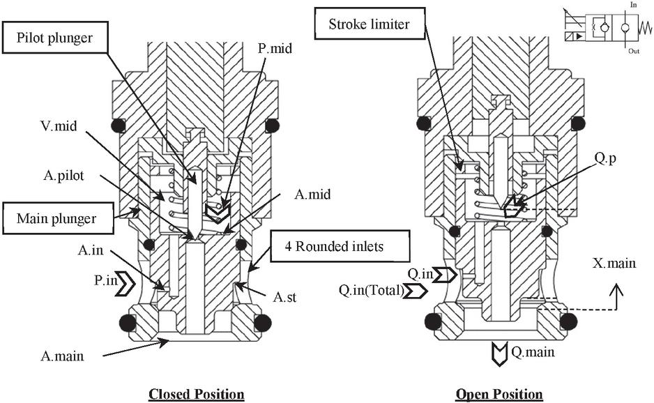
Figure 2 Operational diagram for the 2-way on/off two-stage valve modified from [29].
In the default state, the pilot plunger and the main plunger are in the closed position . The system is set with high pressure supplied to the four main inlet ports, and low pressure connected to the outlet port. The pilot orifice, denoted as , remains closed, while the high-pressure fluid from from the inlet orifice groove fills the control volume , keeping the main poppet closed by applying pressure. Simultaneously, the main plunger is under the influence of the spring force () and the viscous damping force ().
When the pilot plunger is energized, it triggers the opposite response by opening the pilot circuit. This action causes the pressure in the middle chamber () to drop, resulting in a differential pressure across the main plunger that overcomes the combined forces of the spring, viscous damping, and the pressure in the mid-chamber. Consequently, the main plunger moves towards the open position, causing the main poppet area () to gradually open. This leads to a decrease in the pressure level within the mid-chamber until it reaches a point of saturation [13], at which pressure equalization takes place.
Table 1 Parameter values for Figure 2
| mid-chamber diameter | pilot opening diameter | mid-chamber length |
| main plunger diameter | inlet orifice diameter | main plunger length |
| pilot plunger maximum stroke | pilot plunger half angle | main poppet mass |
| main plunger maximum stroke | main plunger half angle | coefficient of discharge for orifice, main and pilot plungers |
The hydraulic valve in hand features several components with distinct dimensions and properties as shown through Table 1. The discharge coefficients, , used for the orifice (will be presented in Figure 5) and both the main and pilot plungers, , and , are consistently 0.61 [8].
Flow diagram for the studied case
Referring to Figure 2, the incoming flow, , moves through the inlet groove area, , influenced by a variable discharge coefficient, into the middle volume, . The pilot valve manages a smaller flow, , with a consistent discharge coefficient, , within the pilot circuit (assuming the valve has a thin sharp-edge orifice, hence the temperature effect is disregarded [8]). This flow creates a pressure differential across the main poppet mass, , causing it to rise to its maximum position, . Consequently, the main outflow, , assumed to have a steady discharge coefficient, , passes through . When a serial orifice, , is integrated, a discrete outflow, , at a constant discharge coefficient, , is obtained (Figure 5). For clarity, it should be emphasized that scenarios do not exist where the orifice is attached simultaneously with the limitation of the main plunger stroke.
Main & pilot poppet areas
The pilot plunger controllable area is simplified in the model as shown [8]
| (1) |
Likewise, the main plunger area is formulated as:
| (2) |
The pilot opening area, , changes according to the displacement differential between the pilot and main plungers. It’s also noted that this displacement difference remains small so that when the main plunger reaches its maximum opening, it marginally reduces the effective area of the pilot plunger due to the closeness between them.
In addition, the main plunger may achieve an equilibrium position slightly more than 3 mm given an adequate pressure difference, , but in the model, this is limited to a maximum displacement, mm, imposed by a mathematical saturation [30]. The base of the main valve plunger has been designed with an almost rectangular main valve port, , to maintain a linear flow at small openings [31].
Flow restrictions coefficients of discharge
At the inlet orifice, with bar to 350 bar)@ mm/s, the recorded inlet flow rates, , range from (1 to 7)LPM (20 to 140) m/s @ mm. Consequently, the corresponding Reynolds number, 500 to 3500. To compute the discharge coefficient, , formulas from sections 3.64 to 3.67 in the cited book [32] were referenced. The takes into account several parameters: the main inlet diameter (with four rounded circular inlets at 8.5 mm each), fluid viscosity, fluid density, orifice thickness (2 mm), orifice diameter , and the pressure drop (). A graphical illustration of this equation applied to the inlet orifice can be seen in [5].
The oil temperature is kept constant at C as per the manufacturer specification for evaluating other flow restriction devices. The corresponding values for properties such as density, bulk modulus, and particularly viscosity was derived at this temperature. These properties are assumed constant except when examining the temperature effect on the valve response (Section 3.1.1).
2.2 Dynamic Modelling of the Two-stage Valve
2.2.1 Valve dynamics
This section begins with formulas derived from the dynamic modeling of the valve, leaving out the serial orifice flow equation and the implementation of the stroke limiter. The overall valve model can be segmented into two main parts: firstly, a simplified input command for the pilot poppet, and secondly, the spring-mass-damper system combined with the flow equations for the main poppet.
1. Pilot Plunger: The input signal to the pilot unit, denoted as , incorporates a fixed delay of 5 ms, and the output adheres to a defined response rate with an opening time and a closing time of ms/ ms respectively. Typically, a high-performance pilot plunger will improve the rate at which the pilot control chamber, , is filled or emptied, which consequently can reduce the response time of the main valve.
Moreover, the displacement of the pilot plunger, , is constrained by the movement of the main plunger, , as detailed in Equation (3). This interaction is only relevant during the valve closing phase. It can be understood to mean that if the non-filtered movement of the pilot plunger, closes faster than the main plunger, it will then follow the path of the slower-moving main plunger [33].
| (3) |
2. Main plunger: Equation of motion Assuming that upward motion (the direction that opens the valve) is the positive direction (, the equation for the forces acting on the main poppet in its motion can be written as:
| (4) |
The forces on the main poppet, ignoring flow forces as hydraulic pressure forces are significantly larger [14, 33], are expressed as:
| (5) |
A free body diagram (Figure 3) is provided below to facilitate a clearer understanding of the previous equations.
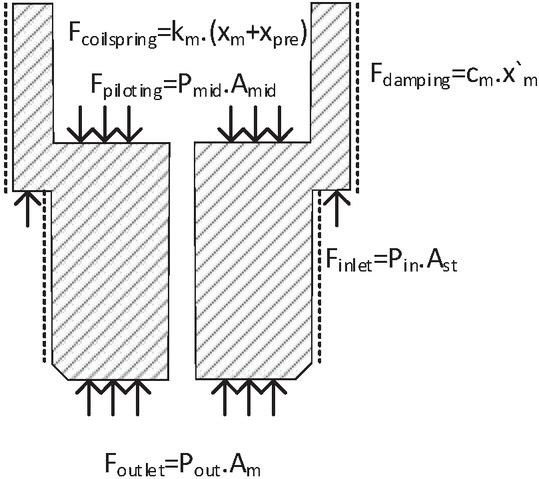
Figure 3 Main plunger free body diagram.
A soft compression spring is installed on the main poppet within the control chamber to ensure the main valve remains closed when no fluid forces are present. The spring constant coefficient , defined as is 330 N/m, where , assuming mm, GPa and . Additionally, is considered to be 2 mm. Generally, a higher value will slow down the valve opening response. The damping coefficient, , can be determined using the formula:
| (6) |
Where the radial clearance, is 10 micrometers, and the length of the main plunger, , is 25 mm. This gives a to 1.2@ Ns/m [34]. For simplicity, other damping factors such as oil seal friction or damping due to oil flow restriction through the pilot area were omitted [35]. In scenarios where values are small, oscillations might occur, particularly at the beginning and end of the stroke. The values for and are in line with those reported by Choi et al. in their study of a two-stage valve [16].
Compressibility & Flow equations
The equation for the rate of change in pressure in the mid-volume, , is represented by Equation (9) [36]. The effect of on is considered negligible due to the small size of area and displacement , especially when compared to the main poppet. In terms of the control volume, as the main plunger moves downward (closing), the volume increases, and it decreases when the plunger moves upward (opening). Once the main plunger reaches the closed position, , the initial volume of the control chamber, . Therefore, the mid chamber volume [37, 38] is modeled by.
| (7) |
and accordingly, the rate of change of mid chamber volume calculated as.
| (8) |
It is crucial to note that a larger control chamber may lead to an increased response time, although it can help reduce overshoots, as indicated in the references [33, 39].
| (9) |
The fluid flow through flow restrictions was modeled based on the principle that it is proportional to the square root of the pressure difference across the restriction. This assumption leads to the relationships as outlined in the equations numbered (10), (11), (12), (13), and (14): [40].
| (10) | |
| (11) | |
| (12) | |
| (14) |
Where is , is the total pilot flow including the flow due to the main plunger displacement, and is the total flow including both the main outlet and total pilot flows. The derivations indicate that the movement of the main poppet is directly and proportionally influenced by the movement of the pilot valve, as referenced in [14, 41].
2.3 Stroke Limiter and Orifice Implementation
Stroke limiting
Mathematically, the stroke limiter in the valve is an adjustable component that physically restricts the movement range of the main plunger. It is typically located within the valve housing above the main plunger control volume and features an internal thread (Figure 4). This adjustment directly controls the extent of the valve opening, thereby modulating the flow rate. In the simulation, this parameter is represented as , and modifying it simulates the physical adjustment of the stroke limiter in the actual valve setup.
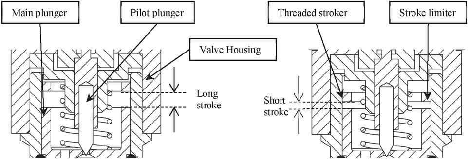
Figure 4 Magnified diagram for stroke limiting methodology.
Mechanically, the stroke limiter is physically adjusted using an external screw mechanism. This screw, accessible from the valve exterior, allows precise control over the main plunger maximum displacement. By turning the screw, the position of the internal limiter can be incrementally adjusted, thereby setting a new maximum stroke length for the plunger. This allows for precise control over the valve performance in various operating condition. Additionally, the stroke limiter directly restricts the movement range of the main plunger, which in turn limits the maximum valve opening. This can reduce the maximum achievable flow rate through the valve. However, this feature is beneficial when the valve is implemented in a DFCU, as it minimizes the flow rate to provides discrete values, traditionally achieved by adding orifices.
Orifice
The change in pressure in the volume between the serial orifice and the valve outlet (Figure 5) is given by Equation (15); in this case, the rate of change of volume . To model different scenarios, the orifice area can be adjusted as required.
| (15) |
The flow rate associated with this configuration is described by Equation (16). It should be noted that having a constant volume ) between the serial orifice and the outlet port results in additional pressure losses in the model, even when the orifice diameter , as shown in Equation (15).
| (16) |
Another important consideration is that if a serial orifice is installed, the term in Equations (11) and (12) should be replaced with .
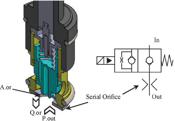
Figure 5 Tractional attached orifice to the 2/2 pilot operated valve (no stroke limiter) modified from [29].
3 Results
The results section is organized into two distinct parts: it begins with a progress through the optimization of valve performance and concludes with a comparative feasibility study between the use of the serial orifice technique and the stroke limiter. The valve performance has been validated, showing a close match between the modeled and datasheet pressure loss, as previously mentioned in the authors’ earlier publication [5].
3.1 Valve Sensitivity Analysis
The effect of each parameter on valve response is exhibited through the detailed analysis of the physical structure of the cartridge valve. For clarity, both the pilot ideal command and the normalized, non-filtered pilot plunger position () appeared in the graphs (Equation (1)).
3.1.1 Pressure & Temperature Effect
Analysis of Figure 6 (a1, a2) reveals that an increase in inlet pressure leads to rapid valve responses in both opening () and closing () phases. During closure ), enhanced fluid flow into the mid chamber results in a downward force concisely expressed as . In contrast, during the opening phase , an elevated inlet pressure, when combined with a constant outlet pressure, allows more fluid to exit via , summarized as . This relationship implies that . However, the outlet pressure () demonstrates a contrary pattern, applicable primarily to valves with constant pilot pressure. According to Jun et al. [42], in valves with controllable (external) pilot pressure, influence on response time is minimal, as the rate of filling or emptying of is independently controlled.
It is important to emphasize that when the main plunger response time reaches the pilot valve response time limit, the influence of pressure becomes minimal. Essentially, the main plunger speed is limited by the pilot plunger speed (Equation (3)).
Regarding the impact of oil temperature () on valve response time, as shown in Figure 6(b), the model indicates that only is affected by temperature changes. This causes an increase in flow into at higher temperatures, while remains unchanged (). Consequently, increases during closure but does not decrease as rapidly during opening. The reason why response times () at 40C and 60C are similar is attributed to the saturation of at 0.8 as disused in detail by the authors previously in [5]. Furthermore, Figure 6(b) suggests that the influence of temperature is nearly negligible due to the relatively high-pressure values. Therefore, since the valve performance improves at high P, utilizing a low system pressure will be an effective approach to clearly demonstrate the impact of other parameters on valve response in the subsequent figures.
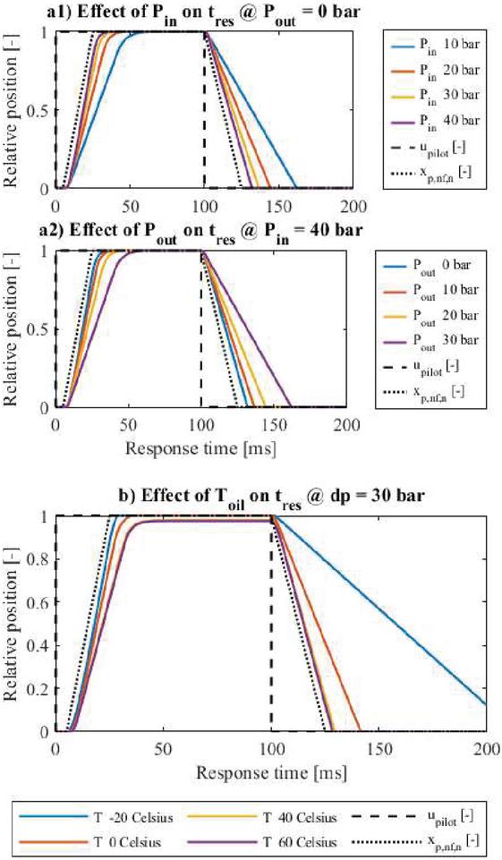
Figure 6 (a1, a2) Impact of inlet and outlet pressures on valve response time. (b) Influence of temperature variations on valve response time.
3.1.2 Valve inlet & pilot diameter selection
Figure 7(a) demonstrating the impact of inlet orifice area on valve response time. A decrease in leads to a faster drop in mid chamber pressure due to reduced high-pressure oil flow into , aligning with Equations (9) and (10), resulting in a shorter opening response time for the main valve. Conversely, the closing velocity of the main plunger is reduced due to decreased high-pressure oil supplementation, as experimentally confirmed by Xu et al. [36]. Designing the inlet orifice for optimal opening and closing times requires a balance, with an alternative approach involving a variable inlet orifice as outlined in [12].
Figure 7(b) illustrating a different pattern. Here, plays a key role in mid-chamber depressurization, a relatively large enhances opening response time as decreases swiftly, a finding confirmed in [15]. However, the impact of a large is negligible during closure in realistic diameters, as the pilot poppet closes faster than the main poppet under simulated conditions. As a result, it closes the entire pilot area in a relatively short time. Subsequently, both components move simultaneously as a single unit, allowing the main plunger to close under the influence of the pressure forces, which remain constant regardless of the value of . In simple words, the effect of the pilot orifice area becomes negligible when it is closed.
An extreme case arises with a large and small , potentially causing the main plunger to stabilize before full displacement during opening (). It’s preferable to have larger than this allows for a slight movement in the pilot poppet to provide an exit orifice much larger than the inlet orifice, accordingly a significant pressure drop in the control volume, facilitating a rapid upward movement of the main plunger, as depicted in Figure 7.
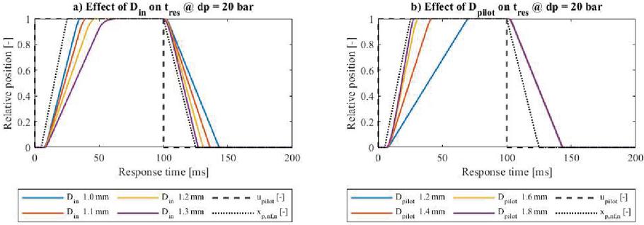
Figure 7 Effect of inlet orifice on valve response time (a). Effect of pilot orifice on valve response time (b).
3.1.3 Pilot valve response time
In the evaluation of hydraulic valve performance, Figure 8(a) offers insights into how variations in pilot plunger stroke influence the main plunger reaction time under a consistent differential pressure of 5 bars. Notably, a reduction in pilot plunger stroke correlates with an improvement in the main plunger response time. This inverse relationship also implies a decrease in flow rate; for instance, a pilot stroke of 3.5 mm yields a flow rate of 125 LPM, whereas a stroke of 1 mm results in a flow rate of 27 LPM.
The secondary graph in Figure 8(b) explains the impact of the pilot plunger response time, or its speed, on the main plunger performance, maintaining a constant flow rate of . Initially, as the speed of the pilot plunger decreases, there is a significant reduction in the main plunger response time. However, as the pilot plunger speed continues to go up further it results in a reduced rate of decrease in response time for the main plunger.
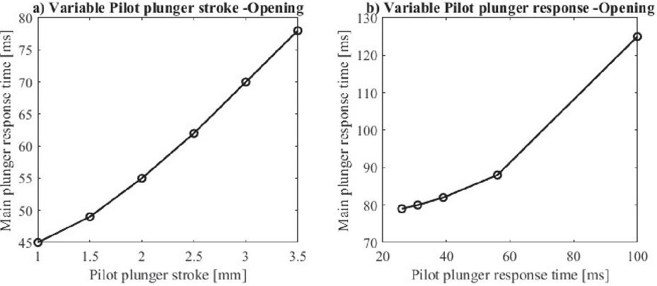
Figure 8 Response time at variable pilot plunger stroke (a), and at variable pilot plunger response time (b).
3.2 Stroke Limiter and Serial Orifice Performance Comparison
In Figure 9, it’s observed that as the input pressure () increases, the performance of the valve improves with both the serial orifice and the stroke limiter during its opening and closing phases. Furthermore, limiting the stroke from 1.5 mm to 0.75 mm reduces the time the valve takes to reach its equilibrium position during these phases. Specifically, when closing, the valve starting from a 1.5 mm stroke takes longer to close compared to a stroke limiter set at 0.75 mm. Additionally, the valve fails to fully close if the cycle of pilot pressure is too short and the pressure differential (P) is insufficient. Conversely, during opening, the valve outlet area increases linearly, meaning even a minor opening (a fraction of ) leads to a significant flow rate.
Notably, nearly 90% of the maximum flow is achievable with a valve stroke close to 2 mm at orifice diameter ( mm) and an input pressure of 350 bar. It is crucial to note that, when using a serial orifice in digital hydraulics, there are challenges in achieving rapid on/off switching.
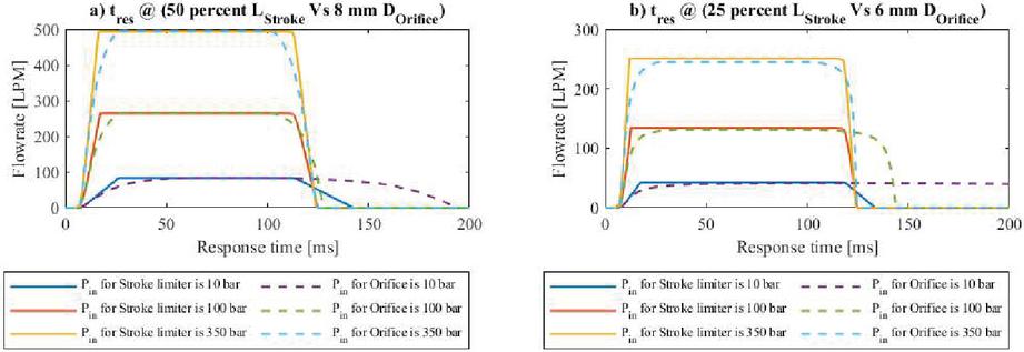
Figure 9 Response time at 50% Stroke & equivalent Orifice (a). At 25% Stroke & equivalent Orifice (b).
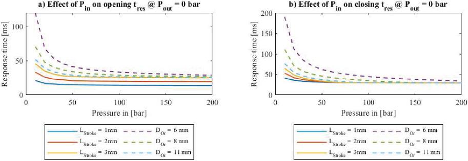
Figure 10 Response time comparison during opening (a). Response time comparison during closing (b).
Figure 10 provides a comprehensive overview of the system, highlighting the superior performance of the stroke limiter in enabling the main plunger to reach its final position ( mm) under various operating conditions. The shortest response times were observed with a stroke limiter setting of mm at an input pressure of 200 bar, which reached the same values of pilot plunger response times. Notably, the main plunger speed at full stroke exceeded the specified datasheet values, due to the unreported working conditions under which those values were measured. Additionally, at higher pressure values, the closing time () tends to be similar across all cases because: (I) The area of the plunger opening () decreases rapidly, and (II) The pressure differential (P) across the orifice becomes negligible relative to the input pressure (). The data collection started from an input pressure of bar because at lower pressures, the orifice response time is excessively long, obscuring the clarity of the results. Moreover, fitting very small orifices to a large valve is not advisable in practical applications.
It is noted that for achieving discrete flow rates the valve closing and opening time is directly proportional to the orifice size attached to the valve. Conversely, the valve closing and opening time is inversely proportional to the stroke length when using the stroke limiter (More details are provided in [5]). The conclusion drawn is both remarkable and intriguing.
A deeper insight into the valve performance is presented in Figure 11 illustrating that the stroke limiter exhibits a linear flow rate capacity based on the selection modeling methodology. Further explanation reveals that with an attached orifice, there are two restricted areas: the orifice and the plunger opening. However, with the stroke limiter implementation, only the plunger opening area contributes to flow control.
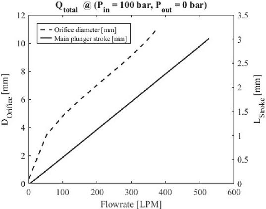
Figure 11 Effect of stroke limiter and attached serial orifice on valve flowrate.
4 Conclusion
An in-depth study was conducted on a 2/2 on/off poppet valve, specifically examining an internally piloted two-stage valve design. In this type of valve, the main poppet displacement is dynamically linked to the pilot valve operation, ensuring the valve flow area adjusts in response to the control signal. A comprehensive mathematical model was developed to analyze the impact of various design parameters. Furthermore, a novel stroke limiter mechanism was proposed with the aim of enhancing the valve response time while achieving a more compact design compared to serial orifices in digital hydraulic systems.
The findings indicate that the valve responsiveness diminishes with small pressure differentials, a situation further affected by temperature variations. The valve equipped with a stroke limiter exhibited quicker switching capabilities compared to a valve using a serial orifice at equivalent flow rates within digital hydraulic applications. Moreover, integrating multiple two-stage valves with stroke limiters has the potential to produce high-capacity digital flow control units (DFCUs).
Despite these advancements, certain aspects were simplified or overlooked in the model, including leakage, flow forces, constant spring stiffness, a simplified damping coefficient, and a stable supply pressure assumption.
Future Works
To validate the results by confirming that the stroke limiter responds faster as the stroke is decreased. In contrast, adding the corresponding orifice for the same flow rate shows that response time increases with the orifice size increases. Additionally, the 2/2 internally pilot valve with a stroke limiter is generally faster than with the attached serial orifice under the same operating conditions for both opening and closing.
Acknowledgements
This work was supported partially by the Ministry of Education in Finland, represented in Tampere university Automation Technology and Mechanical Engineering unit (ATME), specifically within the Innovative Hydraulics and Automation (IHA) Lab. And partially by the Egyptian Cultural Affairs and Missions.
References
[1] W. Lee, S. Li, D. Han, B. Sarlioglu, T. A. Minav, and M. Pietola, “A review of integrated motor drive and wide-bandgap power electronics for high-performance electro-hydrostatic actuators,” IEEE transactions on transportation electrification, vol. 4, no. 3, pp. 684–693, 2018.
[2] T. Guo, X. Han, T. Minav, and Y. Fu, “A preliminary design method of high-power electro-hydrostatic actuators considering design robustness,” in Actuators, MDPI, 2022, p. 308.
[3] D. Padovani, S. Ketelsen, D. Hagen, and L. Schmidt, “A self-contained electro-hydraulic cylinder with passive load-holding capability,” Energies, vol. 12, no. 2, p. 292, 2019.
[4] J. M. Bergada, Fluid power, mathematical design of several components. Nova Science Publishers, Incorporated, 2014.
[5] E. Elsaed and M. Linjama, “Modeling and Performance Analysis of a Two-stage On/Off Poppet Valve for Digital Hydraulics,” in SICFP23, Tampere, Finland, Jun. 2023.
[6] M. Huova, M. Linjama, and K. Huhtala, “Energy efficiency of digital hydraulic valve control systems,” SAE Technical Paper, 0148–7191, 2013.
[7] E. Elsaed, M. Abdelaziz, and N. A. Mahmoud, “Investigation of a digital valve system efficiency for metering-in speed control using MATLAB/Simulink,” presented at the International conference on hydraulics and pneumatics-23rd edition (HERVEX), 2017, pp. 120–129.
[8] N. D. Manring and R. C. Fales, Hydraulic control systems. John Wiley & Sons, 2019.
[9] A. H. Hansen, H. C. Pedersen, and T. O. Andersen, “Design of a multi-poppet on-off valve for wave energy converters,” presented at the 2013 IEEE International Conference on Mechatronics and Automation, IEEE, 2013, pp. 651–656.
[10] T. Lantela, “Miniature Digital Hydraulic Valve System-Pilot operated design with fast response and high flow capacity,” 2018.
[11] L. F. Jurado, “Husco EHPV’s,” Husco.com. Accessed: May 20, 2024. [Online]. Available: https://husco.com/husco-social/husco-ehpv-line-at-bauma-china/.
[12] M. T. Muller and R. C. Fales, “Design and analysis of a two-stage poppet valve for flow control,” International Journal of Fluid Power, vol. 9, no. 1, pp. 17–26, 2008.
[13] L. Lei, Z. Desheng, and Z. Jiyun, “Design and Research for the Water Low-pressure Large-flow Pilot-operated Solenoid Valve,” Strojniski Vestnik/Journal of Mechanical Engineering, vol. 60, no. 10, 2014.
[14] W. Liu, J. H. Wei, and B. Hu, “Analysis and Optimization of a Hydraulic-Feedback Proportional Throttlecartridge Valve,” presented at the Applied Mechanics and Materials, Trans Tech Publ, 2014, pp. 162–170.
[15] B. Zardin, M. Borghi, G. Cillo, C. A. Rinaldini, and E. Mattarelli, “Design of two-stage On/Off cartridge valves for mobile applications,” Energy Procedia, vol. 126, pp. 1123–1130, 2017.
[16] J. Choi, J. H. Ahn, and H. Y. Kim, “Modeling the dynamic behavior of a pilot-operated solenoid valve for an ultra-high pressure vessel,” Applied Sciences, vol. 11, no. 5, p. 2329, 2021.
[17] R. Zhang, A. G. Alleyne, and E. A. Prasetiawan, “Performance limitations of a class of two-stage electro-hydraulic flow valves,” International Journal of Fluid Power, vol. 3, no. 1, pp. 47–53, 2002.
[18] E. Elsaed, M. Abdelaziz, and N. A. Mahmoud, “Using a Neural Network to Minimize Pressure Spikes for Binary-coded Digital Flow Control Units,” International Journal of Fluid Power, pp. 323–352, 2019.
[19] E. Elsaed and M. Linjama, “A Review of Pilot-operated Hydraulic Valves–Development, Challenges, and a Comparative Study,” International Journal of Fluid Power, pp. 683–724, 2023.
[20] M. Linjama and M. Vilenius, “Digital hydraulic control of a mobile machine joint actuator mockup,” Power Transmission and Motion Control: PTMC, 2004.
[21] M. Linjama and M. Vilenius, “Energy-efficient motion control of a digital hydraulic joint actuator,” presented at the Proceedings of the JFPS International Symposium on Fluid Power, The Japan Fluid Power System Society, 2005, pp. 640–645.
[22] T. Lantela and M. Pietola, “High-flow rate miniature digital valve system,” International Journal of Fluid Power, vol. 18, no. 3, pp. 188–195, 2017.
[23] M. Ketonen and M. Linjama, “High flowrate digital hydraulic valve system,” presented at the The Ninth Workshop on Digital Fluid Power, 2017, pp. 7–8.
[24] B. Hydraulics, “Cartridge Valves Catalogue 2022/Special Directional Valves.”
[25] S. Hydraulics, “Stroke adjustment (L control).”
[26] B. Rexroth, “2-way flow control valve.”
[27] Bosch Rexroth, “2-way cartridge valves, pressure and directional functionsType LCT (cartridge valves); type LFT (control cover).” [Online]. Available: https://www.boschrexroth.com/en/us/media-details/d8056003-5aa7-427b-975c-bc29aa385b76.
[28] Hydac, “2-way Cartridge valves L-CEE and Control cover.” [Online]. Available: https://www.hydac-na.com/wp-content/uploads/Industrial\%20Valves.pdf.
[29] Parker Hannifin Corporation, “Technical Information: Poppet Type, 2-Way Valve Series DSH161.”
[30] A. Akers, M. Gassman, and R. Smith, Hydraulic power system analysis. CRC press, 2006.
[31] J. Yao, Y. Yin, Z. Dong, and Y. He, “Design of a 70 MPa Two-Way Proportional Cartridge Valve for Large-Size Hydraulic Forging Press,” JOURNAL OF BEIJING INSTITUTE OF TECHNOLOGY, vol. 29, no. 2, pp. 260–272, 2020.
[32] M. Jelali and A. Kroll, Hydraulic servo-systems: modelling, identification and control. Springer Science & Business Media, 2002.
[33] B. Winkler, A. Ploeckinger, and R. Scheidl, “A novel piloted fast switching multi poppet valve,” International journal of fluid power, vol. 11, no. 3, pp. 7–14, 2010.
[34] H. E. Merritt, “Hydraulic control systems, 1967,” J. Wiley.
[35] S. André, “Optimization of Valve Damping.” 2013.
[36] B. Xu, R. Ding, J. Zhang, and Q. Su, “Modeling and dynamic characteristics analysis on a three-stage fast-response and large-flow directional valve,” Energy conversion and management, vol. 79, pp. 187–199, 2014.
[37] M. Linjama, “Digital Hydraulics – MEC-E5004 Fluid power systems, lectures slides”.
[38] H. AbdelMeguid, P. Skworcow, and B. Ulanicki, “Mathematical modelling of a hydraulic controller for PRV flow modulation,” Journal of Hydroinformatics, vol. 13, no. 3, pp. 374–389, 2011.
[39] M. Han, Y. Liu, H. Tan, and D. Wu, “Mathematical Modelling and Multi-Objective Optimization Design of a Large Flow Water Hydraulic Proportional Cartridge Valve,” presented at the Fluid Power Systems Technology, American Society of Mechanical Engineers, 2017, p. V001T01A021.
[40] B. V. Hubballi and V. B. Sondur, “Modeling and simulation of conical poppet type relief valve with damping spool,” Hidraulica, no. 1, p. 13, 2016.
[41] Q. Long, X. Xiaoqing, Y. Zheng, and Z. Xiaojun, “A new kind of pilot controlled proportional direction valve with internal flow feedback,” Chinese journal of mechanical engineering, vol. 23, no. 1, pp. 60–65, 2010.
[42] T. Jun, “A pilot type of switch on/off valve for DFCU,” A: A, vol. 1, no. 2, p. 3.
Biographies

Essam Elsaed Is a researcher at the Automation Technology and Mechanical Engineering Unit, Tampere university. Finland.
https://orcid.org/0000-0003-3133-4655

Matti Linjama obtained a D Tech degree at Tampere University of Technology, Finland, in 1998. Currently, he is an adjunct professor at the Automation Technology and Mechanical Engineering Unit, Tampere University. He started the study of digital hydraulics in 2000 and has focused on the topic since then. Currently, he is a leader of the digital hydraulics research group, and his professional interests include the study of hydraulic systems with high performance and energy efficiency.
https://orcid.org/0000-0002-4861-5624
International Journal of Fluid Power, Vol. 25_3, 325–348.
doi: 10.13052/ijfp1439-9776.2532
© 2024 River Publishers