A Comprehensive Study of Energy-Saving Strategies Through Combined Throttling
Christian Reese Jimenez*, Olivier Reinertz and Katharina Schmitz
Institute for Fluid Power Drives and Systems (ifas), RWTH Aachen University, Campus-Boulevard 30, D-52074 Aachen, Germany
E-mail: christian.reese@ifas.rwth-aachen.de
*Corresponding Author
Received 26 January 2024; Accepted 13 March 2024; Publication XX XXXXXX XXXX
Abstract
In the field of pneumatic automation, downstream throttled pneumatic drives are widely adopted for motion tasks, valued for their cost-effectiveness, durability, and high-power density. However, this switching scheme is often regarded as being inefficient. Consequently, many researchers have focused on developing more efficient control strategies. In this paper a novel combined throttling scheme aimed at reducing air consumption is investigated. The paper offers a comprehensive overview of the design methodology and simulative analysis. A subsequent prototypical realization demonstrates the feasibility and function of the novel system with two distinct shut-off variants. In this way, the theoretical design methodology was validated by experimental results. The presented compressed air savings are adjusted to changes in cycle time, providing an objective evaluation in comparison to state-of-the-art system. The findings show a significant reduction in normalized air consumption with the novel circuit for selected load cases. The main characteristics and potential of the combined throttling approach are highlighted, thus facilitating the assessment of its viability in practical applications through a deeper understanding of the system.
Keywords: Pneumatics, energy savings, sustainable systems, compressed air savings, pressure control.
1 Introduction and State of the Art
Pneumatic systems are widely used in industrial production since they are robust, simple to maintain, have low initial costs, and high-power density. To control the cycle time of pneumatic drives, downstream throttling is the most common method. This involves driving the movement with the active chamber utilizing the full supply pressure, while the speed is regulated by the counter-acting chamber through adjusting the downstream throttle, thus creating a pressure that opposes the movement (referred to as back pressure). Such systems exhibit an advantageous dynamic behaviour due to high stiffness and a significant back pressure, enabling proper functioning of the cylinder’s end cushion. However, the efficiency is low, since the maximum available pressure is always used and the cylinder consumes therefore the maximum amount of compressed air, irrespective of the load.
The low efficiency is further exacerbated by the common oversizing of actuators. Since the consumption of compressed air depends on the volume of the cylinder chambers and pressure levels, accurate sizing of the cylinders for the intended task is crucial. Common sizing methods for pneumatic actuators include empirical formulas and computer-based sizing tools provided by manufacturers [1, 2]. A widely used method in academia, proposed by Doll, is based on the eigenfrequency of the cylinder [3, 4]. This method will be employed later to evaluate the load cases in this study. Simulation-based sizing has been suggested by multiple researchers and can be combined with optimization schemes to achieve optimal sizing [5, 6].
To further enhance efficiency beyond optimal sizing, various innovative systems have been proposed. One potential approach to reduce air consumption involves the recovery of exhaust air. The use of an auxiliary reservoir to store a portion of the cylinder exhaust air is suggested in [7, 8], allowing for reuse during the return stroke. In [9], a strain energy accumulator was introduced to store exhaust air and drive pneumatic systems with lower actuation pressure. Similar approaches involving cascade air usage have been presented in [10–12]. Gibson proposed a pneumatic boost converter to elevate the pressure of exhaust air and redirect a portion back to the supply line [13]. Another method for reusing compressed air involves a rapid traverse and feed circuit, as outlined in [14] with a cross flow valve or a quick exhaust valve in [15, 16]. However, implementing these systems comes with higher investment costs due to additional components. Moreover, parameters and components must be properly sized to specific operating conditions.
Another approach to conserve compressed air involves harnessing expansion energy, which can be implemented through early supply shut-off while in mid-stroke. The additional braking effect during movement can also reduce the entry speed into the end cushion. This can be realized, for example, by controlling a 3/3-way switching valve per cylinder chamber [17, 18]. Another design option is the use of four 2/2-way valves arranged as a full bridge [19–22]. The greatest savings are achieved with such systems thanks to the flexibility provided by the resolved control edges and a high degree of potential energy utilization. However, this comes at the cost of high control and valve component expenses.
The reduction of supply pressure is a simple way to reduce air consumption [15]. In applications where the load force acts in just one direction, the use of a pressure-reduced return stroke can be implemented [23, 24]. However, as manual adjustment of the additional pressure regulator is required, the system does not allow automated adaptation to changing loads and the commissioning effort increases due to the required additional manual adjustment.
The investigated air saving scheme is based on the approach of automatically reducing the supply pressure and involves combining downstream and adaptive upstream throttling [25, 26]. Such concept has furthermore been patented [27]. The main characteristics of the novel system are:
• Downstream throttles control the cylinder speed, while upstream valves regulate the air supply. This allows for a low commissioning effort, since the speed can be adjusted the same way as the widely used conventional downstream throttling.
• The upstream valve regulates the air supply into the driving chamber to control a constant back pressure. Thus, the system automatically adapts to the load condition by increasing the driving pressure, if necessary, while the back pressure is kept at a low level.
• A rapid supply pressure shut-off at the end position of the cylinder is necessary to prevent further pressurization of the driving chamber.
It should be noted that a lower back pressure can have an adverse effect on end-cushioning function depending on the load condition [28, 29]. If it is possible to achieve satisfactory pneumatic end-cushioning and, consequently, acceptable cycle times with a lower drive pressure compared to downstream throttling, there is significant potential for compressed air savings with the proposed system. This will be investigated experimentally in this work.
2 Investigated Systems
In Figure 1, the circuits of all investigated systems are depicted. In addition to the conventional downstream throttling (DT), two further variants of the combined throttling approach are investigated. While the operating principle of controlling the back pressure of the drive by means of an upstream valve remains the same, the two variants differ in the way the shut-off at stroke end is implemented. The system with an electronic shut-off is named CTE, while the mechanical solution is named CTM.
For the electronic shut-off, a 5/3 control valve with a closed neutral position is used. Proximity sensors are employed to measure the reaching of the cylinder’s end positions, which correspond to the completion of the motion task. This enables the targeted switching of the 5/3 valve through a programmable logic controller (PLC) to its neutral position, preventing the unnecessary flow of air into the driving chamber after the cylinder has completed its movement.
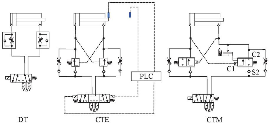
Figure 1 Investigated systems.
On the other hand, the mechanical solution does not require sensors or the programmable logic structure needed by the electronic solution for a timely shut-off. This reduces the system complexity and overall commissioning effort. The mechanical shut-off is based on the pneumatic detection of the cylinder’s end position, signalled by a sudden drop in back pressure. This well-known principle is employed in some commercially available valves, which sense if the back pressure falls below a threshold to detect when a cylinder reaches the end of its stroke [30, 31]. It is considered advantageous to integrate the shut-off function directly into the upstream valve itself to reduce complexity and component requirements. This is possible because the back pressure acts on the control surface of the upstream valve. Thus, the pressure drop can be detected as a sudden change in the valve spool position. A more detailed description of how this was implemented will be provided using Figure 2.
It should be noted that recognizing the end position via a back pressure drop can lead to a premature shut-off of the air supply if the cylinder experiences excessive counterforce mid-stroke or is blocked. Thus, this simpler approach reduces the robustness of the shut-off function.
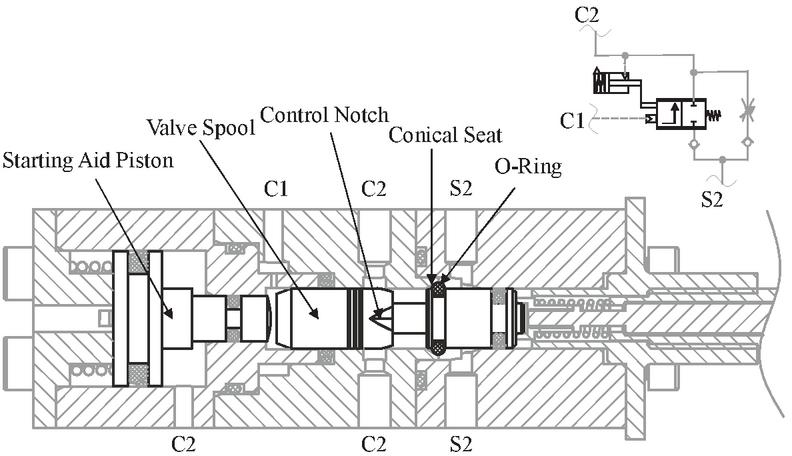
Figure 2 Design of the upstream valve with mechanical shut-off and starting aid.
Since both combined throttling systems (CTM and CTE) share the same functionality while the cylinder is moving and only differ in how the shut-off is accomplished, only one prototype for both systems was developed and manufactured in this study. A sectional view of the upstream valve is shown in Figure 2. The air supply from the directional control valve is connected at ports S2, while the pneumatic cylinder is connected to the upstream valve at ports C2. The back pressure, as a control variable, corresponds to the pressure in the counteracting chamber and is connected to port C1.
The valve spool throttles the air to the active cylinder chamber through a defined notch geometry depending on the back pressure level. The design method for the notch geometry will be described in Section 3. In addition to this main function, the mechanical shut-off is also integrated into the spool and takes the form of an O-ring and a conical seat. In the event of a sudden drop in back pressure, the controller spring moves the valve spool to the left and presses the O-ring against the conical seat, tightly blocking further air supply to the active chamber. For the electronic implementation of the shut-off, this O-ring is removed.
Furthermore, the mechanical shut-off requires a starting aid on at least one of the upstream valves because otherwise, insufficient pressure in both cylinder chambers would result in a deadlock. The starting aid is implemented as a piston, which overrides the shut-off function. If the pressure in the driving chamber falls below a threshold, the starting piston pushes against the valve spool, thus lifting the shut-off O-ring from its conical seat. In the case that the electronic shut-off is used, the starting aid piston is locked in a fixed position, and it only acts as an end-stop for the valve spool.
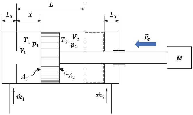
Figure 3 Modelling of a pneumatic cylinder.
3 Model Based Design
3.1 Modelling of Pneumatic Drives
Figure 3 shows a schematic illustration of the modelling used in this work. The position of the piston is labelled and the constant is used for travel length. Furthermore, the dead volumes in the cylinder end positions are assumed to be symmetrical and considered using the length .
The mechanical modelling of the pneumatic cylinder is achieved by Newton’s second law, which describes the forces acting on the mass . The forces resulting from pressure in the chambers and ambient pressure are multiplied by their respective areas. The frictional force is described using a Stribeck curve, which defines the frictional force as a function of speed and pressure in three characteristic ranges (boundary lubrication, Coulomb friction, and viscous friction). Additionally, an external load force can be introduced in the modelling.
| (1) |
For the thermodynamic modelling of the pressure dynamics a polytropic model commonly used in the literature was chosen [32–34], where is the ideal gas constant and the temperature of the compressed air supply.
| (2) | ||
| (3) |
A modelling of the chamber temperatures is also necessary for the complete modelling of the polytropic model. In the literature, the polytropic relationship for a closed volume is often used for this purpose [33], as shown in Equation (4).
| (4) |
The calculation of mass flows through throttles and valves is achieved by using the equations for technical resistances in accordance with ISO 6358-1 [35], considering the current operating states according to Equation (5) or Equation (6). The mass flow is primarily characterized based on the density at standard conditions, the upstream pressure , downstream pressure , and the conductance . Furthermore, depending on the critical pressure ratio , the mass flow can be either supercritical or subcritical.
| (5) | ||
| (6) |
The pneumatic lines were modelled with a static model, considering the dead volumes and the resistance using the empirical formulas for and proposed in ISO 6358-3 [36], where is the tube diameter and the tube length.
| (7) | |
| (8) |
3.2 Design Method
While the previously shown model allows for the nonlinear simulation of the cylinder dynamics, a simplified linear model is employed for controller design. This facilitates an easy assessment of closed-loop stability and aids in shaping the opening characteristics of the upstream valve. The following assumptions were considered in formulating the model:
• All temperatures in the pressure differential equations are assumed to be constant (). This is a commonly used assumption in the controller design of servo-pneumatic cylinders to reduce model order, as Equation (4) is omitted [33, 34].
• The plant or cylinder model was linearized at a midstroke position through a first-order Taylor expansion (.
• Dynamics of the upstream valve are neglected. It is assumed that the upstream valve has a much higher eigenfrequency than the cylinder.
• Outflowing mass flow through the downstream throttle is always assumed to be supercritical (). This assumption is based on the backpressure being regulated to be at least high enough to achieve supercritical flow.
• Inflowing mass flow through the upstream valve is also assumed to be supercritical. An investigation of the closed-loop poles concluded that the impact of this assumption is minimal for the relevant pressure gradient.
The resulting model in state space is presented in detail in [26]. With this simplified model of the plant, closed-loop stability can be assessed for different plant parameters using disk margin analysis or other stability analysis methods. Conversely, by evaluating the back pressure at the steady-state operating point, it can be determined whether the valve has sufficient conductivity to generate the required back pressure. The authors demonstrated that a linear opening characteristic is inadequate for reliable operation across a broad range of parameters [26]. Consequently, a non-linear metering characteristic was designed. The schematic representation of the main characteristic of the designed metering edge geometry are shown in Figure 4.
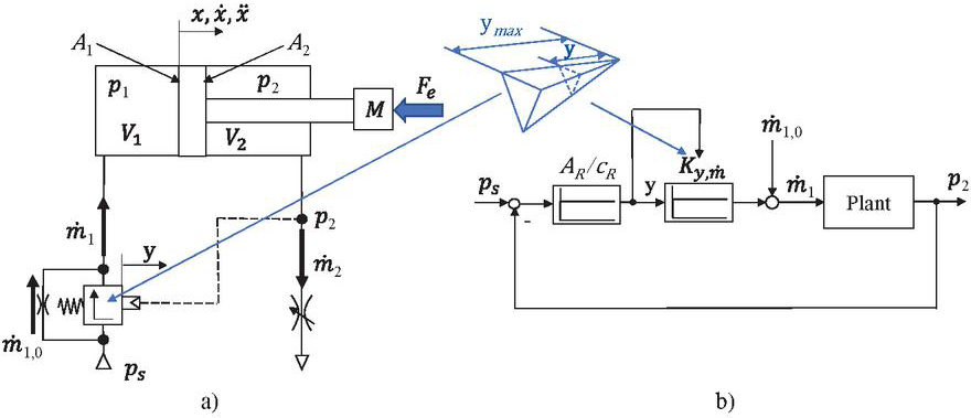
Figure 4 Schematic representation of the control edge design.
The edge geometry consists of control notches as a mechanical implementation of a gain-scheduling approach. Gain scheduling is an adaptive control method, in which the parameters of a linear controller are changed dynamically as a function of one or more “scheduling” variables [37]. Ideally, the scheduling variable for the controller should be the mass flow requirement of the cylinder. This way, the controller uses low gains for slow cylinder speeds, increasing the gain as the mass flow requirement rises. In this case, the steady-state error is utilized. Allowing for a higher mass flow requires the upstream valve to open further, resulting in lower back pressure. With the linear model it is possible to calculate the opening position of the valve and the corresponding gain factor of the controller for different operating points, thus allowing for a targeted tuning of the expected behavior.
Figure 5 shows the final notch geometry. The diagram also illustrates the mechanical-pneumatic shut-off function towards the end of the stroke, which is indicated by the red dashed line. A small opening in the neutral position has been introduced, which can be interpreted as a feedforward control. In this way, the conductivity and response behavior of the upstream valve can be improved without increasing the gain factor and thereby compromising stability. The effects of this measure are illustrated in Figure 5(right). In comparison to the control edge in Figure 5(left), the steady-state operating points shift to the left. This implies that the valve needs to open less to achieve the same mass flow, resulting in a better distribution of the steady-state operating points across the valve stroke. However, when choosing the size of this opening, it is key to consider the minimal required mass flow.
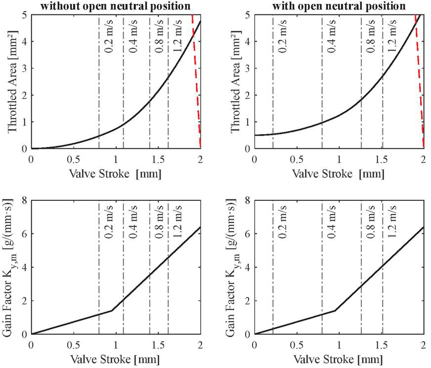
Figure 5 Control edge geometry and operating point distribution for ø 32 mm Cylinder during the extending stroke.
3.3 Simulative Investigation
The design method presented in Section 3.2 proved to be an effective tool for generating different control edge geometries. However, these geometries were also tested with a non-linear simulation model at different parameters and then adapted. This iterative development process is key to achieve a satisfactory design for multiple applications.
An important parameter for the system dynamics, which is not considered by the linear model, is the residual pressure in the drive chamber at the end of the movement. The residual pressure corresponds to the initial back pressure when the direction of cylinder movement changes. The importance of the initial back pressure for the system dynamics results from the fact that it has a significant influence on the opening behavior of the upstream valve. Figure 6 shows simulation results of an extending cylinder with different initial back pressures, while all other parameters are kept constant. It can be observed that the upstream valve opens later at higher residual pressures, which leads to longer cycle times. The cycle time is therefore heavily dependent on the residual pressure.
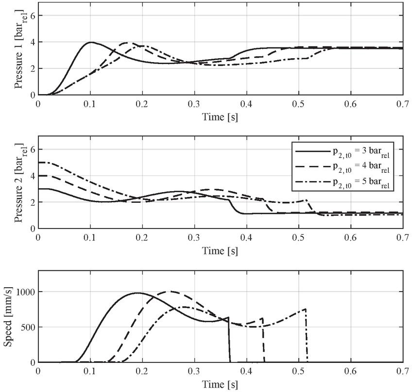
Figure 6 Simulation results with different initial back pressure levels.
4 Experimental Set-Up and Methodology
For the experimental validation, the test rig shown in Figure 7 was employed. The test rig facilitates the investigation of a test cylinder performing point-to-point motion tasks under various conditions. To simulate diverse operating conditions, different load masses, cylinder sizes, friction forces and orientations were utilized. The load masses are mounted on a roller guide, which is exposed to varying levels of friction through a brake unit.
The air consumption and dynamic behaviour of the cylinder with different system architectures was tested. Depending on the system, the 5/3 directional control valve can be operated as a 5/2 directional valve if the neutral position isn’t required. To measure the cylinder stroke and speed an incremental encoder was used. An accumulator with a 20-liter volume was installed between the mass flow sensor and the 5/3 directional control valve. The accumulator serves to dampen air flow fluctuations and prevent measurement errors caused by the inherent inertia of the mass flow sensor. As a result, it provides an average air flow reading rather than an exact resolution of the air flow into each cylinder chamber. However, this trade-off was accepted to ensure accurate measurement of the total compressed air consumption.
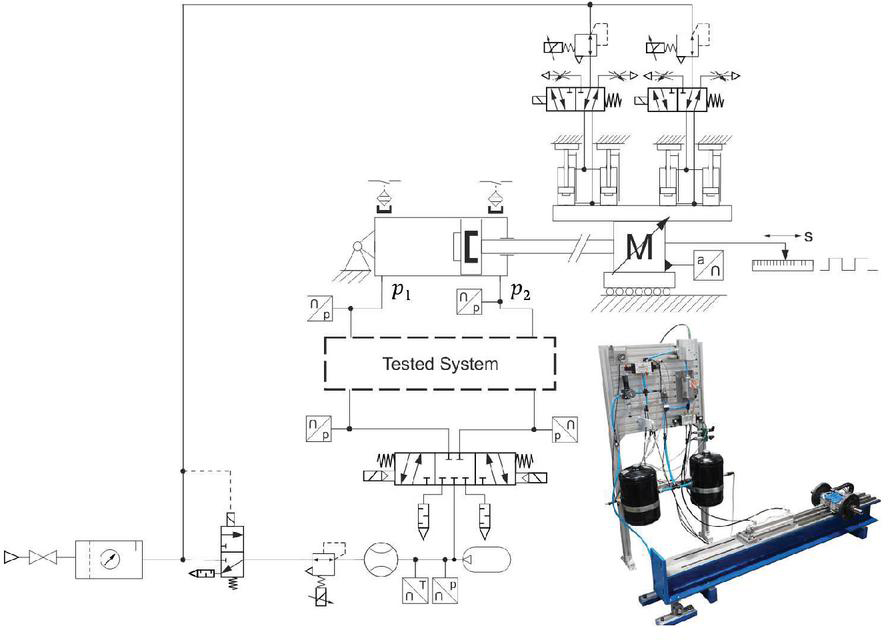
Figure 7 Test rig circuit.
4.1 Evaluation Methodology
All investigated systems were tested with different use cases, defined by a given cylinder, load mass, friction force and orientation. A total of 50 cycles were recorded for each use case following a short run-in period. The cycle time and air consumption were assessed to characterize each system. The cycle time is defined as the duration from the switch signal until the cylinder reaches the end position and includes the transfer time and delay time. Furthermore, during the experimental investigation, all systems utilized the end cushion up to its maximum loading capacity. Consequently, the minimum achievable cycle time was measured for each system, enabling an objective comparison.
Conventional downstream throttling is used as the reference system for cycle time and compressed air savings. To check the correct dimensioning of the downstream throttled drives, the use cases were evaluated with the design guideline according to Doll [3], which is based on the cylinder eigenfrequency. It should be noted that the eigenfrequency is approximated by using a rod-less cylinder in mid-stroke and by considering that both chambers and dead volumes in the lines are pressurized with supply pressure .
| (9) |
Doll’s guideline relates the transfer time with the eigenperiod to calculate the dimensionless “pneumatic frequency ratio” . In this study the average transfer time for both retracting and extending was employed. The sizing of the investigated use cases with downstream throttling according to Equation (10) is depicted in Section 5.
| (10) |
To condense the experimental results for easier interpretation, the relative compressed air savings and the relative increase in cycle time of the combined throttling systems are first calculated for each operating case. As previously stated, downstream throttling will be used as the reference system. In general, the combined throttling approach achieves a reduction in compressed air consumption. However, the reduced backpressure results in longer cycle times compared to downstream throttling due to the reduced performance of the end cushion.
The relative air savings of any system compared to downstream throttling can be calculated as follows:
| (11) |
Analogous, the relative increase in cycle time can be expressed as follows:
| (12) |
To enable a fair comparison of the energy efficiency between conventional downstream throttling and the novel combined throttling schemes, it is necessary to consider the interaction between an increase in cycle time and potential compressed air savings. The air consumption per cycle of a downstream throttled cylinder can be approximated with Equation (13), with being the cylinder area ratio.
| (13) |
By incorporating the design guideline presented by Doll (Equation (10)) into Equation (13), it is possible to express the cylinder’s air consumption as a function of the transfer time.
| (14) |
Assuming, the same sizing parameter “”, Equation (15) describes the relationship between compressed air consumption and cycle time of a downstream throttled actuator. Here, corresponds to the compressed air consumption at a different transfer time . Furthermore, we will use the complete cycle time instead of just the transfer time, under the assumption that the ratio of transfer time to delay time of the downstream throttled drive remains relatively constant at different pressure levels.
| (15) |
For a compressed air saving scheme to be effective, any increase in cycle time must be offset by a substantial reduction in air consumption. For example, if the cycle time of a particular scheme is double that of an optimal sized downstream throttled drive, the air consumption should decrease by at least a factor of four for the scheme to be more efficient. Otherwise, a downstream throttled drive can be sized to be more efficient at that increased cycle time. The actual reduction in air consumption of a hypothetical system, when compared to downstream throttling and regardless of cycle time, can be expressed as follows:
| (16) |
In Section 5.2, the experimental results will be visualized as data points in a diagram that plots the achieved relative air savings () over the relative increase in cycle time (). To account for the relation between changes in cycle time and air consumption of downstream throttled systems, isolines for relative efficiency increase in this plane need to be integrated. Thus, the air savings compared to an optimally sized downstream throttled system with identical deviation in cycle time and constant frequency factor compared to the experimental results get visible. For the mathematical definition of the isolines, an expression for the actual reduction in air consumption, as shown in Equation (16), is derived based on these metrics. Equation (16) can be expressed as a relative air saving as follows:
| (17) |
Finally, the relative air savings can be expressed by rearranging it as a function of the relative increase in cycle time. Equation (18) corresponds to the isolines with constant normalized air savings in Figures 11 and 12.
| (18) |
5 Results and Discussion
This section shows the experimental results. In Section 5.1, the dynamic behaviour of the different systems is compared exemplarily, while the quantitative results for all use cases are presented in Section 5.2.
Figure 8 shows the Omega values for various test scenarios. These are deduced from the cycle times of the tuned downstream throttled experimental setups for both horizontal and vertical direction of motion, although strictly speaking the design guideline is only defined for the horizontal cases. The use cases are identified according to the following nomenclature (Equation (19)). The friction is either given by a number, which corresponds to the friction force in Newton or the letter R, which stands for rolling friction, the lowest achievable friction on the test rig rolling friction.
| (19) |
For all cases investigated, the downstream throttled cylinders are either well dimensioned or slightly oversized. Thus, these cases provide a good reference for investigating the energy saving measures. It should also be noted that already in the publication of the design guideline, longer cylinders tend to lead to higher omega values for optimal design.
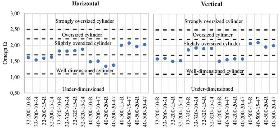
Figure 8 Omega-values of investigated load cases.
5.1 Dynamic Behaviour
Figure 9 shows the measured data for load case 32-200-10-R in the horizontal orientation. As expected, the combined throttling systems (CTM and CTE) exhibit significantly lower back pressures, resulting in lower driving pressures during cylinder movement compared to downstream throttling (DT). Additionally, after reaching the end position, the pressure in the active chamber of the downstream throttled cylinder rises to supply pressure (6 bar) due to the lack of a shut-off. In contrast, both the mechanical and electronic shut-off solutions effectively cut off the pressure supply after reaching the end position, preventing further pressurization of the active cylinder chamber.
The different execution of the shut-off function results in a different behaviour between CTM and CTE. Due to the simultaneous blocking of the supply and return path using a 5/3 valve as a shut-off, CTE retains residual pressure in the counteracting chamber. In the case of the mechanical shut-off, only the supply path to the driving chamber is blocked by the upstream controller itself, leading to a complete relief of pressure in the counteracting chamber.
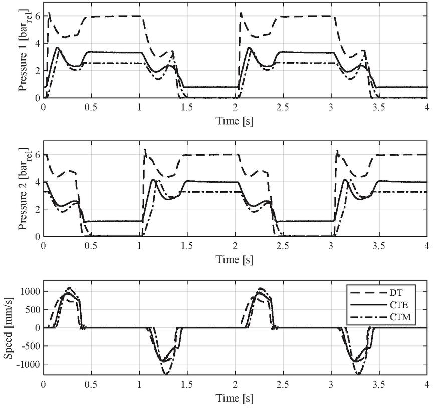
Figure 9 Dynamic behaviour in horizontal orientation 32-200-10-R.
Figure 10 illustrates the dynamic behavior of all systems in a vertical cylinder orientation, with the mass being raised on the extending stroke. The driving pressure of the downstream throttled drive (DT) remains consistent when compared to the horizontal orientation (refer to Figure 9). However, the back pressure during the extending stroke is significantly reduced, and the back pressure during retraction is increased due to the weight force assisting or acting against the cylinder movement, respectively. This effect aligns with the expected impact of external forces on downstream throttling.
Compared to conventional downstream throttling, combined throttling (CTE and CTM) shows a reduced change of the back pressure, since it’s controlled by the upstream controller. In contrast, during extension, the counteracting weight force leads to a higher driving pressure. Similarly, during retraction, there is a dramatic decrease in driving pressure compared to the horizontal orientation. Therefore, the automatic load-adaptive property of the concept is evident in the measured results.
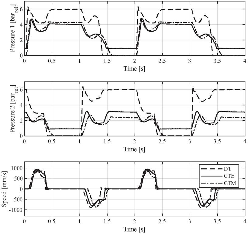
Figure 10 Dynamic behaviour in vertical orientation 32-200-10-R.
5.2 Efficiency Maps
As previously explained, the isolines in the efficiency maps, as shown in Figures 11 and 12, correspond to Equation (18) and represent constant normalized air savings. The isoline marked with a zero represents neither an improvement nor a worsening when compared to downstream throttling. Operating cases to the left of this isoline indicate an improvement, whereas those to the right indicate a worsening. The numbers on the isolines represent the percentage efficiency advantages.
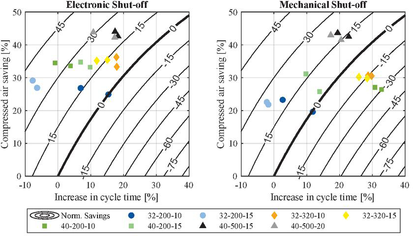
Figure 11 Experimental results in horizontal orientation.
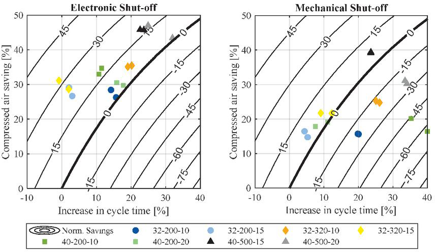
Figure 12 Experimental results in vertical orientation.
The results of the horizontal cylinder show a high dispersion. However, similar high savings in compressed air can be observed for both systems for all operating cases, ranging from 25% up to 45%. Nevertheless, due to an increase in cycle time the normalized air savings are generally lower. The system with mechanical shut-off specially exhibits negative normalized air savings in certain operating cases, despite achieving compressed air savings of nearly 30% in those instances. Consequently, due to the increased cycle time, the system performs worse than optimally sized downstream throttling in these situations.
The higher increase in cycle time of the mechanical solution is partially explained due to the activation of the mechanical shut-off at higher air flow demands. This limits the maximum setting of the downstream throttle, thus increasing the cycle time compared to the system with electronic shut-off.
In the vertical orientation of the cylinder, the use of a mechanical shut-off results in higher compressed air consumption compared to electronic shut-off. During the return stroke, the weight force assists cylinder movement, reducing the driving pressure in the rod chamber. However, with the mechanical shut-off, the starting aid prevents the drive pressure in the rod-side chamber from falling below a threshold value, leading to increased air consumption compared to the electronic shut-off function. This ultimately results in higher overall normalized “” air savings for the electronic solution. A similar phenomenon was observed in the simulative study presented in [26].
The results presented in this section regarding the normalized air savings are to be understood as a comparison with an ideally sized downstream throttled drive, representing the worst-case scenario for the air-saving scheme. However, in practice, drives tend to be oversized, e.g. due to a limited number of available cylinder diameters. For an oversized drive, the actual savings of the combined throttling system will be closer to the measured compressed air savings.
6 Summary and Conclusions
The paper presents a comprehensive simulative and experimental study of a novel combined throttling switching scheme for compressed air savings on pneumatic actuators. It provides an overview of the design process, main characteristics of the novel systems, and an experimental investigation of three different pneumatic circuits: a conventional downstream throttled drive, combined throttling with electronic shut-off, and combined throttling with mechanical shut-off. Furthermore, a metric for comparing air savings adjusted to changes in cycle time was introduced, allowing for an objective comparison to conventional downstream throttling. The results demonstrate a significant improvement in normalized air consumption with the novel circuits, although a high variation in performance was observed for different use cases. In some cases, the mechanical shut-off resulted in a worsening of the normalized air consumption. The main characteristics of the investigated system can be summarized as follows:
• Combined throttling achieves significant compressed air savings (30–45%), but the lower back pressure results in longer cycle times. Thus, the normalized performance adjusted for changes in cycle time shows a high variation over the investigated use cases.
• The system is load adaptive and automatically adjusts the driving pressure to external forces. However, changes in initial back pressure impact cycle time considerably.
Acknowledgement
The IGF research project 21381 N / 1 of the research association Forschungskuratorium Maschinenbau e. V. – FKM, Lyoner Straße 18, 60528 Frankfurt am Main was supported from the budget of the Federal Ministry of Economic Affairs and Climate Action through the AiF within the scope of a program to support industrial community research and development (IGF) based on a decision of the German Bundestag. Furthermore, the authors would like to thank the accompanying project committee for their support and technical discussions.
References
[1] Festo Corporation, “Pneumatic Sizing”, accessed December 5, 2023, https:/www.festo.com/eap/en-us\_us/PneumaticSizing/.
[2] Emerson Corporation, “Numasing”, accessed December 5, 2023, https:/www.asco.com/en-us/Pages/calculators-numasizing.aspx.
[3] M. Doll, R. Neumann, O. Sawodny, ‘Dimensioning of pneumatic cylinders for motion tasks’, International Journal of Fluid Power, 16(1): 11–24, 2015.
[4] M. Doll, ‘Optimierungsbasierte Strategien zur Steigerung der Energieeffizienz pneumatischer Antriebe’, Dissertation University of Stuttgart, 2016.
[5] A. Raisch, O. Sawodny. ‘Analysis and optimal sizing of pneumatic drive systems for handling tasks’, Mechatronics, 59: 168–177, 2019.
[6] P. Harris, S. Nolan, G. E. O’Donnell. ‘Energy optimisation of pneumatic actuator systems in manufacturing’. Journal of Cleaner Production, 72:35–45, 2014.
[7] J. Hepke, J. Weber, ‘Energy saving measures on pneumatic drive systems’ 13th Scandinavian International Conference on Fluid Power, 092: 475–483, Linköping, Sweden, June 3–5, 2013.
[8] G. Harimoto, M. Senoo, Y. Fujiwara, ‘Fluid Circuit of Air Cylinder’, Patent US 11,118,606 B2, 2021.
[9] J.J. Cummins, S. Thomas, C.J. Nash, S. Mahadevan, D.E. Adams, E.J. Barth, ‘Experimental Evaluation of the Efficiency of a Pneumatic Strain Energy Accumulator’, International Journal of Fluid Power, 18(3): 167–180, 2017.
[10] D. Müller, et al., ‘Energy Efficient Pneumatics: Aspects of Control and Systems Theory’, International Journal of Fluid Power, 23 (3): 299–342, 2022.
[11] M. Novakovic, et al., ‘Impact of Capturing Used Air on the Dynamics of Actuator Drive’, Control Engineering and applied informatics, 17 (2): 82–89, 2015.
[12] E. Rakova, J. Hepke, J. Weber, ‘Comparison of Methods for the Investigation on the Energetic Behaviour of Pneumatic Drives’, 9th International Fluid Power Conference (IFK), 1: 116–127, Aachen, March 24–26, 2014.
[13] T.J. Gibson, E.B. Barth, ‘Design, Model, and Experimental Validation of a Pneumatic Boost Converter, Journal Dynamic Systems, Measurement and Control, 141(1): 011004, 2019.
[14] S. Merkelbach, H. Murrenhoff, ‘Turning challenges into opportunities in the data center’, Symposium on Fluid Power and Motion Control, Chicago, USA, October 12–14, 2015.
[15] M. Heitmann, T. Hergenröther, ‘Fluidrückführvorrichtung für einen doppeltwirkenden Zylinder und Verfahren zum Betreiben eines solchen Zylinders’, Patent DE 10 2019 121 433 A1, 2019.
[16] M. Heitmann, F. Rein, ‘Energy efficiency in pneumatics with the ’Air Saving Box’: the revolutionary plug & play solution from SMC’, 12th International Fluid Power Conference (IFK), Dresden, Germany, October 12–14, 2020.
[17] P. Harris, S. Nolan, G. O’Donnell, ‘Energy optimization of Pneumatic Actuator Systems in Manufacturing’, Journal of Cleaner Production, 259–270, 2014.
[18] A. Raisch, S. Hülsmann, O. Sawodny, ‘Saving Energy by Predictive Supply Air Shutoff for Pneumatic Drives’, Proceedings of the European Control Conference (ECC), 965–970, Limassol, Cyprus, June 12–15, 2018.
[19] M. Doll, O. Sawodny, ‘Energy Optimal Open Loop Control of Standard Pneumatic Cylinders’, 7th International Fluid Power Conference (IFK), 4: 256–270, Aachen, March 22–24, 2010.
[20] M. Doll, R. Neumann, O. Sawodny, ‘Energy Efficient Use of Compressed Air in Pneumatic Drive Systems For Motion Tasks’, International Conference on Fluid Power and Mechatronics (FPM), 340–345, Beijing, China, August 17–20, 2011.
[21] D. Rager, M. Doll, R. Neumann, M. Berner, ‘New programmable valve terminal enables flexible and energy-efficient pneumatics for Industry 4.0’, 11th International Fluid Power Conference (IFK), Aachen, 2018.
[22] R. Neumann, D. Rager, M. Doll, ‘Verfahren zum Betreiben einer Ventileinrichtung, Ventileinrichtung und Datenträger mit einem Computerprogramm’, Patent DE 10 2016 206 821 A1, 2016.
[23] Festo Corporation, ‘Energieeffizienz@Festo’, White Paper, 25, 2014
[24] D. Šešlija, S. Dudić, I. Milenković, ‘Cost Effectiveness Analysis of Pressure Regulation Method on Pneumatic Cylinder Circuit’, International Energy Journal, 17 (2): 89–98, 2017.
[25] O. Reinertz, K. Schmitz, ‘Optimized Pneumatic Drives through Combined Downstream and Adaptive Upstream Throttling’, Symposium on Fluid Power and Motion Control (FPMC), Bath, United Kingdom, September 9–11, 2020.
[26] C. Reese, O. Reinertz, K. Schmitz, ‘Energy Savings through Adaptive Upstream Throttling and Supply Shut-Off on Downstream Throttled Drives’, Chemical Engineering and technology, 46: 137–146, 2022.
[27] O. Reinertz, K. Schmitz, ‘Gasbetriebenes Antriebssystem und Verfahren zum Betrieb’, Patent WO2022049298A1, 2022
[28] F. Nazarov, J. Weber, ‘Sensitivity Analysis and Robust Optimization of an Integrated Pneumatic End-Position Cushioning’, 13th International Fluid Power Conference (IFK), Aachen, Germany, pp. 974–988, June 13–15, 2022.
[29] P. Beater, ‘Pneumatic drives: System Design, Modelling and Control’, Springer Verlag, Berlin, 2007.
[30] Festo Corporation, ‘Cylinder signal generator PPL’, Product data sheet, 2023.
[31] Parker Corporation, ‘Parker Legris, Fluid System Connectors’, Product catalogue, 123-124, Otsego, USA, 2023.
[32] O. Ohligschläger, ‘Pneumatische Zylinderantriebe – thermodynamische Grundladen und digitale Simulation’, Dissertation, RWTH Aachen, 1990.
[33] J. Falcao Carneiro, F. Gomes de Almeida, ‘Reduced-order thermodynamic models for servo-pneumatic actuator chambers’, Proceedings of the Institution of Mechanical Engineers Part I Journal of Systems and Control Engineering 220(4): 301–314, 2006.
[34] M. Göttert, ‘Bahnregelung servopneumatischer Antriebe’, Dissertation, Universität Siegen, 2004
[35] International Standard, ‘ISO 6358-1: Pneumatic fluid power – Determination of flow-rate characteristics of components using compressible fluids – Part 1: General rules and test methods for steady-state flow’, 2013.
[36] International Standard, ‘ISO 6358-3: Pneumatic fluid power – Determination of flow-rate characteristics of components using compressible fluids – Part 3: Method for calculating steady-state flow-rate characteristics of systems’, 2014.
[37] D. Leith, W.E. Leithead, ‘Survey of gain-scheduling analysis and design’, International Journal of Control, 73(11): 1001–1025, 2010.
Biographies

Christian Reese Jimenez received the bachelor’s degree in mechanical engineering in 2017 and the master’s degree in general mechanical engineering from RWTH Aachen University in 2019. Since 2019, he is working as a Research Associate at the Institute for Fluid Power Drives and Systems (ifas), RWTH Aachen University. His research areas include simulation and optimization of fluid power systems and components focusing on enhancing energy efficiency and performance.

Olivier Reinertz received his diploma and his doctoral degree in mechanical engineering from RWTH Aachen University, Germany. He is currently Scientific Director at the Institute for Fluid Power Drives and Systems (ifas) at RWTH Aachen University. His research focuses on the model-based analysis of fluid power components and systems and the derivation and validation of innovative strategies for efficiency and performance optimization with an emphasis on compressed air and gas-powered systems.

Katharina Schmitz received a graduate’s degree in mechanical engineering from RWTH Aachen University in 2010 and an engineering doctorate from RWTH Aachen University in 2015. She is currently the director of the Institute for Fluid Power Drives and Systems (ifas), RWTH Aachen University.
International Journal of Fluid Power, Vol. 25_1, 1–26.
doi: 10.13052/ijfp1439-9776.2511
© 2024 River Publishers


