Review of Fault Detection and Diagnosis Methods Including Failure Root Causes of Major Components of Hydraulic Pitch System for Wind Turbines-Part-I
Gyan Wrat1, Mohit Bhola1,*, Diego M. Chamorro1, Jesper Liniger2 and Henrik C. Pedersen1
1AAU Energy, Mechatronics Section, Aalborg University, Aalborg, Denmark
2AAU Energy, Esbjerg Energy Section, Aalborg University, Esbjerg, Denmark
E-mail: mobh@energy.aau.dk
*Corresponding Author
Received 03 May 2024; Accepted 29 August 2025
Abstract
The hydraulic pitch system is one of the critical sub-systems of the wind turbine for both power regulation and also as part of the safety system by applying aerodynamic braking during the duration of extreme weather events. Various studies of wind turbine reliability have revealed that the hydraulic pitch system is one of the major contributors to the turbine’s downtime. Therefore, the focus of this study deals with the identification and mapping of failures in hydraulic pitch systems and the main components based on state-of-the-art failure mode knowledge and detection methods found in the literature. In this work, Fault Tree Analysis (FTA) is utilized to evaluate failures all the way down to root causes of major hydraulic components, i.e., on-off solenoid valves, proportional valves, hydraulic cylinders, and sensors used in hydraulic pitch systems. This facilitates a comprehensive understanding of failure modes and root causes within these hydraulic components. Nevertheless, the focus of this study has hence been to identify the methods to enhance fault detection and predictive maintenance strategies, ultimately improving the reliability and efficiency of hydraulic systems across various applications.
Keywords: Hydraulic pitch system, wind turbine, fault tree analysis, failure root causes.
1 Introduction
The pitch system in a wind turbine is utilized to regulate the extracted wind power during variations in the wind speed by changing the blade angle of rotation. The blade angle rotates from to around its axis, with peak power extraction occurring at and zero power at , which is also referred to as the neutral position. The setting is engaged when wind speeds surpass the turbine’s safe limit or to halt turbine operation to prevent additional damage during turbine system failures [1]. Hence, the pitch system acts as both a power regulation device and the safety system of the wind turbine but is, at the same time, one of the major contributors to the downtime of wind turbines. Thus, the hydraulic pitch system is a critical sub-system of wind turbines, and its failure can lead to significant to both economic losses, safety hazards, and reduced power production.
Several recent studies have focused on analyzing failure rates, repair processes, and fault detection techniques for hydraulic pitch systems in wind turbines [2, 3, 4, 5, 6]. These studies highlight the importance of understanding the failure modes, fault detection and diagnostics methods related to major components such as cylinders, bearings, and loose mounting, which can lead to poor pitch performance and aerodynamic imbalance.
It has been observed that the hydraulic pitch system accounts for up to 23% of all the downtime and 21% of the total failure rate of wind turbines. This data was analyzed for a 2 MW nominal power turbine, also known as R80 configuration [7, 8]. Therefore it’s important to focus on the failure analysis, condition monitoring, fault detection, and remaining useful life estimation for the critical hydraulic components used in the pitch system. However, the study was done in the year 2011 and the data was valid for old turbines. In relatively newer studies published in the year 2015 by Carroll et al. [9] for 2-4MW turbines, the hydraulic pitch system contributes 13 % to the overall failure rate. In the study, the average repair time for the pitch system varies from 9 to 25 hours, depending upon the type of replacement. However, the repair time is calculated as the actual working time by technicians for the replacement of the turbine without considering the lead time, waiting time, etc. However, it is only these few projects in the past that have focused on failures in the hydraulic pitch system, although this is one of the major failure sub-systems of wind turbines.
Furthermore, currently, as per industry experience, the wind turbines perform pre-start-up test functions conditions to test the condition of the components used in the pitch system. However, most of these tests are related to comparing the sensor signals, i.e., time or measured quantity, with some pre-defined threshold, which may have several limitations. This approach is often shallow, capable of detecting only faults that exceed simple thresholds, while subtle or early-stage issues go unnoticed. Additionally, the tests are sensitive to sensor noise and environmental factors, which can result in false alarms or missed detections. The reliance on static thresholds further limits their effectiveness, as these thresholds do not adapt to component aging or changes in operational conditions. Moreover, these tests are unable to predict the remaining useful life (RUL) of components or indicate root causes, providing only basic fault indications without deeper insights.
Hence, the motivation of this article is to provide an overview of state-of-the-art technologies and innovations for identifying faults in major components used in fluid power/hydraulics pitch systems. However, the techniques studied in this article are also valid for other fluid power/hydraulics applications. The key components include gear pumps, on-off solenoid valves, proportional valves, relief valves, hydraulic cylinders, accumulators, hoses, hydraulic oil, and sensors. For each component, the article utilizes Fault Tree Analysis (FTA) and discussion up to the root causes of faults or failure modes, as identified in recent literature, which enables targeted interventions and enhancing reliability. Additionally, the article critically examines algorithms developed in the recent past for predicting remaining useful life (RUL) and fault identification, emphasizing their applicability for real-time implementation. The algorithms in the literature are compared based on computational requirements, sampling frequency, and the environmental conditions under which they are tested. This holistic approach ensures that the algorithms are not only efficient and adaptable to resource constraints, but also robust and reliable in real-world scenarios. Such evaluations help identify the most suitable algorithms for the real application scenario.
The content is structured into two parts based on the duty cycles of the components, distinguishing between more active and less active components. Part I focuses on components such as on-off solenoid valves, proportional valves, hydraulic cylinders, and sensors, which actively participate in pitch regulation most of the time. Part II addresses components serving as the hydraulic power source, including pumps and accumulators, as well as less active components in pitch regulation, such as relief valves, hydraulic hoses, and hydraulic oil.
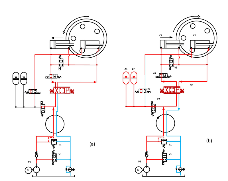
Figure 1 Hydraulic circuit of pitch system in normal power regulation operation with (a) cylinder retracting and (b) cylinder extending for each blade.
2 System Description
As described in the last Section 1, the system under focus is the wind turbine pitch system. The pitch system is a very important turbine subsystem that consists of hydraulics and an electronic control system used for obtaining the optimum power output from the turbine. The figure of the standard pitch system is shown as Figure 1. The diagram shown below illustrates a simplified pitch system, that represents the pitch system under normal operation (i.e. circuitry for start-up, emergency stopping, etc. is omitted) and only includes the valves used during normal operation of the turbine, which is the primary focus of the study.
The diagram is a simplified and generic representation of a pitch system, derived in combination with leading wind turbine OEMs, pitch system manufacturers, and turbine operators, as a good representation of the topology used by most modern pitch systems. A similar representation is used by several of the co-authors in other publications Liniger et al. [10], Yang et al. [11].
During normal operation of power regulation, the supply from the accumulators (A1 & A2) are blocked by valve V2 and energized valve V3. Hence, the hydraulic power is provided by the pump (P1) with valve V1 in energized condition. The proportional valve V6 controls the position of the cylinders C1 and C2 through valve V4 in energized condition with the position feedback loop running on the programmable logic controller (PLC). The Valve V5 connection is used during emergency shut-down with regeneration possibility and fast extension of cylinder and in normal operation the valve V6 has regeneration spool which is used for regeneration during extension. Table 1 highlights the status of on-off solenoid valves during various operating conditions.
Table 1 On-Off Solenoid valves status in terms of electrical power supply during different operating conditions.
| Valve No. | Start-up Mode | Power Regulation Mode | Emergency Shut Down | Normal Shut Down |
| V1 | On | On | Off | Off |
| V2 | On | On | Off | On |
| V3 | On | On | Off | On |
| V4 | Off | On | Off | Off |
| V5 | On | On | Off | On |
3 Fault Tree Analysis of Major Components in Hydraulic Pitch System
As shown in Figure 1, the major hydraulic components used in the hydraulic pitch system during operation are the pump, and solenoid valves, which can be on/off based upon the supervisory control using operating parameters, proportional valve, accumulators, and linear actuators. The mechanical components of the system are the main bearing for the rotating hub for the rotation of the blades. The electronic sensors like position, pressure and temperature are the necessary components, which makes it an example of a mechatronics system, with dedicated PLC for controlling and monitoring the system. Being a multi-component system, the fault-free or fault-tolerant control operation is important for obtaining satisfactory performance from the system. However, each of the components degrades with time leading to its faulty operation or complete shutdown of the turbine based on the severity of fault. So, for analyzing the faults and root cause failures in the system, a top-down approach called Fault Tree Analysis (FTA) is described for each of the components starting from the system level faults. The FTA is a logic-based technique, constructed using logic elements like OR, etc., which requires domain expertise to consider all the possible faulty conditions in the operations. The specific literature available related to pitch systems is limited to addressing the faults in the components but nothing much is said about the root cause of failures in the system [12]. So, in this article, the FTA is constructed in such a way that addresses the all root causes of failures from the materials and design perspective of the components based upon the type of failures and their mechanism shown in the past literature. The benefit of doing the component level analysis is to enhance the knowledge about the failures which leads to the improvement in design at the system and components level. The methodology of the work is explained in Figure 2.
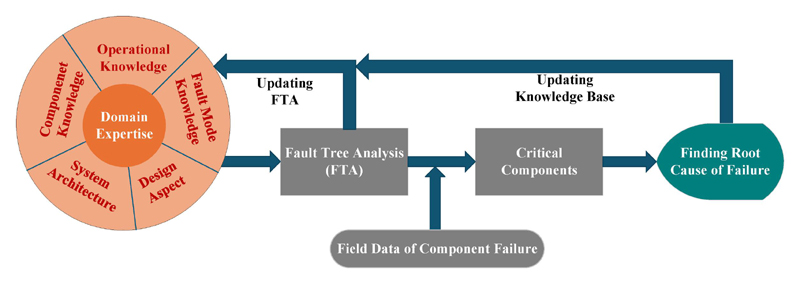
Figure 2 Flow chart for development of the FTAs.
Based upon the general topology of the pitch subsystem, the detailed FTA for each of the component in discussed in subsequent following sections. Firstly, the detailed system-level faults are described in the following subsection 3.1.
3.1 System Level Fault Tree Analysis of Hydraulic Pitch System
The system-level faults are those which occur at top level of the tree which is due to the failure occuring in the component or next subsystem level. Based upon the given topology shown in Figure 1. The top-level faults in the pitch system are described in [10] and also shown in Figure 3.
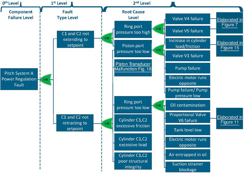
Figure 3 FTA of pitch system at system level.
The fourth level in the root cause level in 3 is described in each subsequent sections starting from Section 4.1 for solenoid valves which constitute V1-V5 in Figure 1, section 4.2 for proportional valve V6 in Figure 1, section 4.3 for hydraulic cylinder and Section 4.4 for sensors used in hydraulic pitch system.
3.2 Criteria for Algorithm Classification
Classifying algorithms is crucial for determining their applicability and compatibility with real-time systems and hardware limitations. Therefore, when considering the various algorithms, they are categorized based on their computational demands and sampling rates, ensuring an optimal fit for specific application requirements. This classification approach is applied in the following sections to evaluate and categorize the algorithms based on their computational and sampling requirements. Algorithms with high computational complexity are characterized by their substantial computational demands during real-time execution. The criteria based upon computational complexity has been defined as follows:
1. High Complexity: This refers to the high computational requirements for real-time implementation of the algorithm on a standard low performance PLC. Algorithms that fall under this category are the machine learning algorithms with high computational power in real-time inference, real-time optimization and deep neural networks. These requires specialized hardware for implementation.
2. Medium Complexity: This refers to the moderate computational requirements for real-time implementation of the algorithm on the standard low performance PLC but may require optimization for real-time execution. The algorithm falls under this category are for example adaptive controllers, look-up table based machine learning algorithms, or Kalman Filters. The balance of computational load and real-time constraints is critical.
3. Low Complexity: This refers to the minimal computational requirements for real-time implementation of the algorithm on the standard low performance PLC. The algorithm falls under this category are for example, fixed-gain PID controllers, threshold-based logic, and simple arithmetic operations which are pre-trained based upon the post-processing of data gathered by the required sensors.
For the comparison of the algorithms on sampling frequencies, the following criteria has been used:
1. High Sampling Frequency: This applies to systems which requires frequent data updates exceeding 1 kHz. Hence, it increases the computational load and limits the complexity of algorithms that can be implemented. It requires highly optimized algorithms and low-latency hardware to maintain real-time operation.
2. Medium Sampling Frequency: This applies to systems that require moderate data updates between 100 Hz to 1 kHz. It can accommodate medium-complexity algorithms, but the implementation must consider available processing resources.
3. Low Sampling Frequency: This applies to systems that require infrequent data updates, typically below 100 Hz. These are suitable for slow dynamics such as hydraulic tank level monitoring.
The selection of appropriate sampling time and model complexity is critical for successful machine learning implementations. This is evident from the extensive literature on the subject, which highlights these factors as key considerations in most applications.
The performance of machine learning algorithms is typically somewhat proportional to their complexity, making it essential to evaluate and characterize their complexity. The first stage in defining the complexity of a machine learning algorithm is batch (offline) prediction. In this stage, batches of historical datasets are post-processed, and predictions are generated at regular intervals. This approach is well-suited for applications with low latency requirements.
The next stage involves real-time inference using a pre-trained model on the batch features, which introduces additional complexity. Here, the model continues to undergo batch training while performing real-time predictions, making it more complex than the first stage. Figure 4 shows the complexity versus performance plot highlighting each of the capabilities at each stage [13].
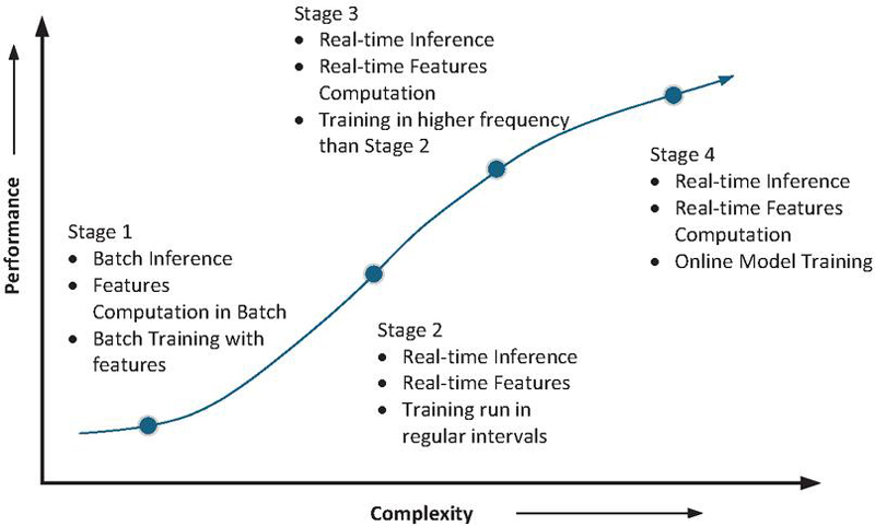
Figure 4 Performance versus complexity for machine learning algorithms.
In the third stage, models are constantly being trained with new data. This training happens more often than in the second stage. The models then make predictions in real-time using the features extracted from the current data.
The fourth stage of complexity involves real-time algorithm inference, where features are computed in real-time alongside the continuous training of models. Therefore, the comparison of ML algorithms is based on these levels of complexity. Regarding sampling frequencies, the comparison is aligned with the sensor sampling rates used to record data for extracting either pre-existing features or engineered features through feature extraction algorithms used for the training of the ML algorithm. The overview of ML algorithms which are applied to identify faults in components explained in following sections are shown in Figure 5.
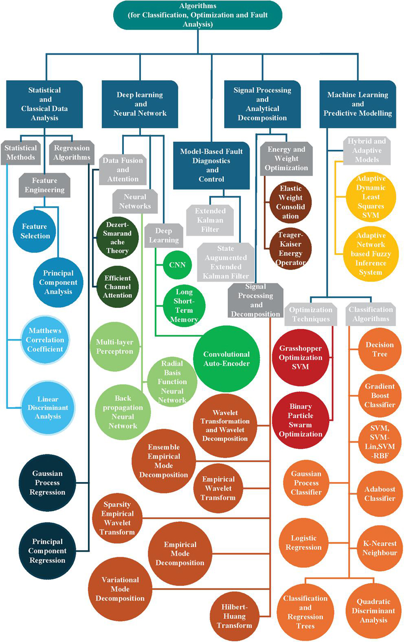
Figure 5 Cluster diagram for fault analysis in survey.
4 Major Components in Fluid Power Pitch Systems, Failures and Fault Identification Techniques
4.1 On-Off Type Solenoid Valves
The solenoid valves are some of the crucial components used in the hydraulic pitch system to shift the turbine operation mode from one to another. They can also be called an ON-OFF valve with either a normally closed and/or normally open configuration. They are shown in the Figure 1 as V1–V5. They respond to control signals from the main control system of the turbine, adjusting the turbine’s functions according to its operating conditions [14, 15, 16], as also explained in Section 2. Hence, the fault prediction of this kind of valve is very much essential. Researchers have explored various methods for predicting failure in valves, the recent ones are highlighted in this section. The pictorial view of the solenoid valve, illustrating its structural and functional components, is shown in Figure 6.
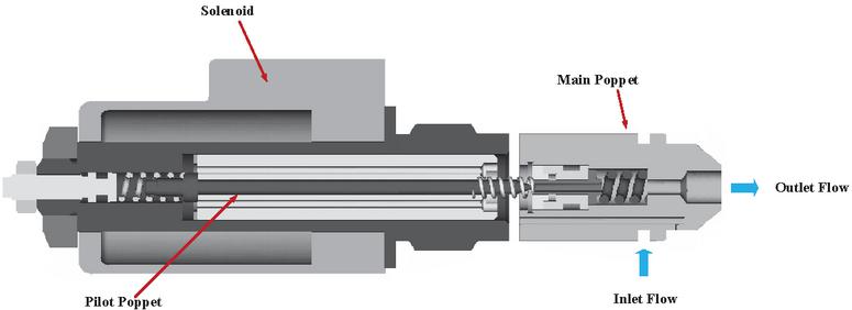
Figure 6 Solenoid valve pictorial view.
Ma et al. [17] investigated solenoid valve fault diagnosis based on analyzing the drive-end current characteristics and its second-order rate change curve under different solenoid valve conditions. This is due to back- electromagnetic force which changes due to the spool or poppet motion. Four different modes, i.e., normal valve spool, broken spring, stuck spool, and slightly stuck spool, were considered for the analysis. The proposed method utilized the characteristic curves and applied a three-layer wavelet packet decomposition (WPD) and Principal Component Analysis (PCA) for the fusion of both time and frequency domain features. Based upon the fused feature vectors obtained through WPD and PCA for different fault conditions, the authors used the C-parameter Support Vector Machine (C-SVM) with the Radial Basis Function (RBF) method for pattern recognition for each fault mode. This method achieved a 91.3% accuracy rate for the time-frequency analysis. In comparison, the Back-Propagation (BP) neural network achieved an 84.78% accuracy rate for time-frequency analysis. The proposed C-SVC method, with RBF and multi-feature fusion using both time-frequency and time-domain analysis, achieved a 100% accuracy rate, and for time-frequency analysis, a cross-validation accuracy rate of 92.11%, demonstrating its capability to classify various solenoid valve states correctly. The authors themselves in the article discussed the limitations of the work such as the machine learning algorithms, which are based on applied mathematical statistics, are not able to diagnose the fault based on root causes due to the lack of physical interpretation of experimental results.
Lei et al. [18] analyzed hydraulic valve fault diagnosis, namely valve response characteristics, using inlet and outlet pressure signals measured at ON and OFF conditions. The authors used the data from an open-source repository known as the UC Irvine Machine Learning Repository. The data were collected at the Mechatronics and Automation Technology Center of Saarbrucken University in Germany [8]. The PCA has been deployed for dimensionality reduction of the pressure signals data and eXtreme Gradient Boosting (XGBoost) for modeling on cloud platform developed by HUAWEI, named as Machine Learning Service (MLS), and proposed a highly effective fault diagnosis method by utilization of pressure signals. The integrated approach with HUAWEI Cloud MLS has contributed theoretical and practical insights for remote hydraulic component fault diagnosis and predictive maintenance. However, the paper is more about using the commercial platform for predictive maintenance developed by HUAWEI and compares the XGBoost with Classification and Regression Trees (CART) models and the Random Forests (RF) machine learning algorithms. Also, the two pressure signals used before and after the solenoid valves for response characterization did not consider the pressure dynamics due to other disturbances in the complex hydraulic circuits, and also, the dependency of operational condition requirements, which effects the ON-OFF test, are not considered.
In another work done by Shi et al. [19], the limited sensor information prompted the authors for the proposal of a two-stage multi-sensor information fusion method like fault feature fusion and decision-making information fusion for diagnosing inner faults in hydraulic directional valves. The inner faults, i.e. wear on the spool, had been created by laser (nanosecond infrared laser JTL-YLP20W) at three different levels i.e. mild wear, moderate wear, and severe wear. The EEMD and Teager-Kaiser energy operator (TEO) from the various (four) acceleration sensors were used to de-noise and obtain the fault features. The feature evaluation techniques as feature ranking and subset selection based on Euclidean distance (FRSSE) and maximum relevance minimum redundancy (mRMR) were used for feature selection with high sensitivity and good characterization with the ability to sort and threshold setting. Based on the feature selections, the CNN classifier was trained for the classification and identification of a fault. The limitation of machine learning techniques is that the physical interpretation of experimental results is not well characterized in the algorithm. The comparison was done for the single sensor without feature selection and the proposed method, which used the feature selection method. It was observed that for a single sensor without feature selection, the results were more accurate than the proposed method, but the latter was found not to be robust for a single sensor and also had less redundancy. Hence, multi-sensor data with feature fusion shows good results with the proposed method by the authors. However, the usage of multi-vibration sensors for obtaining accurate results makes the solution cost-intensive for each valve.
Yoo et al. [20] proposed a fault-diagnosis method for Hydraulic Solenoid Valves (HSVs) based on a Convolutional Auto-Encoder. The HSVs used in the study are electronic proportional pressure reduction (EPPR) valves, which are quite different from the standard ON-OFF solenoid valves. The EPPR valves are used to control the outlet pressure of hydraulic fluid by varying the input current. The valve was used to control the pressure of 25 bar. The normalized current-flux linkage data were used for the estimation of the health status of the valve, however, this type of health estimation technique can also be deployed for ON-OFF solenoid valves. The data were derived and resampled, and latent feature vectors were extracted through a one-dimensional CAE. The classification of feature vector data was clustered using hyperspheres, and fine-tuning the auto-encoder was done using a loss function for improved prediction accuracy. The experimental test-bed validated the method, which showed a higher accuracy of CAE for classification than the prediction. Also, the suggested method allowed real-time valve diagnosis using current and voltage signals without additional sensors, which is applicable through a software update to existing HSV controllers. The proposed fine-tuned CAE results in the decrease of hypersphere radius, which indicates an increase in accuracy as compared to the conventional AE method. The limitation of the work can be a non-linear change in flux linkages at the varying temperature conditions of the coil, which are not considered. A condition is also typical in the pitch system due to its varying operational conditions.
A novel fault detection method for solenoid valves, based on vibration signal measurement, was proposed by Guo et al. [21]. The valve studied was an orifice-type solenoid-operated valve used for low-pressure applications. The six fault modes described in this article are described in Table 2. The focus of the article was to predict the fault in the plunger, plunger tube, and contamination of the coil using the vibration data. The experimental data were obtained by injecting the fault by blocking the orifice, and the vibration data was collected from the sensor installed at the top of the valve body. The de-noising of the vibration signal was performed with a Wavelet-based algorithm, which determines the working state and health index, which was analyzed using the amplitude level of the vibration signal. Based upon the feature comparison with the working condition of the valve, the diagnostic decision was formed for a decision regarding the faulty and healthy valves. However, the paper does not include the effect of the amount of flow passing through the valve orifice and how this changes the data of the vibration signals. Therefore, the trained machine learning algorithm can give wrong results for different operating conditions of the valve.
An intelligent fault diagnosis approach, proposed by Ji et al. [22], utilizing DS theory, had been designed for detecting internal leakage faults in hydraulic valves, addressing the absence of specialized methods in previous research. Three classifiers, RF, LSTM, and CNN, were selected for their sensitivity to diverse fault data, fused using Dempster-Shafer (DS) theory. The experimental verification on a hydraulic valve fault testing rig demonstrated robust performance and achieved a high average diagnosis accuracy of 98.5% for six common faults, surpassing individual RF, LSTM, and CNN performances.
Table 2 shows the summary of the fault identification algorithms. The algorithms are compared based on the computational complexity and sampling frequency according to the criteria explained in Section 3.2. Particularly for the ML algorithms, the implementation level seen in literature has been also shown in Table 2.
Table 2 Recent Fault Identification Techniques and Signal Used for Solenoid Valve
| Type of Valve (Signal) | Fault Modes | Fault Identification Algorithms | Implementation & Test Conditions | Computational Complexity & Sampling Frequency |
| 4/3 Directional Control Valve (Current Signal) | Spool Stuck and Spring Break | FE = WPD & PCA FDA = C-SVM Accuracy = 91.3% |
Stage 1 Lab experiment under controlled environment [17] | High & High |
| 2/2 Directional Control Valve (Pressure Signal) | Switching Characteristic Degradation | FE = PCA FDA = XG Boost on HUAWEI Cloud based MLS Accuracy = 96.7% |
Stage 1 Lab experiment under controlled environment [18] | High & Medium |
| Directional Control Valve (Vibration Signal) | Spool Wear | FE = EEMD & TEO FS = FRSSD & mRMR FDA = CNN Accuracy = 99% |
Stage 1 Lab experiment under controlled environment [19] | High & High |
| Electric Proportional Pressure Reduction (EPPR) Valve (Current Flux Linkage) | Coil Turns Spring Stiffness and Spool Stuck | FE = CAE FDA= Hypersphere Based Classification Accuracy = 98% |
Stage 1 Lab experiment under controlled environment [20] | High & High |
| Solenoid Operated Valve (SOV) | Plunger not in action, Leakage, Pressure Loss and Magnetic Leakage | FE = Wavelet FDA = Diagnostic Decision and Comparison with healthy state Accuracy= Not Provided |
Stage 1 Lab experiment under controlled environment [21] | High & Not Provided |
| 4/3 Pilot Operated Directional Solenoid Valve (Vibration Signals) | Leakage Fault | FDA = Dempster-Shafer Fusion Theory (DSmT) Accuracy = 98.5% |
Stage 1 Lab experiment under controlled environment [22] | High & High |
| Solenoid Valve | Solenoid Coil Fault | FDA = Extended Kalman Filter Detection Probability = 97% |
Online Lab experiment under controlled environment [23] | Medium & Not Provided |
| Proportional Solenoid Valve (Voltage and Current) | Cable Solenoid Coil Spring Fault | FDA = Model Based Detection Probability = NM |
Online Lab Experiment under controlled environment [24] | Medium & High |
| ON-OFF Solenoid Valve (Current and Temperature) | Coil Burnout Fault | FDA = Model Based Accuracy = 100% |
Online Lab Experiment under controlled environment [25] | Low & Not Provided |
| 4/3 Directional Solenoid-Valve (Vibration) | Fatigue and Leakage Fault | FDA = Dempster-Shafer Fusion Theory (DSmT) Accuracy = 98.1% |
Stage 1 Lab experiment under controlled environment [26] | High & High |
| Solenoid Valve (Acceleration and Pressure) | Spool, Core Housing Wear Blocked Spool and Solenoid Failure | FE = Different Methods Accuracy = 99.72 % |
Stage 1 Lab experiment under controlled environment [27] | High & High |
* FE = Feature Extraction, FDA = Fault Detection Algorithm, FS = Feature Selection, NM = Not Mentioned
It has been noted in the ’Implementation’ column of Table 2 that the ML algorithms are implemented offline. This corresponds to the Stage 1 level of complexity in the ML domain according to Figure 4, with processing of data from sensors to evaluate engineering features and train the models followed by testing of the algorithms. The machine learning algorithms presented here can be deployed online using pre-trained models, either on a standard PLC or with an additional layer of high-performance hardware. According to the author’s recommendations, simpler algorithms are preferred for online implementation and are elloborated more in Table 9 in Section 5. To enhance algorithm performance, the models can be retrained periodically with new data. Regarding recommendation for computational complexity and sampling frequencies, the criteria mentioned in Section 3.2 has been followed.
A model-based method was proposed by Liniger et al. [23] to detect early signs of coil burnout in solenoid valves. The method employed an Extended Kalman Filter (EKF) using a thermal model by measuring coil current and voltage signals for the determination of coil resistance degradation without the need for temperature sensors. The developed technique was also able to operate at low sampling frequencies. For the simplification of the test equipment, the mechanical and thermal stresses on the coil were taken as the damage parameters. The fault in the coil was created by dropping the coil resistance with the use of a shunting resistance. The CUmulative SUM (CUSUM) of the coil current residuals was obtained by utilizing measured and estimated parameters like coil voltage, coil current, ambient temperature, and fluid temperature that indicate the coil faults. The effectiveness of the fault identification algorithm was estimated using the statistical distribution of fault instances and several fault instances before failure based on the Weibull distribution and Log-normal distribution functions. Experimental results demonstrated a high Probability of Detection before Failure (PDF) for continuous and intermittent valve excitations, validating the method’s effectiveness in alarming early signs of coil failure besides having the model inaccuracies. The effectiveness of the proposed method is shown in Table 3 in the event of a third fault instance where the algorithm is most effective. However, the fault sizes created artificially by using shunting resistance parallel to the solenoid for validation of the effectiveness of the algorithm and the fault in a real scenario may differ while measuring the performance of the algorithm.
In another model-based approach proposed by Moseler and Straky [24] for detecting faults in proportional solenoid valves used in automotive applications, voltage and current were recorded when providing a voltage step. It was done to estimate the resistance of the solenoid coil and the coil inductance for predicting the fault modes, i.e., broken cable, cable short-circuit, increased friction, and fault of adjusting screw/spring. The mechanical stroke of the solenoid armature was estimated from the measurements. These estimated measurement signals were used to categorize the fault by comparing it with the actual values. However, very high sampling rates around 10kHz were required to estimate the coil inductance.
Jo et al. [25] proposed a model-based method for detecting coil burnout in a solenoid valve under dynamic thermal loading. The valve considered was a pneumatic one that was used in railway braking applications. The authors derived an equivalent circuit model incorporating temperature effects and introduced a new health indicator for solenoid coil burnout red the health indicator being the supply current, which was compensated for its reduction with temperature rise. A case study on real solenoid valves demonstrated the method’s validity, achieving 100 % fault detection accuracy. The non-invasive method, without additional sensors, proved robust, compensating for thermal fluctuations and Joule heating, enabling solenoid coil burnout monitoring regardless of the operating temperature.
In another work by Ji et al. [26], the authors tried to extract features from the complex, noisy vibration signals coming out from the surface of the valve. The valve under investigation was a solenoid-controlled pilot-operated directional valve. The authors proposed an experimentally validated three-layer method using a Dezert-Smarandache Theory (DSmT)-based multi-classifier for feature extraction and fault prediction of multiple types. In the first layer, the fault groups were characterized into two (solenoid fatigue fault group and leakage fault group) and classified using the trained classifiers by providing personalized data sets. In the second layer, the faults were further subdivided. In the third layer, the weak features of some of the faults were classified using trained classifiers again. In a nutshell, the method involves the design of a layered hybrid model and has simplified diagnosis by breaking it into sub-tasks with multiple efficient classifiers in each layer. The fault modes considered in this study are shown in Table 2. The DSmT had acted as an arbiter for the final decision, ensuring higher accuracy and stability for each fault. Experimental verification on a hydraulic test rig demonstrated the method’s effectiveness, yielding significantly improved diagnosis accuracies, around 98.1 %, as compared to RF, CNN, and LSTM.
The comparison of accuracy levels among various algorithms, as discussed in the literature mentioned in this section, is presented in Table 3. The accuracy is as reported as seen in the different articles with the testing conditions shown in the Table 2.
Table 3 Accuracy of the Different Fault Identification Techniques in Different Works for Solenoid Valves
| Diagnosis Method | Diagnosis Accuracy | Reference |
| 1. Back Propagation (BP) Neural Networks 2. C-parameter SVM |
91.3% 84.78% |
Ma et al. [17] |
| 1.PCA-Classification and Regression Trees (CART) 2.PCA-Random Forests 3.PCA-XG Boost (Huawei MLS) |
91.1% 92.7% 96.7 % |
Lei et al. [18] |
| 1.The Proposed Method 2.EEMD+CNN+DS 3.TEO+CNN+DS |
99% 98.43% 95.56% |
Shi et al. [19] |
| 1.Proposed AE 2.Conventional AE |
7.5% to 70.5% proposed conventional AE | Yoo et al. [20] |
| 1.Dempster-Shafer (DS) theory 2.Random Forests (RF) 3.Convolutional Neural Network(CNN) 4.Long Short-Term Networks(LSTM) |
98.5% 93.2% 90.9 % 93.6 % |
Ji et al. [22] |
| 1. Back Propagation (BP) Neural Networks 2. C-parameter SVM |
91.3% 84.78% |
Ma et al. [17] |
| 1.EKF-Intermittent PDF 2.EKF-Continuous PDF |
91.1% 97 % |
Liniger et al. [23] |
| 1.Dezert-Smarandache Theory (DSmT) 2.Random Forest (RF) 3.Convolutional Neural Network (CNN) 4.Long Short-term Memory Networks (LSTM) |
98.1% 73.3% 69.9 % 65.5 % |
Ji et al. [26] |
A semi-supervised learning (SSL) method based on multi-sensor fusion and an adaptive threshold had been proposed by Zhong et al. [27] for hydraulic directional control valve and water-proof valve fault diagnosis. The focus here is to discuss the strategy of the hydraulic directional control valve as far as the hydraulic pitch system is concerned. The wear in the directional control valve core was created by using laser processing equipment. For the directional control valve, the fault modes like mild wear (0.015–0.035 mm), moderate wear (0.035–0.06 mm), severe wear (0.006 mm), wear between the valve core and housing, wear of housing, spool blocked, failure of return spring and solenoid failure were evaluated. Two pressure and two acceleration sensors were used to monitor the health of the directional control valve. The fusion algorithm was utilized to fuse the confidence of different sensor pseudo-labels and design an adaptive threshold model to select high-quality pseudo-labels. Pseudo-labels were used to expand the limited labeled data. Five different methods were used and compared with the proposed method. The proposed method tested hydraulic valve faults in different engineering fields and obtained an average diagnostic accuracy of 99.72% for the hydraulic directional valves. The obtained results show the effectiveness, enhancement, and stability of the method, improving fault diagnosis performance with less human intervention. However, the application of two pressures and two vibration sensors, which can even corrupt with environmental noise, and its dependency on installation location makes the solution costlier for the pitch system.
A comprehensive multi-physics finite element model of an automobile transmission solenoid valve, presented by Angadi et al. [28], was constructed to incorporate electromagnetic, thermodynamic, and solid mechanics effects. The model predicted susceptibility to a coupled electrical–thermomechanical failure and found that heat generated by the coil, under realistic conditions, had caused high compressive stresses and temperatures. Stresses, stemming from thermal expansion, had degraded insulation between coil wires. The resulting shorting had lowered electrical resistance, leading to eventual failure. The finite element model, validating experimentally measured temperatures, served as a predictive tool for solenoid design, offering insights into performance, life, and reliability. In continuation of the work explained in [28], an experimental rig, crafted by Angadi et al. [29], had been used to subject solenoid valves to rigorous testing, maintaining constant conditions for voltage, current, duty cycle, and frequency. Within a thermal chamber emulating automotive transmission temperatures, the critical impact of temperature on the solenoid valve reliability was observed, red which was the decrease in coil insulation. Under specific conditions, multiple test samples consistently failed, reaching temperatures of , causing complete breakdown due to insulation degradation. Predicted by a prior finite element model, this led to shorts, decreased electrical resistance, and temperatures soaring to . The obtained results show damage, including discoloration, plastic melting, and hindered plunger motion, revealing a dominant failure mechanism validated by microscale photographs displaying disorganized wire structures and insulation squeeze. However, the model requires complex FEM modeling and is also computer-intensive for the prediction of faults, but data from these types of high-fidelity models can be used for building statistical models for predicting fault types and understanding the fault behavior for design improvements based on the operating conditions of the application.

Figure 7 FTA of solenoid valve.
The recent emphasis on detecting solenoid valve faults largely relies on employing specialized machine learning algorithms. However, the majority of these algorithms are employed offline, involving post-processing sensor data through signal processing for feature extraction and subsequent training to prepare the data for predicting faults. These algorithms undergo rigorous testing within specific operational settings, some of which might coincide with the operating conditions experienced by wind turbines. Figures 7, 8 and 9 shows fault trees of the on/off solenoid valve in elaborated way.
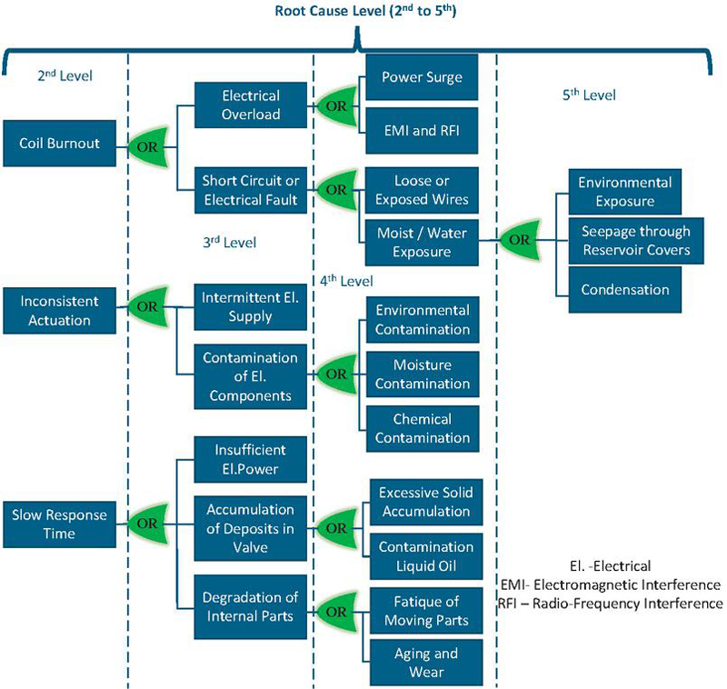
Figure 8 FTA extended from 2nd to 5th Level of Root causes for electrical failures in Solenoid Valve.
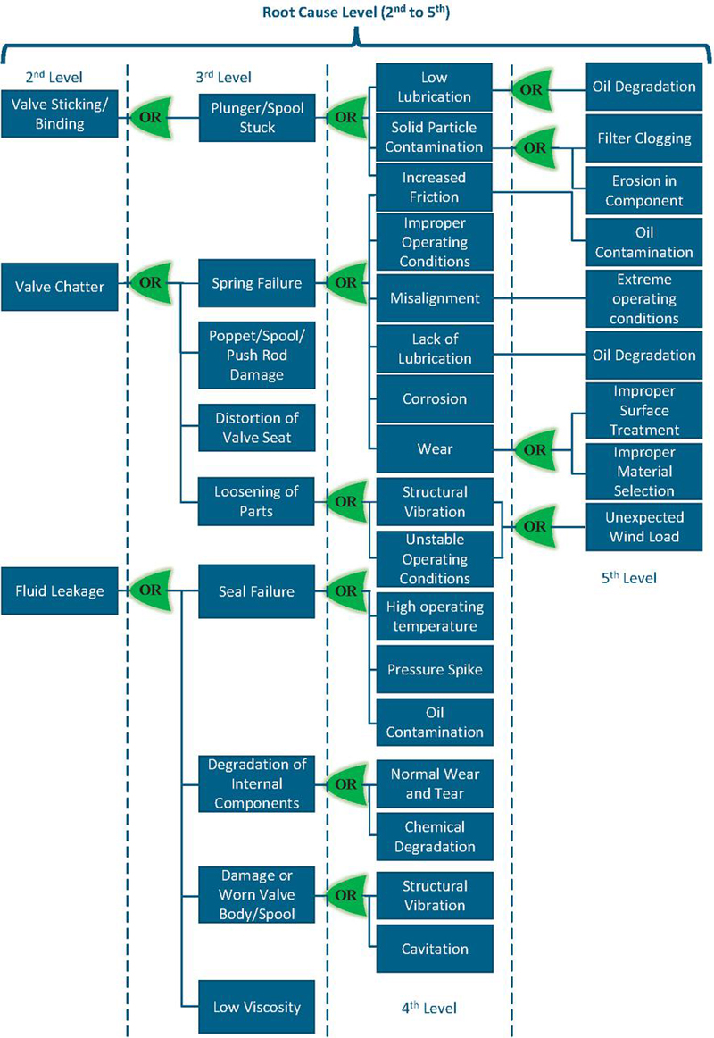
Figure 9 FTA extended from 2nd to 5th Level of Root causes for mechanical failures in Solenoid Valve.
4.2 Proportional Directional Control Valve
The hydraulic pitch system in wind turbines uses proportional valves to control the pitch angle of the rotor blades, ensuring maximum efficiency regardless of wind speed. Proportional directional valves are a key component of the hydraulic pitch system, providing accurate and high dynamic control of the blades’ angle, especially in the presence of high mechanical stress typical of onshore and offshore wind turbines [30, 31]. These valves independently change each blade’s angle facing the wind based on incoming signals from a main controller on the wind turbine, and their performance and lifetime are affected by weather conditions [32]. The hydraulic pitch system with proportional valves provides an efficient and reliable way to optimize energy production from wind turbines [30]. So, these valves are the main crucial elements of one of the critical subsystems of the turbine i.e. the hydraulic pitch system. Hence, in this section, the recent research on types of faults, predicting the faults [33], troubleshooting [34] [35], and the remaining useful life of these valves are discussed. The pictorial view of the proportional valve, illustrating its structural and functional components, is shown in Figure 10.
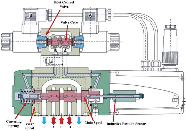
Figure 10 Proportional valve pictorial view.
Raduenz et al. [36], Bhojkar [37] described a method for online fault detection in hydraulic proportional directional control valves, with a focus on measuring valve supply current and spool position. The authors talked about how the internal closed-loop control system of the valve can compensate for spool position errors caused by various internal malfunctions. Thus, the fault cannot be identified or predicted by the spool position monitoring alone. As a result, information about the fault can be obtained from the solenoid current signal and the spool position. The dependencies of supply pressure and reference control signal were analyzed to establish thresholds for healthy valve behavior. A total of five valves were tested out of which three are double solenoid and spring centered and two are single solenoid and single spring. The method established required the prior testing for each valve to generate patterns for healthy conditions. Experimental tests on five different valves demonstrated the method’s generality and effectiveness in detecting faults i.e. spring break and spool lock, allowing for early intervention and maintenance planning. However, the detailed testing and data generation for threshold comparison of each valve model at different operating conditions needs to be characterized to that of the real operating conditions due to non-linear changes in the properties of valve components.
Reinert et al. [38] analyzed a 4/3 proportional valve with electrical position feedback, introducing various failures related to solenoids into the feedback loop. Various fault scenarios on solenoids, mentioned in this paper [38], were triggered on square and ramp reference signals and it was demonstrated, using the linear control theory, that failures could be detected by monitoring the residual signals which were generated by measuring reference and actual position signals of the spool, i.e., where the preset limit value of response time was higher than the normal response time of the valve. Also, the integration of the coil current signals provides information on faults near the zero position and failures in a closed loop. However, the load dependency of these signals for predicting the failures in the valve was also discussed as a future scope in the study.
Pedersen et al. [39] presented a fault detection algorithm for identifying coil short-circuits that applies to both ON-OFF solenoid and proportional valves. The temperature-independent method was employed using an extended Kalman filter (EKF) approach and a windowed dual-cumulative sum (CUSUM) implementation, surpassing the requirements for high-frequency measurements and temperature-dependent resistance estimation methods. The EKF was enhanced to estimate coil resistance, and windowing accommodated variations in estimated resistance due to the EKF and temperature changes. The approach consistently detected resistance changes down to 0.11 and 0.17 for constant and sinusoidal varying input signals, respectively, accurately identifying all changes amid parameter variations and increased system noise. However, dependency on a precise flux linkage approximation in the solenoid affected model precision, and including hysteresis in the flux description could further enhance results. Experimental results demonstrated the algorithm’s capability to detect a resistance drop emulating a coil short-circuit, even with significantly increased noise in the experimental setup due to the implementation of external resistance to simulate the fault.
Li et al. [40] proposed a novel fault diagnosis method for hydraulic proportional servo valves, utilizing Grasshopper Optimized Support Vector Machine (GOA-SVM). The spool movement block and solenoid aging failure were taken as fault modes in this study. The approach employed wavelet transform to denoise the spool position, pressure, and current signals, extracting time-frequency features through time domain, frequency domain, and energy entropy analyses. GOA-SVM was employed for fault pattern recognition based on the feature vectors, achieving over 95% accuracy in experiments. It found the proposed method could overcome challenges in effective fault diagnosis in practical applications, particularly for hydraulic proportional servo valves. However, feature extraction can be dependent on real-working conditions and the robustness of the proposed algorithm was only demonstrated on the laboratory scale.
Ramos Filho and De Negri [41] model efficiently determines the limits for an intact valve by estimating solenoid current in a servo-proportional valve. An error detection system that is based on rules can be created by utilizing embedded electrical controller signals and pressure measurements. Various faults like solenoid faults, spring faults, and faults due to fluid contamination with effects were discussed in this paper, which provides insightful information [42, 43, 44, 45, 46]. Even though the model is based on steady-state equations, in unfavorable circumstances, there is a sizable discrepancy between the estimated and actual current when accounting for transient pressures. When estimates from the initial spool acceleration are ignored, the model can be used for diagnosis in temporary situations. However, the sensitivity depends on the application tolerance to variations in valve behavior, fluid filtration, valve balance, and transducer quality. Table 4 The table presents recent fault identification techniques for proportional directional valves, detailing fault modes, detection algorithms, and test conditions with the implementation stage and classification of algorithms-based computational sources and sampling requirements according to criteria discussed above.
Table 4 Recent Fault Identification Techniques and Signal Used for Proportional Directional Valve
| Type of Valve (Signal) | Fault Modes | Fault Identification Algorithms | Implementation & Test Conditions | Computational Complexity & Sampling Frequency |
| 4/3 Proportional Directional Valve (Current and Spool Position) | Spool Lock and Spring Break | FDA= Empirical Regression Model Accuracy = NM |
Online Lab experiment under controlled environment [36] | Low & NM |
| 4/3 Proportional Directional Valve (Coil Currents and Spool Position) | Solenoid Based Fault | FDA= Controller Signal Based Accuracy = NM |
Online Lab experiment under controlled conditions [38] | Low & High |
| 4/3 Proportional Directional Valve (Coil Currents and Spool Position) | Solenoid Short-Circuit | FDA= EKF Accuracy = 100 % |
Online Lab experiment under controlled environment [39] | Medium & NM |
| Proportional Servo Valve (Coil Currents, Pressure and Spool Position) | Spool Block and Solenoid Aging | FE = Wavelet Transform FDA= GOA-SVM Accuracy = 97.29% |
Stage 1 Lab experiment under controlled environment [40] | High & Medium |
| Servo-Proportional Valve (Pressure and Spool Position) | Solenoid Fault Spring Fault | FDA= Model-Based Accuracy = NM |
Online Lab experiment under controlled conditions [41] | Low & NM |
| Hydraulic Solenoid Valve (Current and Vibration) | Leakage Fault | FDA= Random Forests Accuracy = 99 % |
Stage 1 Lab experiment under controlled environment [47] | High & NM |
* FE = Feature Extraction, FDA = Fault Detection Algorithm, FS = Feature Selection, NM = Not Mentioned
Conti et al. [47], presented a method for valve failure identification for a hydraulic press application, aiming for a predictive maintenance framework. The leakage fault was created on the valve with a 0.1 mm incision on the spool. Coil current and acceleration signals were used for the prediction of fault. The time and frequency domain features of acceleration signals and current signals were selected such as RMS and peak for defects. A case study was conducted using 4/3-way flow directional control valves. The flow-induced vibrations caused by leakage were seen to be captured by 20–-25 kHz acceleration RMS signals, and temporal signals for current after 0.1 s of valve actuation were shown to be significant for fault identification. Furthermore, it was mentioned that the algorithms might not be able to accurately identify leakage faults with less than 0.1 mm of incision. Therefore, to detect early failure symptoms, the spectral feature extraction and data fusion techniques were enhanced. Results from a particular case study were compared with five machine learning methods, and it was found that a data fusion process combining vibration and current data with a random forest (RF) model produced predictions with a Jaccard index that was over 99%. The work was done on an ON/OFF directional control valve, but proportional valves can also use a similar approach to identify leakage faults. Table 5 discusses the accuracy of various fault identification techniques used in different studies for hydraulic proportional directional control valves.
Table 5 Accuracy of the Different Fault Identification Techniques in Different Works for Hydraulic Proportional Directional Control Valve
| Diagnosis Method | Diagnosis Accuracy | Reference |
| 1.Support Vector Machine (SVM) 2.Decision Tree (DT) 3.K-Nearest Neighbor (KNN) 4.Artificial Neural Network (ANN) 5.Grasshopper Optimized Support Vector Machine (GOA-SVM) |
86% 92.6% 95.4 % 96.3 % 97.3 % |
Li et al. [40] |
| 1.Random Forests (RF) 2.SVM-rbf 3.SVM-Linear 4.k-Nearest Neighbor (k-NN) |
99% 95% 98 % 18 % |
Conti et al. [47] |
The bond graph method was employed by Athanasatos and Costopoulos [48] to construct an accurate model of a high-pressure hydraulic system, focusing on the system’s 4/3 way direction control valve and faults affecting the valve spool motion profile. Three alternative motion profiles, each indicating a potential problem, were examined to determine how they affected important output characteristics. The outcomes of the tests showed that differences in the valve spool travel time and speed had a major influence on variables including pressure in cylinder chambers, load velocity, and vertical displacement. The results shed light on how to isolate faults, diagnose problems, and improve the motion profile of the valve spool for better system performance. The authors discussed the applicability of validated digital simulation models for hydraulic systems fault identification. Nevertheless, there is little discussion of how these models may be applied in various operating environments.
Before moving towards the FTA of proportional valves which are inefficient in operation due to throttling and can lead to high operating temperatures. For exploring new valves like independent metering valves and integrated H-bridges, and may be applied in wind turbines in future. However, the wind turbine industry is generally cautious about directly adopting new solutions. Therefore, detailed testing of these valves is necessary before they can be applied to turbines.
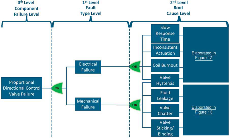
Figure 11 FTA of proportional directional control valve.
Figures 11, 12 and Figure 13 show the FTA for the hydraulic proportional directional control valve. Most of the FTA is similar to that of the ON-OFF solenoid valve except for valve hysteresis. It starts from the component level failure which is shown as at the () level. Because of the electro-mechanical linkage in the proportional valve, the failures are classified as mechanical failure and electrical failure at the () level after the FTA. At () level, the effects due to mechanical and electrical failures are shown. Most of these effects are not directly measurable but can be estimated using high-fidelity physics-based models or through effects at the system level shown by other available sensors similar to the solenoid valve explained in 4.1. From () level the root causes of the effects are elaborated till () level. It is also observed that some of the effects have multiple root causes when the FTA is moved to a deeper-rooted level.
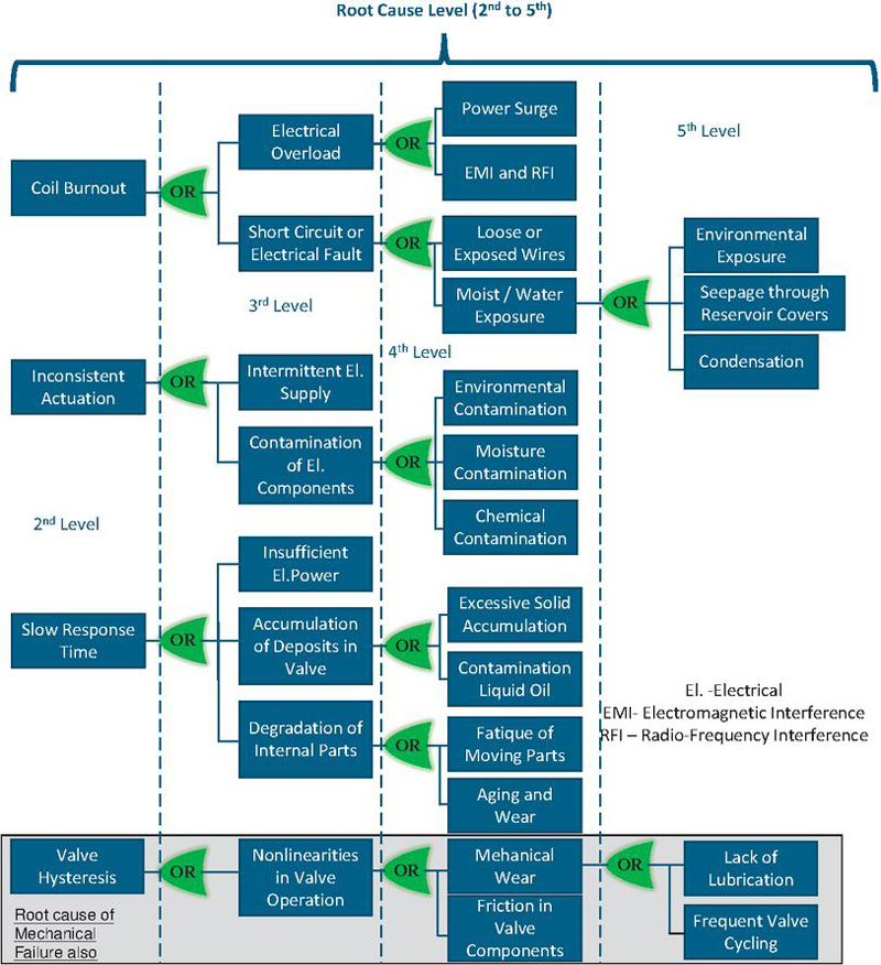
Figure 12 FTA extended from 2nd to 5th Level of Root causes for electrical failures in proportional directional control valve.
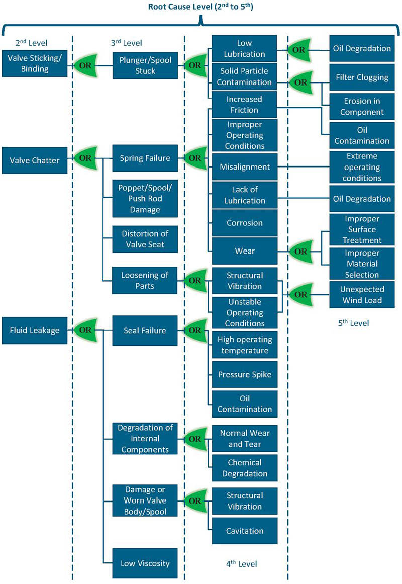
Figure 13 FTA extended from 2nd to 5th level of root causes for mechanical failures in proportional directional control valve.
4.3 Hydraulic Cylinders
The hydraulic pitch system of wind turbines utilizes hydraulic cylinders as actuators to control the pitch angle of the turbine blades. Cylinder faults in hydraulic pitch systems can lead to reduced energy conversion efficiency and reliability, but just as severely it may affect the up-time of the turbine, as faults may lead to inability to shut down the turbine because of failure in aerodynamic braking action provided by blades at pitch angle of 90∘. Research in fault detection algorithms for wind turbine pitch actuators has been conducted to address the issues. This section discusses the various faults occurring in the hydraulic cylinder along with the fault detection and condition monitoring algorithms that have been considered in the literature. In the end, the gist of the available literature is used for constructing the Fault Tree of the cylinder, which is discussed in the later part of this section. Figure 14 shows the sectional view of the hydraulic cylinder with labeling of its main parts, the linear position sensor shown here is optional in most hydraulic cylinders.
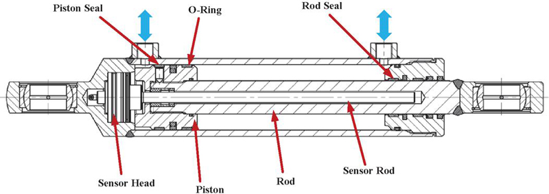
Figure 14 Hydraulic cylinder pictorial view.
Habibi et al. [49] developed a fault-tolerant constrained control solution for handling arbitrary initial conditions for wind turbine pitch actuator regulation, aiming to improve energy conversion efficiency and reliability. The paper addressed how variations in the operating conditions affect the pitch actuator dynamics [50, 51, 52], leading to ineffective power management while excluding the effect of blade aerodynamic profile change. The article’s primary effort created fault-tolerant control for pitch systems that had pitch actuator mechanism faults. Nonetheless, this article’s primary goal is to go over the effects of pitch actuator defects. Mathematically, the faults in the pitch actuator dynamics were introduced with the change in damping ratio and natural eigenfrequency along with the bias and gain for error and loss in the contol effectiveness of the pitch actuator, which leads to the system to be uncontrollable by pitch. The reasons for the actuator dynamic response change discussed in the article are high air content in hydraulic oil, hydraulic leakage, and pump wear, which leads to a change in dynamic characteristics of flow and pressure due to leakage in the pumps.
While there has been limited research on cylinder faults in wind turbines, research on cylinder faults have extended to a long range of other areas. Therefore in the following, focus will be on methods for identifying hydraulic faults in other areas and/or in a more general context, including the several kinds of cylinder failure modes.
The hydraulic cylinder failures in hydraulic press machines were studied, and fault identification techniques using the vibration sensors in existing machine set-ups were also developed by Zhe et al. [53]. A machine learning-based failure diagnostic system based on the Gaussian Process Regression model with its suitability for detecting faults for intermittent hydraulic press operation was implemented. The decrease in oil pressure in the hydraulic press due to oil leaks in cylinders was focused on failure. A model based on standard deviation, crest factor, and maximum signal values for normal operation was established, utilizing deviations and temporal changes to detect failures and anomalies. Consequently, the feasibility of predicting failures by monitoring these variations was demonstrated. However, the results were not compared quantitatively for each learning method.
A novel method was proposed by Jose et al. [54] to detect and classify cross-port leakage severity in a hydraulic excavator’s boom actuator, and the method also applies to similar machines. The pressure and boom angle sensors were used for the leakage fault prediction and early detection, aimed to prevent further damage. A total of 27 features were extracted from these two sensors and were categorized into five categories. The Binary Particle Swarm Optimization (BPSO) method was implemented to find the most effective features for fault prediction and for training an SVM classifier. This achieved a maximum classification accuracy of 97.5 %. However, the applicability of the algorithm was not verified for the different load profiles to prove its robustness.
A particle filter-based quantitative fault diagnostics method was proposed by Zhang et al. [55] for hydraulic cylinders and validated within a stochastic framework. The authors discussed the common faults in hydraulic cylinders, i.e., excessive friction and internal and external leakage. The main contributors to the mentioned faults are wear and tear of seals, temperature fluctuations, and fluid degradation [56, 57, 58, 59, 60]. The authors also critically commented on the drawbacks of using machine learning algorithms for fault classification. The authors discussed the accuracy of matching training data derived from injecting artificial faults with real-world scenarios is a subject of debate. While physics-based methods are effective in fault detection, however, they encounter difficulties when it comes to fault diagnosis. To overcome these challenges, the authors developed a particle filter-based quantitative fault diagnostics technique through carefully designed experiments. The main focus of the work was on the estimation of time-varying parameters, i.e., friction and internal and external leakage coefficients. These parameters relate to the degree of health of the cylinder. The particle filter method shown in the article demonstrated consistent accuracy exceeding 91%, even under diverse operational conditions for estimation of the time-varying parameters as discussed. The obtained results provide reliable state-parameter estimations, positioning the method as highly suitable for condition-based maintenance of hydraulic cylinders.
In the work done by Wang et al. [61], the hydraulic cylinders used in a cable pendulum bar in a space launch tower show the internal leakage identification through wavelet analysis and the back-propagation (BP) algorithm. The internal leakage fault was emulated using a throttle valve that had been added parallel to the cylinder inlet and outlet ports. Wavelet analysis was applied to the segment of the pressure sensor’s signal. The various features of the inlet pressure signal like mean value, root mean square, skewness, and kurtosis of the wavelet coefficient served as inputs for an employed BP neural network, accurately diagnosing non-leakage, small leakage, medium leakage, and large leakage in the hydraulic cylinder. The experimental results showed that the proposed method accurately identified the leakage patterns and provided quantitative results. However, the algorithm is specifically trained for an application with predetermined load cycles, making it tailored to that particular use case. Also, the approach of inducing a fault using a throttle valve appears ineffective in simulating the fault, as the throttle valve exhibits stable flow characteristics that must be met before a consistent leakage can be generated.
An overview of current fault detection methods for hydraulic and pneumatic cylinders is given in Table 6, which also includes information on the kind of cylinder, the signal used, fault identification algorithms, methods of implementation, and online applicability. For more information, see the references provided for each source. To find internal and external leaks, excessive friction, and other problems in hydraulic cylinders, researchers have used a variety of techniques, including vibration analysis, pressure, angle, and position monitoring. The accuracy numbers listed in the table are unique to the corresponding research and could change depending on the settings and setup of the experiment. A variety of techniques, including Principal Component Analysis (PCA), Convolutional Neural Network (CNN), Particle Filter, Wavelet Transform (WT), Principal Component Regression (PCR), and others, have been used by researchers for efficient fault identification. The algorithms based upon machine learning first start with the feature extraction from the standard available sensors in hydraulic systems, and later faults and their levels are classified using trained Machine Learning (ML)-based classifiers, which are mostly done in the post-processing stage. However, once the ML is trained based on all operating scenarios then it can be deployed on real-time applications.
Table 6 Recent Fault Identification Techniques and Signal Used for Hydraulic Cylinder
| Type of Cylinder (Signal) | Type of Fault | Fault Identification Algorithms | Implementation & Test Conditions | Computational Complexity & Sampling Frequency |
| Hydraulic (Vibration) | Internal Leakage | FDA= Gaussian Process Regression (GPR) FS = Support Vector Machine (SVM) |
Stage 1 Lab experiment under controlled environment [53] | High & High |
| Hydraulic (Pressure & Angle (Position)) | Internal Leakage | FE= BPSO FS = SVM Accuracy = 97.5% |
Stage 1 Lab experiment under controlled environment [54] | High & NM |
| Hydraulic (Pressure & Position from SimScape Model) | Internal & External Leakage Excessive Friction | FDA= Particle Filter Accuracy = 91 % |
Online Lab experiment under controlled environment [55] | Medium & NM |
| Hydraulic (Pressure) | Internal Leakage | FE = Wavelet Transform FS= BP Neural Network |
Stage 1 Lab experiment under controlled environment [61] | High & NM |
| Hydraulic (Pressure) | Internal Leakage | FE= Wavelet Transform FDA = Principal Component Analysis Accuracy = 99.25 % |
Stage 1 Lab experiment under controlled environment [62] | High & High |
| Hydraulic (Pressure) | Internal Leakage | FE= Wavelet Transform FS = SVM Accuracy = 97.5 % |
Stage 1 Lab experiment under Real environment Condition [63] | High & High |
| Hydraulic (Multiple Sensors) | Internal Leakage | FE& FS= CNN Accuracy = 99.8 % |
Stage 1 Lab experiment under controlled environment [64] | High & Low |
| Hydraulic (Acoustic Sensor) | Fracture Failure | FE= FEM Accuracy = NM |
Stage 1 Lab experiment under controlled environment [65] | Low & Low |
| Hydraulic (Pressure Sensor) | Internal Leakage | FE= Wavelet
Transform (WT) Accuracy = 80 % |
Stage 1 Lab experiment under controlled environment [66] | High & Medium |
| Hydraulic (Pressure) | Internal Leakage | FE= EEMD & DWT FS= HHT Accuracy = NM |
Stage 1 Lab experiment under controlled environment [67] | High & Medium |
| Pneumatic (Flow-rate & Pressure) | Internal Leakage | FE= SAE FS= SVM Accuracy = 91-100 % |
Stage 1 Lab experiment under controlled environment [68] | High & Low |
* FE = Feature Extraction, FDA = Fault Detection Algorithm, FS = Feature Selection, NM = Not Mentioned, Multiple Sensor = Refer at the text of particular reference
Table 7 presents the accuracy of various fault identification techniques employed in different studies for hydraulic cylinders.
Table 7 Accuracy of the Different Fault Identification Techniques in Different Works for Hydraulic Cylinders
| Diagnosis Method | Diagnosis Accuracy | Reference |
| Support Vector Machine (SVM) | 97.5% | Jose et al. [54] |
| Wavelet packet transform (WPT) | 91% | Qiu et al. [62] |
| WPT-SVM | 97.5% | Ma et al. [63] |
| Particle Filter | 91% | Zhang et al. [55] |
| Back-Propagation Neural Network (BPNN) | 89.09% | Wang et al. [61] |
| Convolutional Neural Network (CNN) | 99.8% | He et al. [64] |
A method for diagnosing hydraulic cylinder seal wear and internal leakage faults was proposed by Qiu et al. [62] to understand internal leakage mechanisms. The computational flow dynamics (CFD) simulation was done to study the flow field inside the internal leakage areas of the cylinder. In response to the practical limitations of employing throttle valves for simulating leakage faults, the authors introduced a more realistic approach by creating triangular microchannels, with dimensions of 1 mm and 2 mm, to better emulate the occurrence of leaks. The oil leakage was shown by extracting energy features like energy variance, and energy entropy from pressure signals using wavelet packet transform and constructing fused energy statistics for diagnosis. Comparative evaluations with seven classification algorithms demonstrated the method’s effectiveness in fault classification, even with small samples. The results indicated superior fault diagnostic accuracy compared to other algorithms, offering a novel approach for addressing piston seal wear and internal leakage in hydraulic cylinders. However, the CFD model developed in the article was used for creating a theoretical background for the selection of pressure signal features for fault diagnosis, but the model was not validated with experiments.
Ding et al. [65] examined early weld joint failure in a lightweight loader hydraulic cylinder design to determine where the structural design experienced excessive stress. To improve the end cap structure and lower the amount of stress at the weld seam, finite element methods were applied. Large spherical inclusions were shown to be the cause of fatigue fractures, and the study suggested using welding materials with a reduced amount of carbon and clearing interlayer slag carefully to reduce the production of carbide. The hydraulic cylinder’s fatigue life was increased by the redesigned structure, as demonstrated by finite element simulations. The authors of the paper examined how an engineering defect caused the hydraulic cylinder to fail and provided a rationale for using FEM to improve the cylinders’ designs after failure.
The development of a hardware-in-the-loop (HIL) simulator environment for researching fault-tolerant control and monitoring of conditions in fluid power actuation systems has been outlined in Karpenko and Sepehri [69]. The common faults such as cylinder piston leakage, changes in the bulk modulus due to air/water contamination, rod seal leakage, hydraulic pump leakage, low supply pressure, filter blockage, and increased viscous friction were discussed [70]. Using a hydraulic test bench, the simulator replicated common failure modes, facilitating real-time testing under aerospace-like conditions. The HIL experiments demonstrated the simulator’s functionality and its relevance for developing and testing fault-tolerant control and condition monitoring schemes in fluid power actuators, emphasizing the potential impacts of flight actuator failures on aircraft performance. However, the paper may not address the integration of the HIL simulator with modern technologies such as artificial intelligence, machine learning, or advanced data analytics, which could enhance fault detection and diagnosis capabilities.
An Acoustic Emission (AE) technique was utilized by Zhang et al. [56] for hydraulic cylinder internal leakage analysis. Original AE signals were decomposed using complete ensemble empirical mode decomposition with adaptive noise (CEEMDAN), distinguishing leakage levels through the first intrinsic mode function (IMF1) component analysis. However, the linkage of the change of leakage values with the pressure is not included in the algorithm development technique.
Goharrizi and Sepehri [66] presented the first application of the Wavelet Transform (WT) method for detecting and quantifying internal leakage faults in hydraulic actuators. Pressure in one actuator chamber provided a reliable signal source for diagnosis. Using Daubechies eight wavelet, the method demonstrated effective detection of internal leakages as low as 0.124 L/min in average, with corresponding level-two detail coefficients falling below the threshold value 80 % of the time. The rms values decreased with the severity of leakage, enabling more readily detection of severe leakages. In continuation of the work, the authors published another work on leakage fault identification as [67] introduced the application of the Hilbert-Huang Transform (HHT) to detect internal leakage faults in valve-controlled hydraulic actuators. The increase in the hydraulic cylinder damping was observed for the increase in the leakage of the cylinder. This affects the pressure signal transient response. Hence, the pressure signals were utilized for the extraction of the Intrinsic Mode Functions (IMFs) using EEMD analysis. After applying the Hilbert Transform (HT), the instantaneous frequencies and amplitudes were obtained from the IMFs from the healthy cylinder and the cylinder with leakage fault. It was also observed that IMF1, which contains the high-frequency component of the decomposed signal, contains the most noticeable effect due to leakage in terms of a decrease in the instantaneous amplitude. Also, the root mean square value of the instantaneous amplitude obtained from the EEMD and HHT was calculated and it was decreased with the increase in the leakage. The effectiveness of the algorithm, validated on a fully instrumented test rig, demonstrated sensitivity to internal leakage as low as 0.124 L/min. The HHT-based technique and discrete wavelet transform (DWT), are equally capable of identifying the leakage while the latter was more computer-intensive. Additionally, the article assessed the effectiveness of the algorithms for leakage detection in situations of increased friction, demonstrating that DWT leakage detection was more resistant to variations in friction qualities than HHT. The work was intended for a flight actuator application, but for wind turbines, the operating characteristics are different due to turbulence in the wind. Hence the effectiveness of the algorithms cannot be generalized.
The Wavelet Packet Transform-Support Vector Machine (WPT-SVM) method, proposed by Ma et al. [63], diagnoses faults in the wing lifting and lowering hydraulic system. Validated against an actual Very Large Crude Carrier (VLCC) hydraulic system. Six leakage fault modes were classified using an SVM-based multi-classification model to effectively identify leakage faults. Before the SVM multi-classification, the model of the wing hydraulic system was validated, and different fault modes were added to the model. The simulation involved introducing six different leakage clearances in the Electro-hydraulic reversing valve to simulate a leakage scenario. The study then demonstrated how these clearances affected the pressure signals in the piston side chamber of the hydraulic cylinder. Similarly, the six different fault modes were simulated by varying the leakage clearance in the hydraulic cylinder. The internal leakage in the hydraulic cylinder showed the effect on both the piston and rod side chambers of the hydraulic cylinder. Hence, pressure signals were selected for feature extraction using the Wavelet Packet Transform (WPT). The features were sub-band energy levels which were named wavelet packet energy, packet entropy, and energy variance. As mentioned before, the features were tagged and classified using the SVM for both piston- and rod-side chambers of hydraulic cylinders. The method showed an effectiveness of 97.5%. However, the system targeted in the study had a well-defined duty cycle as compared to what was experienced in wind turbines.
Leakage faults in two parallel-installed pneumatic cylinders were detected and diagnosed by Zhu et al. [68] using diverse signals and machine learning methods. While pneumatic cylinders and hydraulic cylinders differ in their working pressures and load capacities, algorithms designed for pneumatic systems can still be evaluated through testing on hydraulic applications. Two flow control valves with two flow sensors for each cylinder were used to simulate and measure the leakage faults. A total of eight fault levels in leakage, i.e., four in each cylinder, were created. The authors normalized the pressure signal, flow rate signals, and exergy signals of the compressed air system taken at the single upstream point. The stacked auto-encoder (SAC) algorithm was used for feature extraction and dimensional reduction from the normalized data points. Next, three classifiers namely Gaussian Process Classifier (GPC), Support Vector Machine (SVM), and k-Nearest Neighbor (KNN) were utilized to assess their performance on the three discussed datasets for categorization of faults. The exergy signal, surpassing the sensitivity of flow rate and pressure signals to system conditions, demonstrated consistent insensitivity, resulting in an average accuracy improvement ranging from 0.62% to 33.12%. The research suggested opting for the SVM classifier in comparable pneumatic system scenarios for effective and precise fault diagnosis, highlighting its superior performance and lower computational complexity in comparison to the Gaussian Process Classifier (GPC) and k-Nearest Neighbor (KNN) classifiers. However, a similar kind of approach can be adopted for the hydraulic cylinder, as shown here for pneumatic cylinders.
Na et al. [71] introduced a real-time hydraulic cylinder internal leakage fault detection method based on wavelet analysis. The pressure data of the piston side chamber were used for the development of a fault identification algorithm. The obtained experimental data revealed that wavelet analysis, not relying on precise mathematical models, offers a simpler, more cost-effective implementation, allowing real-time monitoring and performing post-processing during hydraulic cylinder operation. The experimental verification demonstrated the feasibility of the approach in practical engineering, emphasizing its significant value for detecting internal leakage faults in hydraulic cylinders. However, because of the throttle valve’s minimum flow requirement and the constant load that was simulated on the cylinders, the method of creating a fault by adding the throttle valve appears to be far from the real fault condition. Thus the algorithm’s viability needs to be examined for changing loading circumstances.
He et al. [64] proposed a method utilizing Convolutional Neural Networks (CNN) for internal leakage detection in hydraulic cylinders used in the more efficient Electro-Hydrostatic Actuators (EHA). The multi-scale CNN was obtained for extracting the features at different scales of the asserted datasets. However, if more layers in CNN are used, it may lead to gradient dispersion. This fact is also discussed by the authors. The training of the CNN involved utilizing a combination of various signals such as pressure, pressure difference, actuator speed, electric motor speed, and current consumption as datasets. The Feed-Forward Neural Network (FFNN) was also used for preparing additional datasets, i.e., pressure difference and linear position of the actuator-dependent speed of the electric motor and current of the motor, including pressure differences in the data set which yields more intrinsic information. Experimental results demonstrated a 99.8 % accuracy in detecting internal leakage under non-stationary load and velocity conditions.
Referring to Figures 15, 16 and 17, the fault tree of the hydraulic cylinder is presented. From studying the literature, it has been found that internal leakage is the most common type of fault that occurs due to seal failure in the hydraulic cylinder [72, 73, 74, 75, 76, 77, 78, 79, 80, 81, 82, 83, 84, 85, 86, 87, 88]. The article published in Machinedesign magazine [75] explains the reasons for the escalation of seal failure. It was mentioned that it starts with the hardening of seals due to exposure to high temperatures, and wear due to insufficient lubrication, improper installations can cause cuts or dents leading to scarring of the dynamic lip of the seal. Also, the fluid contamination and chemical erosion of seals leads to wear and leaks in the system. The seal wear also contributes to the increase in friction, which further reduces the performance of the actuator. This results in increased heat generation, which further reduces the seal properties and results in a vicious cycle of root causes resulting in rapid failure. The fluid contamination also contributes to the root cause of failure.
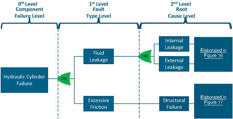
Figure 15 FTA of hydraulic cylinder.
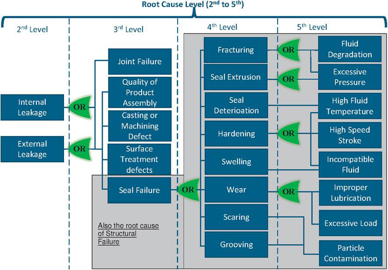
Figure 16 FTA extended from 2nd to 5th level of root causes for leakage failures in hydraulic cylinder.
Sensors such as pressure and cylinder position have played a crucial role in the hydraulic pitch system of wind turbines, contributing significantly to their performance, safety, and overall output [89, 90, 91]. However, the pitch cylinder position sensor plays a crucial role in regulating the pitch angle accurately for optimal wind energy conversion by applying a closed-loop feedback control system and also plays a pivotal role in ensuring the efficiency and reliability of the pitch control system in wind turbines. Various sensors that monitor and control the pitch angle are central to the efficient functioning of the system, ensuring safe and effective operation. However, sensor faults within the hydraulic pitch system can lead to operational disruptions, safety concerns, and decreased energy output. Understanding the nature, causes, and consequences of sensor faults is crucial for maintaining the reliability and performance of wind turbines [92].
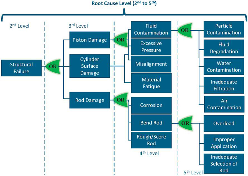
Figure 17 FTA extended from 2nd to 5th level of root causes for structural failures in hydraulic cylinder.
4.4 Sensors Used in Hydraulic Pitch System
Halder [93] conducted a simulation study to investigate the detection of sensor and process faults, characterized as parametric deviations. The study utilized an Extended Kalman Filter (EKF) in an electro-hydraulic actuator-driven flex nozzle control system. Multiple EKFs were employed to detect faults, including LVDT signal failure, pressure transducer signal failure, flex-seal stiffness fault, and bulk-modulus faults in electro-hydraulic actuation systems using OPAL-RT/RT-LAB. The EKF-based estimator accurately estimated states such as position and differential pressure, as well as physical parameters like flex-seal stiffness and bulk-modulus. The formulation of a Fault Diagnosis Matrix (D-Matrix) utilized the distinct fault patterns observed during each fault. It was found that the proposed approach was deemed suitable for continuous health monitoring of electro-hydraulic actuators in tactical aerospace vehicles, particularly concerning process or sensor faults. Youssef et al. [94] introduced a novel method for addressing the design of a Proportional Integral observer to estimate actuator and sensor faults based on a Takagi–Sugeno fuzzy model with unmeasurable premise variables. The study utilized a nonlinear model of a three-tank hydraulic system for simulation analysis. The faults were assumed to be time-varying signals with bounded time derivatives. Simulation results included the estimation of states, output, and errors for time-varying actuator and sensor faults using Lyapunov stability theory and L2 performance analysis. The Proportional Integral observer gains were computed by solving proposed conditions under Linear Matrix Inequalities constraints. The obtained simulation results demonstrated good simultaneous estimation of states, actuator, and sensor faults.
Yanqing et al. [95] developed a practical system focused on identifying faults in solenoid valves, specifically targeting the neutral function and recognizing specific faults such as limit switch and pressure sensor failures. Fault tests were conducted on a hydraulic drive platform using pressure sensor chips and limit switches. The tests involved three types of faults: output signal staying at a fixed value, output signal irregularly hopping, and output signal being under normal healthy operating conditions; across six sensing elements of one testing unit comprising nine different valve types, totaling 162 different working conditions. The experimentation aims to extract failure indications from the test data and establish a reliable fault diagnostic technique. Experimental results found that an SVM-based classifier achieved a significant classification accuracy of 95.68% across the testing cases.
Helwig et al. [96] introduced a Condition Monitoring (CM) approach to cover a wide range of detectable fault types, encompassing continuous faults related to the hydraulic system and various sensor faults of the installed sensor network. The proposed approach was developed to identify sensor faults before they arise, such as noise, signal peak, drift, or constant offset. The hydraulic experimental setup was used for training data collection of faults of components such as the main pump, valve, accumulator, and cooler. The feature extraction, selection, and supervised learning of obtained data was conducted utilizing Linear discriminant analysis (LDA) and Artificial Neural network (ANN). Comparing both both classifications the ANN classifier showed a 20% higher detection rate as compared to LDC. The sensor fault-tolerant control (SFTC) technique, as performed by Van Nguyen and Ha [97], addressed a nonlinear Electro-hydraulic actuator (EHA) system. The Mini Motion Package (MMP) system was developed, and a mathematical model for position tracking control was formulated and improved using a proportional-integral-derivative (PID) controller. To estimate states, disturbances, and sensor faults, an unknown input observer (UIO) was constructed, enabling a stable control error to be obtained through a linear matrix inequality (LMI) optimization algorithm based on Lyapunov’s stability condition. In simulations, the SFTC technique demonstrated approximately 93.78% performance of tracking position reference in the case with a disturbance and 94.91% in the case without a disturbance. It was observed that the fault and disturbance nearly canceled out utilizing the SFTC technique. In experiments with a real MMP system, the average performance obtained 59.82% when employing the SFTC technique. With the SFTC technique, the average performance increased by 65.51% (from 5.69 % to 59.82%), which minimizes the faults and disturbances and improves the stability of the system. Li et al. [98] proposed the Kalman filter, combined with fiber Bragg grating (FBG) sensors, to detect faults in the hydraulic pipeline system. By causing pipeline collisions and clamp loosening, real-time experiments were carried out to validate the suggested method for locating hydraulic pipeline system problems. For obtaining the pipeline vibration signal, a low-dimensional autoregressive (AR) model was developed, and the Kalman filter technique was applied to estimate the state of the pipeline system. The obtained results showed that FBG sensors, with high precision in detecting fault vibration signals, outperformed acceleration sensors. The Kalman filter exhibited strong sensitivity, proving effective for fault detection and maintenance in hydraulic systems. A novel Active Fault-Tolerant Control (AFTC) was introduced by Mazare et al. [99] for wind turbine pitch angle control. The faults considered include bias and gain degradation faults of Pitch sensor faults as well as pump wear, hydraulic leakage, and high air content in the oil faults of Pitch actuator faults. The approach incorporates time delay estimation (TDE) for fault detection and a combination of back-stepping, terminal sliding mode (TBSM), and adaptive fractional-order control for increased robustness. For stability analysis Lyapunov theory was implemented and for the effectiveness of proposed method the aero-elastic wind turbine simulator FAST simulator was used in faulty and healthy conditions. Using AFTC the obtained effectiveness for rotor speed as measured by the fit function, given by Equation (1), between estimated and actual rotor speed was 96.34%.
| (1) |
The proposed method shows advantages such as easy TDE-based Fault Detection (FD) implementation, fast finite-time convergence, and precision with the super-twisting algorithm. It furthermore exhibited fault and uncertainty compensation, along with independence from prior fault knowledge. Phan and Ahn [100] introduced advanced fault tolerant control (FTC) to the electro-hydraulic servo system (EHSS) dynamics model, effectively overcoming negative influences like disturbance, uncertainties, and multiple sensor faults. Three Nonlinear Unknown Input Observers (NUIO) were deployed for simultaneous detection and estimation of sensor faults, successfully identifying and isolating position, velocity, or load pressure sensor faults. The advanced FTC scheme, comprising Dynamic surface control (DSC), NUIO, and Extended State Observers (ESO), provided continuous tracking control regardless of sensor faults and disturbances, with stability and asymptotic tracking convergence verified by the Lyapunov theory. The simulation studied performed the proposed method using MATLAB to evaluate performance under the influence of sensor fault and lumped uncertainties. The Simulation results obtained from comparison studies demonstrated the effectiveness of the proposed algorithm. Table 8 summarizes recent fault identification techniques for hydraulic sensors in various components.
Table 8 Recent Fault Identification Techniques and Signal Used for Hydraulic Sensor
| Experimented Componenet | Sensors Type | Fault Identification Algorithms | Implementation & Test Conditions | Computational Complexity & Sampling Frequency |
| Solenoid Valve | Limit Switch Pressure Sensor | FE = average change value FS = Support Vector Machine (SVM) Accuracy = 95.68% |
Stage 1 Lab experiment under controlled environment [95] | High & High |
| Hydraulic Cylinder | Linear variable differential transformer (LVDT) | FDA=Unknown Input Observer (UIO) Accuracy = NA |
Stage 1 Lab experiment under controlled environment [97] | Medium & Not Provided |
| Hydraulic Pipeline | FBG sensors accelerometer | FDA = Kalman Filter (KF) Fiber Bragg Grating (FBG) Accuracy = NA |
Stage 1 Lab experiment under controlled environment [98] | Medium & High |
* FE = Feature Extraction, FDA = Fault Detection Algorithm, FS = Feature Selection, NM=Not Mentioned
Deep learning-based condition monitoring was also applied by König and Helmi [101] to a multi-sensor dataset of a hydraulic installation. 1D convolutional neural networks (CNN) were designed to capture the temporal evolution of the sensor signal without explicit feature engineering. In this work, the general hydraulic test bench was considered for creating the dataset by emulating the faults in the major components using the auxiliary components. Various faults like internal pump leakage, pressure drop in the accumulator, valve delay, and reduced cooler efficiency has been studied for monitoring the fault effects on the components. The study focused on key components of the hydraulic circuit, including the pump, accumulator, electric motor, unloading solenoid valve, pressure relief valve, check valve, and a flow control valve with an on-off solenoid. Additionally, four accumulators, each charged at different pre-charge pressures and equipped with on-off solenoid valves, were analyzed. Sensor components were used to monitor system performance, while potential hydraulic system faults considered included cooler efficiency degradation, valve switching degradation, internal pump leakage, and gas leakage in the hydraulic accumulator.
The system demonstrated high accuracy in proper fault characterization, and a misclassification analysis was conducted. The study focused on CNN model interpretability, optimizing the number of sensors through attribution analysis and reducing the feature set without compromising accuracy. After experimentation, the cooler variable achieved an overall classification accuracy of 99.6 % and a Mathews Correlation Coefficient (MCC) of 0.992. To clarify the difference between classification accuracy and Mathews Correlation Coefficient (MCC), the later is a more robust and balanced metric when it comes to the imbalanced datasets than the former. Accuracy only considers the total correct predictions, so it can be inflated by the majority class, while MCC considers the balance between true and false predictions for both classes, giving a more nuanced and reliable evaluation of the model’s performance. So for more awareness among the readers, the benefit of writing about MCC in binary classification problems can be useful. The valve variable achieved an accuracy of one and an MCC of one, while the internal pump leakage variable achieved an accuracy of 97% and an MCC of 0.91. Additionally, the hydraulic accumulator obtained an accuracy of 98.2% and an MCC of 0.947. The obtained results show the potential of attribution analysis for feature selection in designing condition monitoring systems. A two-staged Fault Detection and Diagnosis (FDD) approach was proposed by Mallak and Fathi [102] utilizing a Long Short-Term Memory (LSTM) autoencoder for fault detection and a subsequent classification process for fault diagnosis. The proposed method was applied in experiments involving different fault types, sensor faults, and component faults. After experimentation, the sensor fault detection found 62% signal difference accuracy, and applying LSTM autoencoder, the accuracy was observed as 71%, where the signal difference accuracy was calculated by taking the amplitude of the difference of two time series.
For the component fault detection signal difference accuracy observed as 69% and using proposed as 71%. In another experiment, the time-domain extracted features along with CART and LSTM classifiers for sensor fault were found with diagnosis accuracies of 99.51% and 96.84%. Finally, for the components fault with all multi-variant features, Feature Importance (FI) combined with an all ML classifier showed extremely high accuracies exceeding 98%. The obtained experimental data demonstrated superior detection accuracy and highlighted the significance of tailored feature engineering in the diagnosis phase. The obtained results indicated a reduction in time and computational complexities. [103] describes a knowledge-based system designed to detect and mitigate sensor faults in a ball-screw electro-mechanical actuator system connected mechanically to a hydraulic load cylinder for loading. The system employs an expert system approach to model and diagnose sensor faults such as bias, drift, scaling, and dropout, as well as system faults. Sensor value correction is utilized to compensate for faulty sensors, with control and data acquisition performed by real-time software running on a dSPACE platform. Vibration in the Z-direction is measured using an accelerometer, temperature is measured by a T-type thermocouple, and LVDT, load cell, and current transducers are also employed for fault diagnosis. The obtained results using KB approaches demonstrate comparable performance with a deployed Neural Network-based system but with expanded capabilities and flexibility for handling different fault scenarios. A Sensor Fault Estimation (FE) scheme developed by Djordjevic et al. [104] for uncertain Lipschitz nonlinear systems addresses hydraulic servo actuators. The scheme involves transforming the original system into two subsystems, effectively addressing system uncertainties and sensor faults separately. A Sliding Mode Observer (SMO) approach utilized to rationalize the FE and make the system more robust. The impact of system uncertainties on the estimation errors of states and faults is minimized by integrating an H uncertainty attenuation level into the observer’s linear matrix inequality (LMI) optimization. The obtained simulation results confirm the scheme’s effectiveness in the presence of uncertainties, demonstrating its applicability and feasibility for hydraulic systems. A fault diagnosis method for detecting sensor faults in electro-hydraulic actuators proposed by Li et al. [105]. The method utilizes quantum particle swarm optimization (QPSO) and least square support vector regression (LSSVR) algorithm to forecast sensor output and indicate faults based on residual calculation. QPSO is employed to optimize hyper-parameters for improved prediction accuracy. Simulation experiments show that QPSO-LSSVR outperforms PSO-LSSVR in terms of prediction error and convergence rate. The method is effective in detecting typical sensor faults in actuator systems. The obtained simulation results demonstrated the feasibility and improved performance of the proposed sensor fault diagnosis method.
An extensive literature review indicates that cylinder position and pressure transducers are predominantly utilized, thereby contributing to a higher rate of failure. Moreover, temperature sensors, accelerometers, load cells, and current transducers are also employed to assess the functionality of hydraulic systems. The fault tree for the hydraulic sensors employed in the hydraulic pitch system is illustrated in Figures 18 and 19. This presents a general overview of the failure that can occur in the sensors used in hydraulic systems. It provides a comprehensive overview of the primary root causes and the impact of these factors on the failure of hydraulic sensors.
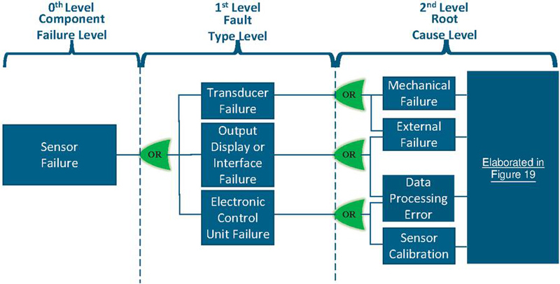
Figure 18 FTA of sensors used in hydraulic pitch system.
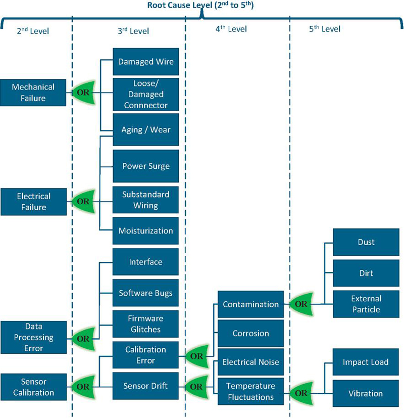
Figure 19 FTA for hydraulic sensors from 2nd to 5th level.
5 Discussion
This article focuses on fault tree analysis of four key components of the hydraulic pitch system, with the primary objective of identifying the major faults that occur within these components. However, the study goes beyond the identification of faults by delving into their root causes at a deeper level. This approach provides stakeholders with a detailed understanding of the issues and allows them to address the failure in the components systematically. In addition to examining faults in components, the literature also emphasizes the algorithms used to identify these faults, specifically at the component level as shown in Tables 2, 4, 6 and 8.
Most of the literature studied shows that the machine learning algorithms applied to historical data-sets are used to develop pre-trained models. Data for training for machine learning models have been collected by inducing faults in components to speed up the data collection process at different failure modes. Most of the data gathered are done at laboratory scale experiments with known load profiles. Various types of sensors such as vibration, acoustic, current, voltage and temperature, which are not currently used in standard pitch systems, were used at high sampling frequencies that may either not be possible with the current standard PLCs used in hydraulic pitch system. However, it has not been evident that feature extraction algorithms will not identify critical features based on low sampling frequency as used by current PLC systems for data processing and logging. More focus on advanced feature extraction algorithms that may work with lower sampling frequencies may, therefore, be of interest. This could e.g. relate to faults like wear inside components leading to internal fluid leakage, as these are slower in development and therefore may be monitored with slow sampling frequency signals captured by the data logging sampling in hand.
Table 9 shows the complexities of various ML algorithms are represented using Big O notation to provide some rational about implementing these algorithms for fault-detection in soft or hard real-time. However, its very difficult to analyze ML algorithms using Big O notation alone due to its non-deterministic nature, data dependency and algorithm variants. Based upon computational complexity the algorithms, such as, SVM and Random Forests can be deployed in real-time after training, provided the standard PLC hardware is upgraded to PC-level capabilities. However, the inference of these ML algorithms also requires higher computational resources due to the complexity of feature extraction and processing. On the other hand, model-based approaches like the Extended Kalman Filter (EKF) and Particle Filter can be implemented online the existing system using a known model of the system. However, these methods may require control loops with higher sampling frequencies, around 1 kHz, which could exceed the capabilities of standard PLC systems.
Table 9 Algorithms and Recommendations for Online Implementation
| Algorithm | Why It Is Suitable | Big O Notation (Complexity) [106] | Recommendation |
| Solenoid Valve | |||
| FE = WPD & PCA, FDA = C-SVM | Robust for classification with small to medium-sized datasets; High training overhead, but lightweight for inference after training [17] | FE = O() FDA Training = O() Inference = O() |
Use SVMs if pre-trained offline; load the model for real-time predictions |
| FE = PCA, FDA = XG Boost | Robust for classification with small to medium-sized datasets; High training overhead, but lightweight for inference after training [18] | FE = O() : no. of features FDA Training = O(...) Inference = O(.) : no. of trees : no. of training samples : no. of features |
Use SVMs if pre-trained offline; load the model for real-time predictions |
| FE = EEMD & TEO FS = FRSSD & mRMR FDA = CNN |
Decomposes complex signals into intrinsic mode functions; Adept at capturing instantaneous energy variations in signals; Selects features that maximize class separability [19] | FE = O(..) for EEMD O() for TEO : no. of ensemble size FS = O() FDA Training = O(...) Inference = O(..) |
For online implementation requires significant computational resources and efficient algorithms to process data in real-time. |
| FDA= CAE Hypersphere Based Classification | Classification offers a robust framework for fault diagnosis in hydraulic solenoid valves effectively handling both known and unknown fault types [20] | Training = O(...+.) Inference = O(.+.) | Heavily relies on high-quality labeled data for training; For Implementing online computational efficiency must be optimized |
| FE = Wavelet FDA = Diagnostic Decision and Comparison with healthy state |
Effectively captures non-stationary signal features, identifies deviations from normal operation, and enables real-time monitoring [21] | FE = O(.) FDA = O(.) |
Online implementation is preferable for immediate fault diagnosis, while offline use can support in-depth failure analysis |
| FDA = Dempster-Shafer Fusion Theory (DSmT) | Robust, reliable fault diagnosis by fusing uncertain and noisy data from multiple sources in real-time [22] | Training = O(.(..)+.. +..+) Inference = O(..+.. +..+) | Handle noisy or uncertain data makes it suitable for online deployment in industrial environments, where real-time decision-making is critical |
| Proportional Valve | |||
| FE = Wavelet Transform FDA= GOA-SVM |
Complementary strengths in analyzing complex signals and Optimizing classification performance [40] | FE = O(.) FDA Training = O(..) Inference = O(.) |
Can be computationally intensive, potentially limiting real-time application feasibility; Overfitting Risk |
Table 10 Algorithms and Recommendations for Online Implementation
| Algorithm | Why It Is Suitable | Big O Notation (Complexity) Comparison | Recommendation |
| FDA = Random Forests | Handle both classification and regression tasks; Robustness against overfitting, and Ability to handle complex data [47] | FDA Training = O(.+..) Inference = O(+.) | Need high computational resources for model training and once trained the model can be implemented for online inference. |
| Hydraulic Cylinder | |||
| FDA= Gaussian Process Regression (GPR) FS = Support Vector Machine (SVM) |
Captures uncertainty and variability in signals; Resistant to overfitting, especially in high-dimensional spaces.[53] | FDA Training = O(.) FS Training = O() Inference = O(.+) |
Needs a well-labeled, diverse dataset for training. |
| FE= BPSO FS = SVM |
High detection accuracy; robust to various operating conditions; effectively optimizes the feature selection process and enhancing the performance [54] | FE = O(...) FS Training = O(.) Inference = O() + O() |
For online use, ensure strong computing power and a stable network. For offline use, focus on reliable data storage and management. |
| FE= Wavelet Transform FS = BPNN |
Highly effective in decomposing signals into different frequency components; improving performance over time as more data becomes available[61] | FE = O() FS Training = O(..) Inference = O(.) |
Can be used online if optimized, but better suited for offline analysis; Consider lightweight ML models or simpler transforms for real-time applications |
| FE & FS= CNN | Effectively reduce noise and fully extract features [64] | FE Training = O(....) Inference = O(...) | Risk of overfitting; requiring powerful hardware and significant time |
| FE= EEMD & DWT FS= HHT |
Decomposes complex signals into simpler components IMFs; reduce noise; provides instantaneous frequency information [67] | O(.) | EEMD may struggle with very short signals;HHT may require significant processing power for real-time applications |
| Hydraulic Sensor | |||
| FS = Support Vector Machine (SVM) | High Accuracy; Effective Hyperparameter Tuning; Robustness to Overfitting ;Avoidance of Additional Testing Equipment [95] | FE = O() FDA Training = O() Inference = O() |
Continuously optimize hyperparameters; Enhance feature extraction process; Periodically retrain model; Integration with Monitoring Systems |
* = no. of training samples, = no. of trees, = no. of features, = no. of ensemble size, = no. of epochs, = no. of kernels, = length of kernel, = no. of channels, = no. of fault types, = depth of the wavelet transform , = sequence length for LSTM, = no. of layers, = No. of convolutional layers, = Population size in swarm, = no. of generation, = no. of Neurons in the layer
The machine learning models discussed in this article are initially trained offline due to their high computational demands. However, some of these algorithms are capable of running online and suggested algorithms are reported in the tables formulated in each section related to the component type. These algorithms can potentially be modified and tested at first place according to the requirements of pitch system. With the evaluation of performance of these algorithms the hardware can be upgrade. Upgrading the PC-based hardware capabilities may increase the cost allocation for the pitch system. However, this can be offset by integrating it with other subsystems of the turbine, potentially reducing the overall cost share for the pitch system.
As mentioned earlier, the algorithms are tested under controlled laboratory conditions and trained on historical data sets which may lead to the false alarms or warnings if implemented on the real environment conditions. To cater this challenge, the modification in the test runs procedure during start-up operation and recording of signals can be done and algorithms can run offline to predict faults in the system or component level. These strategies while keeping in mind holistic approach helps the system engineers to enhance reliability and schedule maintenance of systems.
Regarding FTAs, the process was carried out in close collaboration with wind turbine stakeholders to ensure its relevance and accuracy. The FTA has been specifically developed for critical components used in wind turbines, considering their unique operational conditions and failure modes. Additionally, the construction of the FTA is grounded in an extensive review of existing literature on faults and failures associated with these components. Regarding failure rate occurrence, some analysis have been made in this regard, but the data is bound by confidentiality and can therefore not be disclosed. The failure modes in the FTA do, however, represent failure modes seen in data, although the occurrence rate is not reflected.
6 Conclusion
The focus of the current study has been to identify and map the failures in hydraulic pitch systems and the main components based on state-of-the-art failure mode knowledge and detection methods. The current paper is the first part of this study and addresses four major component groups within the hydraulic pitch system, being: hydraulic cylinders, on-off solenoid valves, proportional valves, and sensors. These components are specifically targeted for analysis, emphasizing their critical roles in system operation and failure potential.
Hydraulic cylinders serve as an integrated part of the pitch system, allowing the adjustment of the blade angles to optimize the performance of the turbine. On-off solenoid valves control the flow of hydraulic fluid, regulating the operation of various system functions. Proportional valves offer precise control over fluid flow rates, enabling fine adjustments to blade positions based on changing environmental conditions. Additionally, sensors provide essential feedback on system parameters such as pressure, temperature, and position, facilitating monitoring and control.
By focusing on these key components, the study aims to provide a comprehensive understanding of failure modes and root causes within the hydraulic pitch system. Through Fault Tree Analysis (FTA), Failure Mode Effect Analysis (FMEA) methods, and other analytical techniques, maintenance and design teams can identify critical fault factors and develop effective mitigation strategies. Furthermore, the study has shown that incorporating approaches like machine and artificial intelligence techniques has been shown to be able to enhance the fault identification process for a range of components. This is done by analyzing operational data collected from sensors and monitoring devices, machine learning algorithms can detect anomalies and deviations indicative of potential failures. This proactive approach enables maintenance teams to address issues before they escalate, minimizing downtime and optimizing system performance.
However, it is worth noting that many algorithms are tested in literature are designed based on predefined load cycles, presenting a limitation in their general applicability. Therefore, the effectiveness of these algorithms often varies depending on the specific application context. Despite this limitation, there is potential for deploying these algorithms in real-time applications such as wind turbines. Moreover, there is an opportunity to explore these algorithms for a wide range of potential applications beyond their current scope. By adapting and fine-tuning these algorithms to suit different operational conditions and environments, they could prove valuable in enhancing the reliability and performance of various systems beyond wind turbines. This exploration could lead to innovative solutions and advancements in predictive maintenance across diverse industries.
In summary, the inclusion of hydraulic cylinders, on-off solenoid valves, proportional valves, and sensors in the analysis underscores their significance in the overall operation of the hydraulic pitch system. Through a combination of analytical methods and advanced technologies, the focus of this study has hence been to identify the methods to enhance fault detection and predictive maintenance strategies, ultimately improving the reliability and efficiency of hydraulic systems across various applications.
Abbreviations
| ABC | Adaboost Classifier |
| ADLSSVM | Adaptive Dynamic Least Squares SVM |
| ALT | Acceleration Lifetime Testing |
| ANFIS | Adaptive Network-Based Fuzzy Inference System |
| AFTC | Active Fault-Tolerant Control |
| BPNN | Back-Propagation Neural Network |
| BPSO | Binary Particle Swarm Optimization |
| BP | Backpropagation |
| CAE | Convolutional Auto-Encoder |
| C-SVM | C-Parameter Support Vector Machine |
| CART | Classification and Regression Trees |
| CFD | Computational Flow Dynamics |
| CNN | Convolutional Neural Networks |
| DSmT | Dezert-Smarandache Theory |
| DRSN | Deep Residual Shrinkage Network |
| DT | Decision Tree |
| ECA | Efficient Channel Attention |
| EEMD | Ensemble Empirical Mode Decomposition |
| EKF | Extended Kalman Filter |
| EHT | Elastic Weight Consolidation |
| EHA | Electro-Hydrostatic Actuators |
| EMD | Empirical Mode Decomposition |
| EPPR | Electronic Proportional Pressure Reduction |
| EWC | Elastic Weight Consolidation |
| EWT | Empirical Wavelet Transform |
| FDA | Fault Detection Algorithm |
| FE | Feature Extraction |
| FEM | Finite Element Method |
| FMEA | Failure Mode and Effects Analysis |
| FS | Feature Selection |
| FTA | Fault Tree Analysis |
| GBC | Gradient Boosting Classifier |
| GPC | Gaussian Process Classifier |
| GPR | Gaussian Process Regression |
| GOA-SVM | Grasshopper Optimized Support Vector Machine |
| HHT | Hilbert-Huang Transform |
| HIL | Hardware-in-the-loop |
| HSVs | Hydraulic Solenoid Valves |
| IMF | Intrinsic Mode Functions |
| K-NN | K-nearest Neighbor |
| LDA | Linear Discriminant Analysis |
| LDT | Linear Displacement Transducer |
| LSSVM | Least Squares SVM |
| LSTM | Long Short-Term Memory |
| LR | Logistic Regression |
| LVDT | Linear Variable Differential Transformer |
| MCC | Matthews Correlation Coefficient |
| ML | Machine Learning |
| MLS | Machine Learning Service |
| MLP | Multi-Layer Perceptron |
| MMP | Mini Motion Package |
| NM | Not Mentioned |
| PCA | Principal Component Analysis |
| PCR | Principal Component Regression |
| QDA | Quadratic Discriminant Analysis |
| RBF | Radial Basis Function |
| RBFNN | Radial Basis Function Neural Network |
| RF | Random Forest |
| RMS | Root Mean Square |
| RUL | Remaining Useful Life |
| SAE | Stacked Auto-Encoders |
| SAEKF | State Augmented Extended Kalman Filter |
| SEWT | Sparsity Empirical Wavelet Transform |
| SFTC | Sensor Fault-Tolerant Control |
| SSL | Semi-Supervised Learning |
| SVM | Support Vector Machine |
| SVM-Lin | Linear SVM |
| SVM–RBF | Radial-Basis Function SVM |
| TEO | Teager-Kaiser Energy Operator |
| UIO | Unknown Input Observer |
| VMD | Variational Mode Decomposition |
| VLCC | Very Large Crude Carrier |
| WPD | Wavelet Packet Decomposition |
| WT | Wavelet Transformations |
Funding
This research was funded by the Danish Energiteknologisk Udviklings- og DemonstrationsProgram (EUDP) grant number 64022-1058. The authors gratefully acknowledge the funding, which made this work possible.
References
[1] Conka et al. [2022] Zsolt Conka, Lubomír Bena, Róbert Štefko, Marek Pavlík, Peter Holcsik, and Judith Pálfi. Wind turbine power control according to eu legislation. Energies, 15(22), 2022. ISSN 1996-1073. . URL https://www.mdpi.com/1996-1073/15/22/8614.
[2] Walgern et al. [2023] Julia Walgern, Katharina Fischer, Paul Hentschel, and Athanasios Kolios. Reliability of electrical and hydraulic pitch systems in wind turbines based on field-data analysis. Energy Reports, 9:3273–3281, 2023.
[3] Kocsis and Xydis [2019] Gergely Kocsis and George Xydis. Repair process analysis for wind turbines equipped with hydraulic pitch mechanism on the us market in focus of cost optimization. Applied Sciences, 9(16):3230, 2019.
[4] Skrimpas et al. [2015] Georgios Alexandros Skrimpas, Kun S Marhadi, Robert Gomez, Christian Walsted Sweeney, Bogi Bech Jensen, Nenad Mijatovic, and Joachim Holboell. Detection of pitch failures in wind turbines using environmental noise recognition techniques. In Annual Conference of the PHM Society, volume 7, 2015.
[5] Elorza et al. [2021] Iker Elorza, Iker Arrizabalaga, Aritz Zubizarreta, Héctor Martín-Aguilar, Aron Pujana-Arrese, and Carlos Calleja. A sensor data processing algorithm for wind turbine hydraulic pitch system diagnosis. Energies, 15(1):33, 2021.
[6] Korkos et al. [2022] Panagiotis Korkos, Jaakko Kleemola, Matti Linjama, and Arto Lehtovaara. Fault detection in a wind turbine hydraulic pitch system using deep autoencoder extracted features. In PHM Society European Conference, volume 7, pages 261–268, 2022.
[7] Bergstrom [2018] Leland Bergstrom. Pitch control: Critical for wind power. Machine Design, April 2018. Available online: https://www.machinedesign.com/mechanical-motion-systems/article/21836463/pitch-control-critical-for-wind-power.
[8] http://archive.ics.uci.edu/ml/datasets/Conditionmonit-oringofhydraulicsystems. [Accessed 12-12-2023].
[9] Carroll et al. [2016] James Carroll, Alasdair McDonald, and David McMillan. Failure rate, repair time and unscheduled o&m cost analysis of offshore wind turbines. Wind Energy, 19(6):1107–1119, 2016.
[10] Liniger et al. [2017] Jesper Liniger, Mohsen Soltani, Henrik C Pedersen, James Carroll, and Nariman Sepehri. Reliability based design of fluid power pitch systems for wind turbines. Wind Energy, 20(6):1097–1110, 2017.
[11] Yang et al. [2011] Xiyun Yang, Jinxia Li, Wei Liu, and Peng Guo. Petri net model and reliability evaluation for wind turbine hydraulic variable pitch systems. Energies, 4(6):978–997, 2011.
[12] Tinga [2012] Tiedo Tinga. Model-based fault analysis of a hydraulic system. https://ris.utwente.nl/ws/portalfiles/portal/5143465/MBFA_final.pdf, 2012. Accessed: 2023-11-27.
[13] Fennel AI [2025] Fennel AI. Challenges of building real-time ml pipelines, 2025. URL https://fennel.ai/blog/challenges-of-building-realtime-ml-pipelines/. Accessed: 2025-01-07.
[14] Atosolenoidvalves [2022] Atosolenoidvalves. Solenoid valve in wind turbine, 2022. URL https://www.atosolenoidvalves.com/solenoid-valve-in-wind-turbine.html. Accessed: 24/01/2024.
[15] Keba [2024] Keba. Pitch and yaw systems in wind turbine, 2024. URL https://www.keba.com/en/news/industrial-automation/pitch-and-yaw-systems-wind-turbine#:~:text=The%20pitch%20system%20regulates%20the,the%20highest%20possible%20energy%20yield. Accessed: 24/01/2024.
[16] Account Manager Roger Shelzer. Valve Chatter and How To Fix It - Global Electronic Services — gesrepair.com. https://gesrepair.com/valve-chatter-and-how-to-fix-it/. [Accessed 24-01-2024].
[17] Ma et al. [2022a] Dong Ma, Zhihao Liu, Qinhe Gao, and Tong Huang. Fault diagnosis of a solenoid valve based on multi-feature fusion. Applied Sciences, 12(12):5904, 2022a.
[18] Lei et al. [2019] Yafei Lei, Wanlu Jiang, Anqi Jiang, Yong Zhu, Hongjie Niu, and Sheng Zhang. Fault diagnosis method for hydraulic directional valves integrating pca and xgboost. Processes, 7(9):589, 2019.
[19] Shi et al. [2021] Jinchuan Shi, Jiyan Yi, Yan Ren, Yong Li, Qi Zhong, Hesheng Tang, and Leiqing Chen. Fault diagnosis in a hydraulic directional valve using a two-stage multi-sensor information fusion. Measurement, 179:109460, 2021.
[20] Yoo et al. [2023] Seungjin Yoo, Joon Ha Jung, Jai-Kyung Lee, Sang Woo Shin, and Dal Sik Jang. A convolutional autoencoder based fault diagnosis method for a hydraulic solenoid valve considering unknown faults. Sensors, 23(16):7249, 2023.
[21] Guo et al. [2016] Haifeng Guo, Kai Wang, He Cui, Aidong Xu, and Jin Jiang. A novel method of fault detection for solenoid valves based on vibration signal measurement. In 2016 IEEE International Conference on Internet of Things (iThings) and IEEE Green Computing and Communications (GreenCom) and IEEE Cyber, Physical and Social Computing (CPSCom) and IEEE Smart Data (SmartData), pages 870–873. IEEE, 2016.
[22] Ji et al. [2020] Xiancheng Ji, Yan Ren, Hesheng Tang, Chong Shi, and Jiawei Xiang. An intelligent fault diagnosis approach based on dempster-shafer theory for hydraulic valves. Measurement, 165:108129, 2020.
[23] Liniger et al. [2020] Jesper Liniger, Søren Stubkier, Mohsen Soltani, and Henrik C Pedersen. Early detection of coil failure in solenoid valves. IEEE/ASME Transactions on Mechatronics, 25(2):683–693, 2020.
[24] Moseler and Straky [2000] Olaf Moseler and Harald Straky. Fault detection of a solenoid valve for hydraulic systems in vehicles. IFAC Proceedings Volumes, 33(11):119–124, 2000.
[25] Jo et al. [2020] Soo-Ho Jo, Boseong Seo, Hyunseok Oh, Byeng D Youn, and Dongki Lee. Model-based fault detection method for coil burnout in solenoid valves subjected to dynamic thermal loading. IEEE Access, 8:70387–70400, 2020.
[26] Ji et al. [2021] Xiancheng Ji, Yan Ren, Hesheng Tang, and Jiawei Xiang. Dsmt-based three-layer method using multi-classifier to detect faults in hydraulic systems. Mechanical Systems and Signal Processing, 153:107513, 2021.
[27] Zhong et al. [2023] Qi Zhong, Enguang Xu, Yan Shi, Tiwei Jia, Yan Ren, Huayong Yang, and Yanbiao Li. Fault diagnosis of the hydraulic valve using a novel semi-supervised learning method based on multi-sensor information fusion. Mechanical Systems and Signal Processing, 189:110093, 2023.
[28] Angadi et al. [2009a] Santosh V Angadi, RL Jackson, Song-Yul Choe, GT Flowers, JC Suhling, Young-Kwon Chang, and Jung-Keol Ham. Reliability and life study of hydraulic solenoid valve. part 1: A multi-physics finite element model. Engineering Failure Analysis, 16(3):874–887, 2009a.
[29] Angadi et al. [2009b] Santosh V Angadi, RL Jackson, Song-yul Choe, GT Flowers, JC Suhling, Young-Kwon Chang, Jung-Keol Ham, and Jae-il Bae. Reliability and life study of hydraulic solenoid valve. part 2: Experimental study. Engineering Failure Analysis, 16(3):944–963, 2009b.
[30] ato [2023] Proportional directional valves for wind turbines. https://www.atos.com/en-it/Proportional-directional-valves-for-wind-turbines, 2023. Accessed: November 21, 2023.
[31] Venkaiah and Sarkar [2022] Paladugu Venkaiah and Bikash Kumar Sarkar. Electrohydraulic proportional valve-controlled vane type semi-rotary actuated wind turbine control by feedforward fractional-order feedback controller. Proceedings of the Institution of Mechanical Engineers, Part I: Journal of Systems and Control Engineering, 236(2):318–337, 2022.
[32] Gimenez [2020] Edurado Gimenez. Pitch control valves: Built to last longer and lower o&m costs. https://www.windpowerengineering.com/pitch-control-valves-built-to-last-longer-and-lower-om-costs/, 2020.
[33] Pneumatic Solenoid Valves - Kao Lu Pneumatic Solenoid Valve Manufacturer — genndih.com. https://www.genndih.com/faq/Proportional-Flow-Control-Valve/Common-errors-of-proportional-valves-and-cause-root-analysis.html#:~:text=Common%20errors%20of%20proportional%20valves%20and%20cause%20root%20analysis.
[34] mac [a] Troubleshooting Hydraulic Proportional Valves — machinerylubrication.com. https://www.machinerylubrication.com/Read/30832/hydraulic-proportional-valves#:~:text=Troubleshooting%20the%20System&text=If%20the%20light%20does%20not,UB%E2%80%9D%20light%20will%20come%20on., a. [Accessed 31-01-2024].
[35] John. Tips for Troubleshooting Hydraulic Proportional Valves — kellypneumatics.com. https://kellypneumatics.com/tips-for-troubleshooting-hydraulic-proportional-valves/#:~:text=The%20power%20supply%20is%20usually%2024%20volts%20of%20electricity%20and%20it%E2%80%99s%20used%20to%20power%20the%20amplifier. [Accessed 31-01-2024].
[36] Raduenz et al. [2018] Henrique Raduenz, Yesid Ernesto Asaff Mendoza, Desyel Ferronatto, Fábio José Souza, Pedro Paulo da Cunha Bastos, João Marcos Castro Soares, and Victor Juliano De Negri. Online fault detection system for proportional hydraulic valves. Journal of the Brazilian Society of Mechanical Sciences and Engineering, 40:1–20, 2018.
[37] Bhojkar [2004] Amit Arvind Bhojkar. Fault simulator for proportional solenoid valves. PhD thesis, 2004.
[38] Reinert et al. [2006] Dietmar Reinert, Tetsuya Kimura, and Karl-Josef Gorgs. Safety studies on hydraulic proportional valves with electrical position feedback. International journal of occupational safety and ergonomics, 12(1):105–115, 2006.
[39] Pedersen et al. [2022] Henrik C Pedersen, Terkil Bak-Jensen, Rasmus H Jessen, and Jesper Liniger. Temperature-independent fault detection of solenoid-actuated proportional valve. IEEE/ASME Transactions on Mechatronics, 27(6):4497–4506, 2022.
[40] Li et al. [2023] Jiatong Li, Xingjian Wang, Yuwei Zhang, Runzhi Zhang, and Yu Niu. Fault diagnosis of hydraulic proportional servo valve based on time-frequency feature extraction and goa-svm. In 2023 IEEE 18th Conference on Industrial Electronics and Applications (ICIEA), pages 1736–1741. IEEE, 2023.
[41] Ramos Filho and De Negri [2013] José Roberto Branco Ramos Filho and Victor Juliano De Negri. Model-based fault detection for hydraulic servoproportional valves. In Proceedings of the 13th Scandinavian International Conference on Fluid Power, Linköping, Sweden, pages 3–5, 2013.
[42] Vijlee [2003] Abbas Vijlee. Roll off cleanliness in machinery lubrication, 2003. URL https://www.machinerylubrication.com/Read/447/roll-off-cleanliness#:~:text=During%20roll%2Doff%20cleaning%2C%20no,does%2C%20the%20element%20is%20replaced. Accessed: 01/02/2024.
[43] Park [1997] RW Park. Contamination control–a hydraulic oem perspective. In Workshop on Total Contamination Control, Center for Machine Condition Monitoring, pages 1997–08, 1997.
[44] Herbert E Merritt. Hydraulic control systems, 1967. J. Wiley.
[45] Tessman and Hong [1998] RK Tessman and IT Hong. Contamination control of aircraft hydraulic systems. Stillwater: FES/BarDyne Technology Transfer Publication, (10), 1998.
[46] Doddannavar et al. [2005] Ravi Doddannavar, Andries Barnard, and Jayaraman Ganesh. Practical hydraulic systems: operation and troubleshooting for engineers and technicians. Elsevier, 2005.
[47] Conti et al. [2023] Fabio Conti, Federica Madeo, Antonio Boiano, and Marco Tarabini. Electrical and mechanical data fusion for hydraulic valve leakage diagnosis. Measurement Science and Technology, 34(4):044011, 2023.
[48] Athanasatos and Costopoulos [2012] Pavlos Athanasatos and Theodore Costopoulos. Proactive fault finding in a 4/3-way direction control valve of a high pressure hydraulic system using the bond graph method with digital simulation. Mechanism and Machine Theory, 50:64–89, 2012.
[49] Habibi et al. [2022] Hamed Habibi, Ian Howard, and Silvio Simani. Wind turbine pitch actuator regulation for efficient and reliable energy conversion: A fault-tolerant constrained control solution. In Actuators, volume 11, page 102. MDPI, 2022.
[50] Wu et al. [2011] Xin Wu, Yaoyu Li, Feng Li, Zhongzhou Yang, and Wei Teng. Adaptive estimation-based leakage detection for a wind turbine hydraulic pitching system. IEEE/ASME Transactions on Mechatronics, 17(5):907–914, 2011.
[51] Cho et al. [2020] Seongpil Cho, Erin E Bachynski, Amir R Nejad, Zhen Gao, and Torgeir Moan. Numerical modeling of the hydraulic blade pitch actuator in a spar-type floating wind turbine considering fault conditions and their effects on global dynamic responses. Wind Energy, 23(2):370–390, 2020.
[52] Jiang et al. [2014] Zhiyu Jiang, Madjid Karimirad, and Torgeir Moan. Dynamic response analysis of wind turbines under blade pitch system fault, grid loss, and shutdown events. Wind Energy, 17(9):1385–1409, 2014.
[53] Zhe et al. [2023] LI Zhe, Osamu Terashima, Naoyuki Takeda, and Koki Shige. Apvc2021 automated failure diagnostic system for a cylinder of the hydraulic pressing machine. 2023.
[54] Jose et al. [2021] Joseph T Jose, Jayanta Das, Santosh Kr Mishra, and Gyan Wrat. Early detection and classification of internal leakage in boom actuator of mobile hydraulic machines using svm. Engineering Applications of Artificial Intelligence, 106:104492, 2021.
[55] Zhang et al. [2023] Yakun Zhang, Andrea Vacca, Guofang Gong, and Huayong Yang. Quantitative fault diagnostics of hydraulic cylinder using particle filter. Machines, 11(11):1019, 2023.
[56] Zhang et al. [2022] Peng Zhang, Xinyuan Chen, and Zhiwen Cheng. Leakage detection based on ceemdan analysis for hydraulic cylinder using acoustic emission technique. In Journal of Physics: Conference Series, volume 2166, page 012064. IOP Publishing, 2022.
[57] Dunaeva et al. [2021] SP Dunaeva, MD Pankiv, AS Lunev, IV Karnaukhov, and VI Afanasov. Influence of temperature fluctuation on friction inside hydraulic cylinder. In Journal of Physics: Conference Series, volume 2094, page 042085. IOP Publishing, 2021.
[58] Brazhenko et al. [2020] VN Brazhenko, EV Mochalin, and Cai Jian-Cheng. Mechanical admixture influence in the working fluid on wear and jamming of spool pairs from aircraft hydraulic drives. Journal of Friction and Wear, 41:526–530, 2020.
[59] Wang et al. [2021] Wen’an Wang, Zhiqi Liu, Dongliang Chen, Zhiming Xie, and Jianli Song. Influence of different surface texture parameters on the contact performance of piston ring-sleeve friction pair of hydraulic cylinders. Advances in Materials Science and Engineering, 2021:1–12, 2021.
[60] Jin et al. [2018] Yao Jin, Changzheng Shan, Yan Wu, Yimin Xia, Yuntao Zhang, and Lei Zeng. Fault diagnosis of hydraulic seal wear and internal leakage using wavelets and wavelet neural network. IEEE Transactions on Instrumentation and Measurement, 68(4):1026–1034, 2018.
[61] Wang et al. [2020] Liqin Wang, Dongfeng Wang, Jianjun Qi, and Yong Xue. Internal leakage detection of hydraulic cylinder based on wavelet analysis and backpropagation neural network. In 2020 Global Reliability and Prognostics and Health Management (PHM-Shanghai), pages 1–6. IEEE, 2020.
[62] Qiu et al. [2022] Zhiwei Qiu, Rui Min, Daozhi Wang, and Siwen Fan. Energy features fusion based hydraulic cylinder seal wear and internal leakage fault diagnosis method. Measurement, 195:111042, 2022.
[63] Ma et al. [2022b] Ranqi Ma, Haoyang Zhao, Kai Wang, Rui Zhang, Yu Hua, Baoshen Jiang, Feng Tian, Zhang Ruan, Hao Wang, and Lianzhong Huang. Leakage fault diagnosis of lifting and lowering hydraulic system of wing-assisted ships based on wpt-svm. Journal of Marine Science and Engineering, 11(1):27, 2022b.
[64] He et al. [2023] Qingchuan He, Huiqi Ruan, Jun Pan, and Xiaotian Lyu. A method to detect internal leakage of hydraulic cylinder by combining data augmentation and multiscale residual cnn. The Journal of Engineering, 2023(8):e12301, 2023.
[65] Ding et al. [2023] Shunwei Ding, Guang Li, Yu Shi, Jinyuan Ma, and Mingqian Gao. Failure analysis of a loader hydraulic cylinder and its end cap structure improvement. Engineering Failure Analysis, 153:107597, 2023.
[66] Goharrizi and Sepehri [2009] Amin Yazdanpanah Goharrizi and Nariman Sepehri. A wavelet-based approach to internal seal damage diagnosis in hydraulic actuators. IEEE transactions on industrial electronics, 57(5):1755–1763, 2009.
[67] Goharrizi and Sepehri [2011] Amin Yazdanpanah Goharrizi and Nariman Sepehri. Internal leakage detection in hydraulic actuators using empirical mode decomposition and hilbert spectrum. IEEE Transactions on Instrumentation and Measurement, 61(2):368–378, 2011.
[68] Zhu et al. [2023] Hongwei Zhu, Zhiwen Wang, Hu Wang, Zecheng Zhao, and Wei Xiong. Leakage fault diagnosis of two parallel cylinders in pneumatic system with a minimal number of sensors. Electronics, 12(15):3261, 2023.
[69] Karpenko and Sepehri [2009] Mark Karpenko and Nariman Sepehri. Hardware-in-the-loop simulator for research on fault tolerant control of electrohydraulic actuators in a flight control application. Mechatronics, 19(7):1067–1077, 2009.
[70] Sepehri et al. [2005] Nariman Sepehri, Mark Karpenko, Liang An, and Suha Karam. A test rig for experimentation on fault tolerant control and condition monitoring algorithms in fluid power systems: from design through implementation. Transactions of the Canadian Society for Mechanical Engineering, 29(3):441–458, 2005.
[71] Na et al. [2022] Qi Na, Guosheng Feng, Tixian Tian, et al. Real-time leak detection in high frequency hydraulic cylinder based on intelligent control. Wireless Communications and Mobile Computing, 2022, 2022.
[72] Zhu et al. [2013] Junda Zhu, David He, and Eric Bechhoefer. Survey of lubrication oil condition monitoring, diagnostics, and prognostics techniques and systems. Journal of chemical science and technology, 2(3):100–115, 2013.
[73] Sharma and Gandhi [2008] BC Sharma and OP Gandhi. Performance evaluation and analysis of lubricating oil using parameter profile approach. Industrial Lubrication and Tribology, 60(3):131–137, 2008.
[74] Shen and Yang [2011] Shu Jun Shen and Qiu He Yang. Analysis and solution of hydraulic cylinder’s leakage problem. Advanced Materials Research, 189:664–667, 2011.
[75] mac [2017] 7 Common Failures of Hydraulic Seals — machinedesign.com. https://www.machinedesign.com/mechanical-motion-systems/article/21835723/7-common-failures-of-hydraulic-seals, 2017. [Accessed 18-04-2024].
[76] Singh et al. [2012] M Singh, GS Lathkar, and SK Basu. Failure prevention of hydraulic system based on oil contamination. Journal of the institution of engineers (India): series C, 93:269–274, 2012.
[77] vickershydraulic.com. http://vickershydraulic.com/site1/pdfs/561.pdf. [Accessed 14-02-2024].
[78] Ng et al. [2017] Felix Ng, Jennifer A Harding, and Jacqueline Glass. Improving hydraulic excavator performance through in line hydraulic oil contamination monitoring. Mechanical Systems and Signal Processing, 83:176–193, 2017.
[79] mac [b] Water In Oil Contamination — machinerylubrication.com. https://www.machinerylubrication.com/Read/192/water-contaminant-oil, b. [Accessed 14-02-2024].
[80] Day and Bauer [2007] Mike Day and Christian Bauer. Water contamination in hydraulic and lube systems. Machinery Lubrication, 9, 2007.
[81] Du et al. [2017] Ying Du, Tonghai Wu, and Renjie Gong. Properties of water-contaminated lubricating oil: variation with temperature and small water content. Tribology-Materials, Surfaces & Interfaces, 11(1):1–6, 2017.
[82] Phillips and Staniewski [2016] WD Phillips and JWG Staniewski. The origin, measurement and control of fine particles in non-aqueous hydraulic fluids and their effect on fluid and system performance. Lubrication science, 28(1):43–64, 2016.
[83] Babcock and Battat [2006] W Babcock and B Battat. Reducing the effects of contamination on hydraulic fluids and systems. Machine Lubrication-Practicing Oil Analysis, 2006.
[84] Casey [2011] Brendan Casey. Defining and maintaining fluid cleanliness for maximum hydraulic component life, 2011.
[85] Orošnjak et al. [2017] Marko Orošnjak, Tamara Peković, Mitar Jocanović, Velibor Karanović, and Amalija Horvatić Novak. Using contamination control in condition based maintenance of a hydraulic system. In 42nd Maintenance Forum on Maintenance and Asset Management: Conference proceedings, pages 102–111, 2017.
[86] Lubricant Failure Mechanisms — jetlube.com. https://www.jetlube.com/blog/lubricant-failure-mechanisms. [Accessed 14-02-2024].
[87] mac [c] The Importance of Oil Oxidation Stability — machinerylubrication.com. https://www.machinerylubrication.com/Read/28966/oil-oxidation-stability, c. [Accessed 14-02-2024].
[88] Shanbhag et al. [2021] Vignesh V Shanbhag, Thomas JJ Meyer, Leo W Caspers, and Rune Schlanbusch. Failure monitoring and predictive maintenance of hydraulic cylinder—state-of-the-art review. IEEE/ASME Transactions on Mechatronics, 26(6):3087–3103, 2021.
[89] Alternative energy - wind. https://www.gemssensors.co.uk/markets/alt-energy. Accessed: November 21, 2023.
[90] Optimizing Wind Turbines by Harnessing the Power of Pressure Sensors — azosensors.com. https://www.azosensors.com/article.aspx?ArticleID=2922. [Accessed 27-11-2023].
[91] Robert Lukat. Wind Turbine Pressure Sensors and Temperature Measurement - WIKA blog — blog.wika.us. https://blog.wika.us/products/pressure-products/pressure-and-temperature-instruments-for-wind-turbine-control/. [Accessed 27-11-2023].
[92] sen [2023] How do sensors improve wind turbine performance? faq. https://www.sensortips.com/featured/how-do-sensors-improve-wind-turbine-performance-faq/, 2023. Accessed: November 21, 2023.
[93] Halder [2013] Pulak Halder. A novel approach for detection and diagnosis of process and sensor faults in electro-hydraulic actuator. Int. J. Engineering Research and Development, 6(7):15–22, 2013.
[94] Youssef et al. [2017] T Youssef, Mohammed Chadli, Hamid Reza Karimi, and Rongrong Wang. Actuator and sensor faults estimation based on proportional integral observer for ts fuzzy model. Journal of the Franklin Institute, 354(6):2524–2542, 2017.
[95] Yanqing et al. [2016] Guo Yanqing, Liu Lu, and Fu Yongling. Fault diagnosis of sensing elements in solenoid valve neutral function identification system based on svm. In 2016 IEEE International Conference on Information and Automation (ICIA), pages 2045–2050. IEEE, 2016.
[96] Helwig et al. [2015] Nikolai Helwig, Eliseo Pignanelli, and Andreas Schütze. D8. 1-detecting and compensating sensor faults in a hydraulic condition monitoring system. Proceedings SENSOR 2015, pages 641–646, 2015.
[97] Van Nguyen and Ha [2019] Tan Van Nguyen and Cheolkeun Ha. Experimental study of sensor fault-tolerant control for an electro-hydraulic actuator based on a robust nonlinear observer. Energies, 12(22):4337, 2019.
[98] Li et al. [2017] Zhezhu Li, Peixin Gao, Dazhe Zhao, and Jiren Liu. Fault diagnosis and location of the aero-engine hydraulic pipeline based on kalman filter. Advances in Mechanical Engineering, 9(12):1687814017742811, 2017.
[99] Mazare et al. [2021] Mahmood Mazare, Mostafa Taghizadeh, and Pegah Ghaf-Ghanbari. Fault tolerant control of wind turbines with simultaneous actuator and sensor faults using adaptive time delay control. Renewable Energy, 174:86–101, 2021.
[100] Phan and Ahn [2023] Van Du Phan and Kyoung Kwan Ahn. Fault-tolerant control for an electro-hydraulic servo system with sensor fault compensation and disturbance rejection. Nonlinear Dynamics, 111(11):10131–10146, 2023.
[101] König and Helmi [2020] Caroline König and Ahmed Mohamed Helmi. Sensitivity analysis of sensors in a hydraulic condition monitoring system using cnn models. Sensors, 20(11):3307, 2020.
[102] Mallak and Fathi [2021] Ahlam Mallak and Madjid Fathi. Sensor and component fault detection and diagnosis for hydraulic machinery integrating lstm autoencoder detector and diagnostic classifiers. Sensors, 21(2):433, 2021.
[103] da Silva et al. [2012] Jonny Carlos da Silva, Abhinav Saxena, Edward Balaban, and Kai Goebel. A knowledge-based system approach for sensor fault modeling, detection and mitigation. Expert Systems with Applications, 39(12):10977–10989, 2012.
[104] Djordjevic et al. [2022] Vladimir Djordjevic, Ljubisa Dubonjic, Marcelo Menezes Morato, Dragan Pršić, and Vladimir Stojanović. Sensor fault estimation for hydraulic servo actuator based on sliding mode observer. Mathematical Modelling and Control, 2022.
[105] Li et al. [2016] Ting Li, Yongping Yu, Jian Wang, Rong Xie, and Xinmin Wang. Sensor fault diagnosis for electro-hydraulic actuator based on qpso-lssvr. In 2016 IEEE Chinese Guidance, Navigation and Control Conference (CGNCC), pages 1051–1056. IEEE, 2016.
[106] Ngu [2021] Alexander Ngu. Dimensional complexity and algorithmic efficiency. arXiv preprint arXiv:2201.05050, 2021.
Biographies

Gyan Wrat is a Post Doctoral Researcher at Aalborg University in the Energy Department, currently researching wind turbine technology. He holds a PhD and a Master’s degree in Mechatronics from the Indian Institute of Technology, India. His research interests lie in the field of Fluid Power Fault and Control.

Mohit Bhola is currently working as a Post Doctoral Researcher at the Mechatronics Section, Energy Department at Aalborg University located in Aalborg, Denmark. He holds a PhD degree in Mechatronics from the Indian Institute of Technology (Indian School of Mines), Dhanbad, India. His current research interests are Fault Tolerant Control of Hydraulic Pitch Systems for Wind Turbines, Digital Hydraulics, Hybrid Hydrostatic Transmission Systems, System Modeling, Control, Hardware in Loop (HIL) Simulations, and Automation.

Diego M. Chamorro is working as a Research Assistant at the Mechatronics Systems section at AAU Energy, investigating accelerated testing methodologies in fluid power systems. He holds a Master’s degree in Mechanical Engineering focusing on tribology from the TRIBOS Consortium. His research interests are Mechatronics systems, Tribology, and Fluid power systems.

Jesper Liniger is an Associate Professor at Department of Energy, Aalborg University, Denmark. His research interest includes fault analysis and fault detection in fluid power and perception and navigation in subsea robotics.

Henrik C. Pedersen is a Professor (with special responsibilities) and Head of Section for Mechatronic Systems at the Department of Energy at Aalborg University, Denmark. His field of work is in the analysis, design, optimization, and control of mechatronic systems in general and fluid power systems and components in particular. Special focus is on efficiency, reliability, condition monitoring, fault detection and diagnostics, and control of fluid power systems and components. Author of 180 publications within these areas and project leader (P.I.) for several research projects within this and related areas.
International Journal of Fluid Power, Vol. 26_4, 471–538
doi: 10.13052/ijfp1439-9776.2641
© 2025 River Publishers