Degradation Identification of an EHA Piston Pump by Analysis of Load-Holding States
Yannick Duensing*, Amos Merkel and Katharina Schmitz
RWTH Aachen University, Institute for Fluid Power and Systems, Aachen, Germany
E-mail: yannick.duensing@ifas.rwth-aachen.de; amos.merkel@ifas.rwth-aachen.de; katharina.schmitz@ifas.rwth-aachen.de
*Corresponding Author
Received 03 May 2024; Accepted 03 June 2024
Abstract
To achieve the goal of more electric aircrafts current research investigates the frontline capabilities of electro-hydrostatic actuators (EHA) as substitution for conventional hydraulic flight control systems. Due to durability limitations, EHAs are to date only utilized as backup. In this paper the design of EHAs and the impact of the challenging working condition on the health status are presented. A longevity test bench, as well as developed test profile to cover real world operation are explained. Lastly, measurements of load-holding modes are analyzed in detail and insight about run-ins, temperature dependencies and wear-related efficiency losses are gained.
Keywords: Electro-hydrostatic Actuator (EHA), load-holding, wear, condition monitoring.
1 Introduction
Like the evolution in automotive steering from using multiple interconnecting hardware components towards a steer-by-wire system, in aviation current research investigates the development of decentralized actuation options in flight control systems. The conventional flight control system of the majority of current aircrafts consists of a centralized hydraulic control system. Multiple voluminous, noisy and heavy axial piston pumps are installed in the fuselage of the aircraft to achieve redundancy in case of outage of one pump (Figure 1). Likewise, the pipes are run in parallel from the pumps to actuators in ailerons, rudders and elevators, which again are installed redundantly. While this system architecture meets the safety requirements, it also bears the disadvantages of high weights and complexity, which internally results in the necessity of skilled maintenance personal. Furthermore, flame-inhibiting highly hazardous hydraulic oils increase the risk of physical damage of the maintenance personal, but are needed to reduce the possibility of safety risks during operation.
In aviation, valve actuated pressure-constant hydraulic systems are utilized for their highly dynamic and robust properties [1]. The variable delivery pump is able to supply the required pressure and volume flow for most operation modes and is supported by accumulators to cover peak operation conditions. While the system meets all control requirements, pressure-constant hydraulic systems are known for their inefficiency [2]. This is further increased by the need to uphold significant power reserves in case of emergency.
Electro-hydrostatic actuators (EHA) tackle the majority of the disadvantages of conventional flight control systems and are the preferred option for aircraft application as they are less likely to jam, wear or overload compared to electro-mechanical actuators.
Demands without considering the data volume. Taking into consideration this ratio, green IT technologies have important benefits in terms of:

Figure 1 Conventional hydraulic flight control topology [3].
Each actuator is driven individually by a high-power density permanent magnet synchronous motor paired with a small fixed displacement bi-directional axial piston pump [4]. There are more configuration options e.g. a variable motor and variable pump configuration, but this design presents higher complexity, weight, energy consumption and a significantly higher heat production. An overview of the advantages and disadvantages of the different designs can be found in [5, 6]. The control unit receives the control commands via electric signal and converts it to power inputs for the electric motor. The volume flow and pressure build up is thereby regulated by the variable rotary speed of the electric motor and hydraulic pump.
A bi-directional pump is used to achieve extracting and retracting movement of the actuator while keeping the design and number of components of the EHA minimal by retraining from additional valves to control the fluid flow direction. Nevertheless, pressure relieve valves are included to protect the hydraulic circuit against overload. The decentralized and capsulated design (Figure 2) allows for a placement within the wings and bears specific advantages.
Its independency from other EHAs increases safety and redundancy regulation through placing two units in parallel. EHAs require less power and thereby increase the overall efficiency of the aircraft. Combined with the reduction of weight due to the omission of the redundant centralized pumps, pipes, filters, etc. the fuel consumption can be lowered or the load capacity increased resulting in a more effective use of fossil fuels. Errors regarding the distribution of the pressurized oil from the central hydraulic pump because of personal mistakes or components failure in the hydraulic circuit are far lower, as the controls signals are transferred by wire and a bus failure 100-times more unlikely than the failure of hydraulic circuit [8]. Furthermore, the small design decreases the amount of hazardous fluid, reducing cost and risk of fire and hydraulic bleed.
The reason for current application of EHAs only as backup stems from the limited life expectancy compared to traditional hydraulic control systems. Most EHA failures can be traced back to strong wear of hydraulic components.
In the scope of this paper, chapter 2 presents the operation conditions responsible for the wear occurrences. Chapter 3 gives a short overview of the design of EHAs and different forms of tribological wear. Chapter 4 explains the test bench and test profiles and Chapter 5 presents the insights gained from analyzing load-holding modes. Finally, a summary and outlook are given.
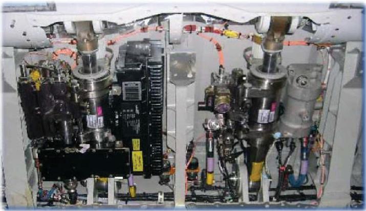
Figure 2 Aileron EHA (left) and conventional hydraulic actuator (right) [7].
2 Operation Condition
To understand the difficult operation conditions and the reasons for wear occurrences, a closer look at the general design of an axial piston pump is beneficial. Figure 3 displays a schematic of an axial piston pump consisting of cylinder block, slipper, piston, swash plate and valve plate. During operation swash plate and the valve plate remain stationary. The pistons are moving linearly within the bores of the rotating cylinder block. The slippers are connected to the piston and are pressed against the swash plate. The slippers allow to increase the load capacity by distributing the load and creating a partial hydrostatic relieve. On top of the pressure forces in the cylinder chambers a spring is installed between the axis and the cylinder block. It ensures a constant pressure between cylinder block and valve plate, thus minimizing internal leakage by ensuring a separation of the suction and high-pressure port.
Like the conventional control system, EHA are responsible for the movement of the primary flight control surfaces. While high pressures and volume flows are needed during start, take-off and turning and have to be available for turbulences, these conditions only make up a small portion of air travel. During quasi-static flight states, the flight control is under load-holding condition with small position changes. Shi et al. [10] placed 71% of all deflection in the range of 2% of the maximum deflection in case of an aileron during cruise state. Further operating cycles are presented in [11].
For an EHA, or an axial piston pump in general, load-holding states are suboptimal, as the rotary speeds are minimal to counter internal leakage while maintaining actuator loads at the same time. This creates high forces on the components while only a small load-bearing film is present, leading to solid friction. Corresponding to small rotary speeds, the fluid flow and thus the EHAs cooling capacity is minimal as well, since the fluid flow transports heat away from its point of origin. In addition, the usage of the pump in bi-directional manner bears the problematic of frequent zero-crossings at which point the relative rotary speed drops to zero. Consequently, the lubrication film between swash plate/slippers and cylinder block/valve plate reduces to the point of contact.

Figure 3 Schematic of an axial piston pump [9].
3 Wear
The operation conditions impact various component surfaces and thus reduce the functionality of the pump. Especially wear is most present in EHA piston pumps, but overheating, oil contamination and cavitation also play a significant role in the deterioration of a pump. A detailed overview over all known influence is given in [9].
3.1 Friction
Generally, all contact pairs are designed to enable a lubrication film to prevent damaging solid contact. In real applications however, force and load spikes increase the probability of mixed and solid friction. While this phenomenon is aimed for in run-ins of axial piston pumps to remove manufacturing deviations, it results in degradation of functional surfaces of contact pairs in normal operation.
Three major friction areas can be identified when looking at Figure 3. Because of the stationary components swash plate and valve plate and the rotary components cylinder block and pistons, a relative rotary movement between valve plate and cylinder block and slipper and swash plate occurs, resulting in wear. Additionally, the pistons move linearly within the cylinder block. Previous investigations at Liebherr Aerospace have shown no significant wear on the later one and the pairing will therefore not be investigated in more detail in the scope of this paper, but can be looked up in [10, 12, 13]. While deterioration on the surfaces between cylinder block and valve plate can be measured, no functionality losses of the EHA can be traced back to this contact pairing. The most common reason for function loss is due to the contact pairing of slippers and swash plate, where solid friction wears down the metallic sealing lands of the slipper (Figure 4).
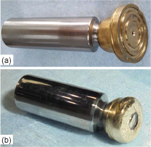
Figure 4 Piston with new (a) and worn down (b) slipper [10, 14].
The sealing lands geometry design is an essential factor for the correct behavior of the pump. Through a bore in the slipper and piston, a small amount of fluid flows to the area between slipper and swash plate, allowing for a pressure build-up, which enables a surface separation. This drastically reduces wear. Outer lands function as control to ensure a homogenous fluid film to all sides and prevent tilting of the slipper. In case of degradation (Figure 4(b)) the lands are worn down. A correct pressure field is no longer possible, resulting in even more wear and inefficiency of the pump.
3.2 Overheating
The capsulated design bears a substantial disadvantage concerning heat dissipation. Conventional hydraulic control systems use the fluid to transport the heat away from the point of origin. In case of an EHA the capsulated architecture combined with the small oil volume narrows the cooling capabilities of the system. Additional cooling surfaces need to be installed to counter the heat development. Increasing temperature results in lower viscosity of the fluid, thus decreasing the load-carrying capacities of the lubrication interfaces and increasing internal leakage and cavitation [15–17]. Rising component temperatures cause thermal deformations, which alter gap heights towards more leakage or friction.
3.3 Oil Contamination
Component wear, unclean installation and maintenance work or unsealed ports can introduce foreign particles in hydraulic circuits. Especially metallic wear particles of different sizes travel through the entire system and cause significant damage. Depending on the particle diameter, filter elements can prevent damages. However, this statement is only correct for particles actually passing the filter. Prior, particles can already lead to severe damages. In general, smaller particles are less harmful than larger ones, which can result in deep scratches in functional surfaces or block pressure relieve bores in pistons and pressure relieve valves.
3.4 Cavitation
Cavitation describes the phenomenon of dynamic formation of gaseous or vaporous cavities in a liquid due to rapid pressure drops [18]. The magnitude of the pressure drop determines the type of cavitation. Below the saturation pressure level of the liquid gaseous cavitation occurs, resulting in the generation of air bubbles. In case of further sudden decrease in pressure, the fluid itself starts to vaporize, creating vapor bubbles. Since the difference between saturation and vaporizing pressure is high, most cavitation appearances are linked to the formation of air bubbles [19]. Damage to components occur when air bubbles travel to areas of high pressure, at which point the air collapses, producing pressure ripples strong enough to create erosion.
When looking at high dynamic axial piston pumps used in EHAs with rotary speeds up to 15,000 rpm and quick acceleration phases, four areas are known to show cavitation. The four areas can be explained in order of appearance during one rotation beginning with the overlay of the piston chamber of a completely retracted piston with the inlet. Here, the remaining oil in the chamber is still at outlet-pressure and thereby higher than inlet-oil. This results in a short backflow to the inlet and thus a significant pressure drop [20]. Afterwards the extracting piston sucks oil into the chamber. Due to the extremely high speeds, high flow speeds are needed to fill the void, again causing a strong pressure drop at the inlet and enabling cavitation [18]. The third area marks the overlay of outlet and piston chamber. At first, the pressure of the outlet is higher than in the piston chamber since the piston has not reached its final retracted position. Hence, oil is flowing from the outlet into the chamber (jet flow), causing a pressure drop at the outer edge of the chamber [9]. Lastly, the high rotary speeds result in strong centrifugal forces within the chambers of the cylinder block, pushing denser fluid to the outside and leaving lighter fluid in the inside, creating a pressure gradient [9]. This phenomenon cannot be neglected in EHAs because of the much higher rotary speeds compared to more common axial piston pumps of mobile or industrial application.
Next to damages mentioned earlier at valve plate, cylinder block and piston, cavitation can have a negative impact on the efficiency of the pump. Especially when rotating at speeds close to maximum, the formation of air bubbles can block the delivery of oil in the chamber and thus not making use of all compression volume and reducing the volumetric efficiency [21]. Additionally, the collapsing bubbles introduce noise and vibration to the system, which subsequently can cause additional damage. To protect against cavitation, EHAs are equipped with preloaded tanks, ensuring a minimal pressure on the inlet side. The pressure drop at the inlet cannot be prevented, but by increasing the initial pressure level the drop does not reach the threshold of gaseous formation.
4 Test Bench and Cycles
To achieve durability requirements for frontline application in modern aviation, the axial piston pump robustness needs to be improved. Liebherr Aerospace developed a test bench to test out different scenarios to identify harmful operation conditions and wear, as well as adjusted pump designs, materials and working fluids. Six of the same test benches were built to run similar test with different fluids, one of which was lend to ifas to conduct separate tests. The test bench will be presented first followed by test cycles developed at ifas.
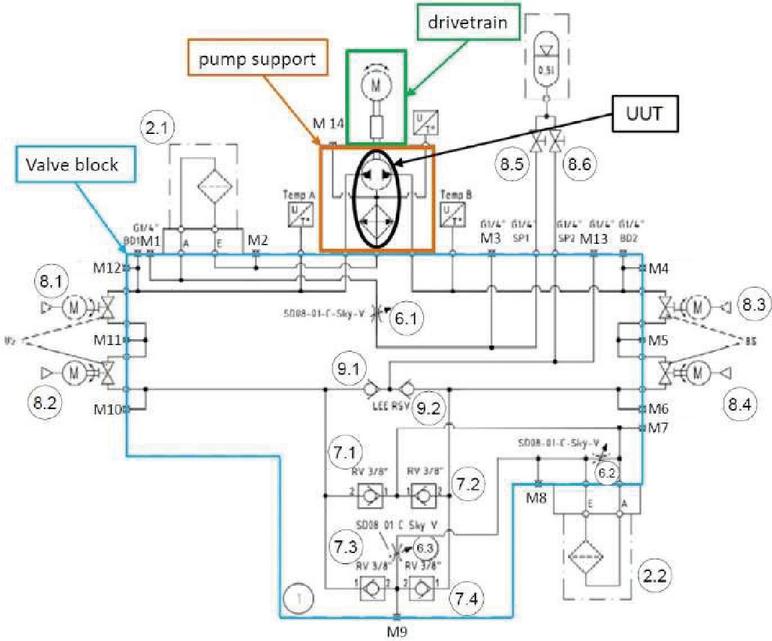
Figure 5 Test bench layout.
4.1 Test Bench
Figure 5 displays the test bench. The bi-directional piston pump is label as UUT (unit under testing) and is connected to a high dynamic piston pump via a magnetic clutch and shaft to best represent the geometry of the EHA. A proportional pressure control valve is used to simulate the applied load. The pressurized oil can flow in either direction through mirrored pneumatic actuated ball valves and check valves to the control valve. Afterwards, the oil flow passes a 5 m filter before continuing to the current low-pressure side of the system.
Lastly, Additional components are a second drain filter, a preloaded tank and cooling channels. An external control unit controls the electric motor. Multiple pressure, temperature and volume flow sensors are installed to monitor every test run.
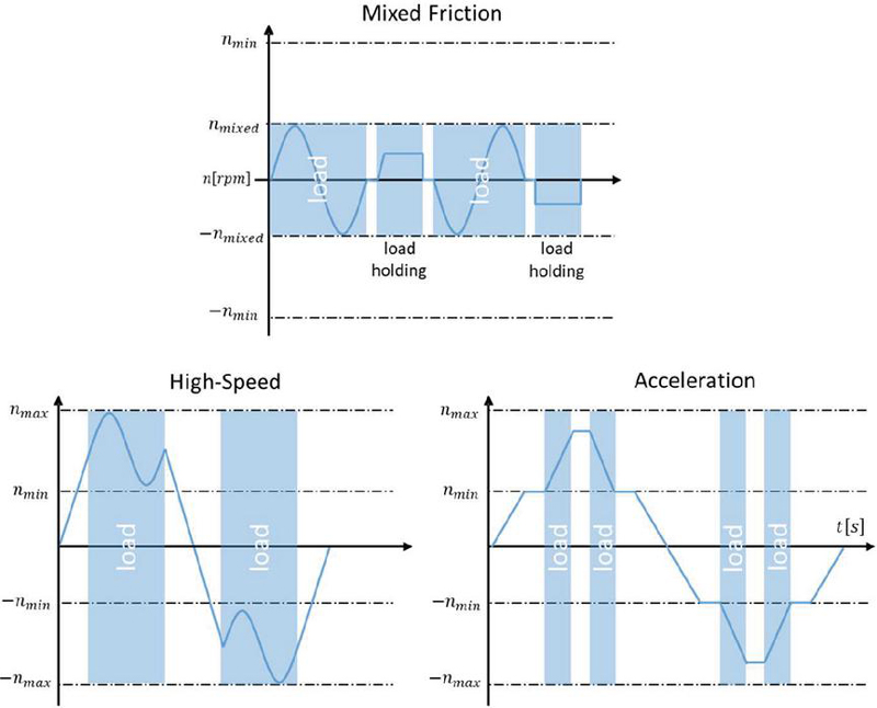
Figure 6 Test profiles.
4.2 Test Cycles
Based on the experience of a LLI test [14], three test cycles (Figure 6) were defined at ifas that best represent real world application to conduct information about the pumps robustness (mixed friction, high speed and acceleration). All test cycles are run sequentially with predefined runtimes according to occurrence frequency in real world application. The cycles consist of three speed profiles and three pressure stages. After each test cycle, the test bench is disassembled and the parts are examined using 3D laser profilometry [22].
As mentioned before, during the most frequent operation the actuator barely moves and only corrects small displacements in both positive and negative direction. The mixed-friction profile represents this behavior by a sine course around zero with low rotary speeds and load-holding states. For both sine and load-holding the same effect of an undeveloped hydro-dynamic relief and thus solid contact is existent.
The high speed profile portrays critical rotary speeds, resulting in wear due to unstable movement like tipping of cylinder block and slippers. The effect is attributed to centrifugal forces and can create larger gaps between contact parings on one side and more solid contact on the opposite side [23]. Additionally, higher speeds result in higher cavitation probability. Similar to the mixed friction profile, a sine course in high positive and negative rotary speeds above a minimal threshold is used. To ensure no other factor play any impact the load during direction changes is lowered to a minimum.
Lastly, the acceleration profile presents all sudden control changes, which can occur during turbulences. Therefore, the profile consists of short accelerations from above mixed friction to high speeds. The load during direction changes is kept to a minimum again.
5 Measurements and Results
The focus of this paper lays in the identification of wear progression by analyzing the load-holding states. Here, the pump comes to a complete halt and, depending on the rotary direction, the first pneumatic piston valve is closed. The speed of the pump is then increased linearly until the pressure reaches a predefined level of 200 bar at which point the second pneumatic ball valve closes to determine the leakage of the first valve.
Figure 7 show the process for six measurements. In the top graph the slow increase in rotary speed from zero is displayed. The bottom graph depicts the simultaneous pressure build-up between pump and pneumatic actuated ball valve 8.1 or 8.2 depending on the rotary direction. Both figures show three measurements of two distant operation times of the test bench, which will be elaborated in more detail later this chapter.
The load-holding procedure is run subsequent to around 270 sine cycles. In total more than 2,700 load-holding measurements were recorded. Four measurement sections are selected to present the findings. Each section consists of 60 load-holding recordings to ensure consistency (Figure 8(a)–8(d)).
In Section 1 the pump is factory new and only run-ins specified by the manufacturer were conducted. First load-holding measurements show an incline to a maximum rotary speed of around 95 rpm (Figure 8(a)). Until the end of the first section, the maximum rotary speed continuously declines to a value of around 85 rpm. Around this level, the rotary speed stagnated (Figure 8(b)). The fluid temperature was consistent at 48C. From the decline in rotary speed first insights can be drawn. Seeing that the oil temperature stayed constant and the leakage over the ball valve remained zero for all measurements the viscosity can be assumed constant as well. Hence, the differences can be traced back to material changes of the pump components. Lower rotary speeds to achieve the same pressure build-up signal a decline in internal and external leakage and thus an improvement in the volumetric efficiency, since the volume between pump and ball valve remains the same. This implies a still ongoing improvement of the functional interfaces due to the reduction of manufacturing deviations.
Section 3 was selected to show the impact of temperature changes on the maximal rotary speeds necessary to reach the defined pressure level. Figure 8(b) presents speeds of around 82 rpm by fluid temperatures of just below 48C, while the measurements of Figure 8(c) were recorded by a temperature of 33C. A comparison of the wear levels of the pumps components prior to both section via 3D profilometry showed negligible differences, allowing to rule out any impact on the pressure build-up due to interface changes. Hence, the differences in maximal rotational speeds are exclusively related to viscosity changes of the fluid because of temperature differences.
Section 4 (Figure 8(d)) presents additional load-holding measurements, recorded after high speed and acceleration test runs, which represent 30% of all expected high speed and acceleration instances of a lifespan. The mean temperature of the measurements is similar to those of section 3 with 31C vs. 33C.
Figure 7 assists to demonstrate the differences of section 3 and 4. Both figures present three courses of the rotational speed ramp and the simultaneous pressure build-up for Sections 3 and 4. The pressure build-up for section 3 is significantly faster, leading to a shorter speed ramp required to achieve the desired pressure limit of 200 bar. In direct comparison, the pressure build up of section 4 is much slower and a higher speed ramp is needed. To exclude other impact factors than wear, viscosity and leakage over the ball valve are investigated. Since the temperature of Sections 3 and 4 are similar, the viscosity can be assumed to be constant. Furthermore, leakage test of the ball valve and inspections of the external oil flow measurements have shown no decisive increases in leakage.

Figure 7 Exemplary rpm ramp (top) and pressure build-up (bottom) of load-holding.
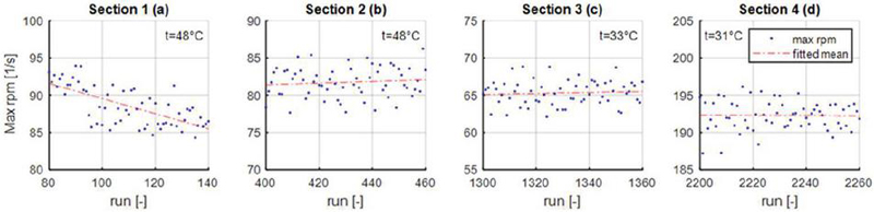
Figure 8 Measurement sections.
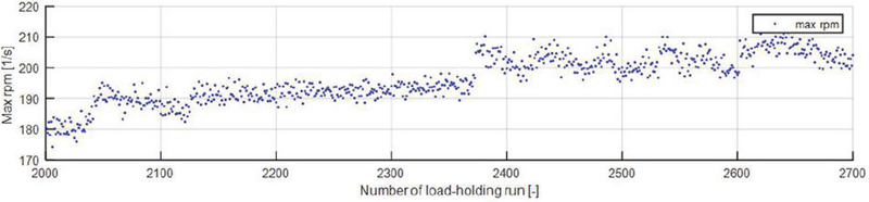
Figure 9 Incline of maximal rpm for load-holding modes.
Hence, the difference in pressure build-up and the required speed ramp are only attributed to internal leakage of the axial piston pump. The additional internal leakage can be traced back to two possible impact factors: an increase in gap height between cylinder block and valve plate and a shift in the changeover point [24]. Increases in gap heights cause a rise in oil flow from outlet to inlet and can be a result of wear between to contact parings. Higher deviations from the mean pressure value imply a shift of the changeover point between cylinder block and valve plate. By shifting the changeover point forwards due to increased gaps in the mounting part of the valve plate, the overlay of chamber and outlet is reached earlier, resulting in higher backflow. Similar, the overlay of chamber and inlet are reached sooner as well, leading to additional backflow towards the low-pressure side. Combined, the maximum potential of the pumps is not utilized since the final extraction point of the piston is reached after piston chamber and outlet disjoin.
The ripples of Figure 7 (2300–2302) represent the short pressure drops in which oil from the outlet side flows back into the piston chamber and the overcompensation afterwards, where the piston completes its movement and the maximal pressure in the chamber is reached. Both impact factors are likely in the test scenario and lower the volumetric efficiency of the pump. They show the significant impact of high-speed and acceleration tests on the pumps wear level.
Finally, by analyzing the last 700 load-holding measurements after the high-speed and acceleration tests a continuous incline in the rotational speed is present (Figure 9). This concludes that the high-speed and acceleration test not only harm the pump interfaces to a certain point of increased internal leakage, but also enabled subsequent wear during mixed-friction operation, further accelerating the deterioration of the pump.
6 Summary and Outlook
Within the scope of this paper, the design and the durability challenges due to demanding operation conditions of electro-hydrostatic actuators in aviation application are presented. A test bench to investigate the main impact factors is shown and test profiles to cover real world conditions explained. By analyzing load-holding states as part of a mixed friction test profile, an insight into run-in processes, temperature dependencies and wear impacts was gained. The analyzed measurements showed further run-in processes after initial predefined run-ins and displayed an increase in internal leakage attributed to a rise in fluid temperature. Finally, a significant increase in internal leakage and thereby decline in efficiency was detected after test runs with high rotational speeds and acceleration states. Load-holding test after the aforementioned test also presented a continuous incline in internal leakage, concluding accelerated wear progression after initial wear occurrences. Since tests are ongoing, future work will continue to investigate the wear progression via analyzing load-holding modes, but also focus on data from 3D profilometry. Lastly, an update to the test bench will allow for temperature, pressure, and vibration measurements of high frequency, which will enable the development of wear detection methods independent from specific test profiles.
Acknowledgment
The content of this paper is created during the project MODULAR, which is funded by the Federal Ministry for Economic Affairs and Climate Actions. Ifas thanks Liebherr-Aerospace Lindenberg GmbH and all project partners who participate in the project.

References
[1] Moir, I.; Seabridge, A.G. Aircraft systems: Mechanical, electrical, and avionics subsystems integration, 3rd ed.; Wiley: Chichester West Sussex England, Hoboken NJ, 2008.
[2] Murrenhoff, H.; Eckstein, L. Fluidtechnik für mobile Anwendungen: Umdruck zur Vorlesung, 5th ed.; Shaker: Aachen, 2011.
[3] Álvarez, M. Sistema Hidraulico: Prezi, ATA 29, 2019.
[4] Habibi, S.; Goldenberg, A. Design of a new high-performance electrohydraulic actuator. IEEE/ASME Trans. Mechatron., 2000, 5, 158–164.
[5] Merkel, A.; Duensing, Y.; Schmitz, K. Electro-hydrostatic Actuators in Primary Flight Control – Lifetime and Reliability: 10th International Conference on Fluid Power Transmission and Control, 2021.
[6] Ivantysyn; Ivantysynova – Hydrostatic Pumps and Motors Prindples, Design, Performance, Modelling, Analysis, Control and Testing - 2001.
[7] Dominique van den Bossche. The A380 flight control electrohydrostatic actuators, achievements and lessons learned.
[8] Roboam, X.; Sareni, B.; Andrade, A. More Electricity in the Air: Toward Optimized Electrical Networks Embedded in More-Electrical Aircraft. EEE Ind. Electron. Mag., 2012, 6, 6–17.
[9] Chao, Q.; Zhang, J.; Xu, B.; Huang, H.; Pan, M. A Review of High-Speed Electro-Hydrostatic Actuator Pumps in Aerospace Applications: Challenges and Solutions. Journal of Mechanical Design, 141, 50801.
[10] Shi, C.; Wang, S.; Wang, X.; Zhang, Y. Variable load failure mechanism for high-speed load sensing electro-hydrostatic actuator pump of aircraft. Chinese Journal of Aeronautics, 2018, 31, 949–964.
[11] Bildstein M. Application of electro-hydrostatic actuators (EHA) for future aircraft primary flight controls. 1. Internationales Fluidtechnisches Kolloquium, Aachen, 1998.
[12] Noah D. Manring, Viral S. Mehta, Bryan E. Nelson, Kevin J. Graf, Jeff L. Kuehn. Scaling the Speed Limitations for Axial-Piston Swash-Plate Type Hydrostatic Machines. Journal of Dynamic Systems, Measurement, and Control, 2014.
[13] Wegner, S.; Gels, S.; Jang, D.S.; Murrenhoff, H. In: ASME/BATH 2015 Symposium on Fluid Power and Motion Control, ASME/BATH 2015 Symposium on Fluid Power and Motion Control, Chicago, Illinois, USA, 12.10.2015 – 14.10.2015; American Society of Mechanical Engineers, 10122015.
[14] Röben, T.; Viennet, E.; Wider, H. Robustness of the Liebherr-Aerospace Technology for Future Flight Control Application. In: 12th IFK, 2020.
[15] L. Shang & M. Ivantysynova. Port and case flow temperature prediction foraxial piston machines. International Journal of Fluid Power, 2015.
[16] Roman Ivantysyn, Prof. Dr. Jürgen Weber. Investigation of the Thermal Behaviour in the Lubricating Gap of an Axial Piston Pump with Respect to Lifetime. In: 11th IFK 2018; pp. 68–83.
[17] Ibuki, T.; Hibi, A., Ichikawa, T.; Yokote, H. Suction Performance of Axial Piston Pump: 2nd Report, Experimental Results. In: JSME; Vol. 20(145); pp. 827–833.
[18] Totten, G.E.; Sun, Y.H.; Bishop, R.J., JR.; Lin, X. Hydraulic System Cavitation: A Review. SAE Transactions, 1998, pp. 368–380.
[19] Schleihs, C.W.; Viennet, E.; Deeken, M.; Ding, H.; Xia, Y.; Lowry, S.; Murrenhoff, H. 3D-CFD simulation of an axial piston displacement unit. In: 9th International Fluid Power Conference (9th IFK) : 24th – 26th March 2014; Vol. 3; pp. 332–343.
[20] Harris, R.M.; Edge, K.A.; Tilley, D.G. The Suction Dynamics of Positive Displacement Axial Piston Pumps. Journal of Dynamic Systems, Measurement, and Control, 1994, 116, 281–287.
[21] Kunkis, M.; Weber, J. In: BATH/ASME 2016 Symposium on Fluid Power and Motion Control, BATH/ASME 2016 Symposium on Fluid Power and Motion Control, Bath, UK, 07.09.2016 – 09.09.2016; American Society of Mechanical Engineers, 09072016.
[22] Merkel, A.; Duensing, Y.; Katharina, S. Identification of wear progression due to variating operation modes of small high dynamic piston pumps used in frontline flight control application. The 13th International Fluid Power Conference, 2022.
[23] Massimo Borghi, Emiliano Specchia, Barbara Zardin; Enzo Corradini. The Critical Speed of Slipper Bearings in Axial Piston Swash Plate Type Pumps and Motors. In: Proceedings of the ASME 2009 Dynamic Systems and Control Conference.
[24] Hong, H.; Zhao, C.; Zhang, B.; Bai, D.; Yang, H. Flow Ripple Reduction of Axial-Piston Pump by Structure Optimizing of Outlet Triangular Damping Groove. Processes, 2020, 8, 1664.
Biographies

Yannick Duensing received a bachelor’s degree in mechanical engineering from RWTH Aachen University in 2016 and a master’s degree in mechanical engineering from RWTH Aachen University in 2019. He is currently working as a Research Associate at the Institute for Fluid Power Drives and Systems at RWTH Aachen University. His research areas include condition monitoring of mobile machinery and axial piston pumps, data analysis, and machine learning.

Amos Merkel received a bachelor’s degree in mechanical engineering from RWTH Aachen University in 2016 and a master’s degree in mechanical engineering from RWTH Aachen University in 2018. He is currently working as a Research Associate and deputy chief engineer at the Institute for Fluid Power Drives and Systems at RWTH Aachen University. His research areas include hydro-mechanical control design, pump robustness and electro-hydrostatic actuators.

Katharina Schmitz received a graduate’s degree in mechanical engineering from RWTH Aachen University in 2010 and an engineering doctorate from RWTH Aachen University in 2015. She is currently the director of the Institute for Fluid Power Drives and Systems, RWTH Aachen University.
International Journal of Fluid Power, Vol. 25_2, 273–290.
doi: 10.13052/ijfp1439-9776.2528
© 2024 River Publishers