Energy-Efficiency Comparison of Different Implement Powertrain Concepts to Each Other and Between Different Heavy-Duty Mobile Machines
David Fassbender1,*, Christine Brach1 and Tatiana Minav2
1Engineering Software and Systems at Bosch Rexroth AG, Elchingen, Germany
2Tampere University, Tampere Finland
E-mail: david.fassbender@boschrexroth.de
*Corresponding Author
This is a conference paper that was presented at the 2022 Global Fluid Power Society PhD Symposium in Naples, Italy.
Received 03 May 2024; Accepted 16 May 2024
Abstract
For the electrification of heavy-duty mobile machine, alternative power-train concepts that are more efficient than conventional valve-controlled systems can be an important key that extends the operation time by making better use of the limited amount of available battery energy. Since power-train concepts are universal and can be applied to various types of heavy-duty mobile machine with different application conditions, it is advisable to assess and compare concepts on multiple of those machines and on the basis of a standardized investigation method. For this purpose, simulations of a telehandler, a wheel loader, and an excavator are done in this study. Each hdmm type is simulated with different setups that each apply one of three concepts: pure conventional valve-control in a ls system, as the benchmark, or one of two alternative concepts that were previously presented by the authors. The two alternative concepts are namely an LS system with the option to replace the metering valves of single actuators with a hydraulic motor connected to an electric generator and secondly a system with an electric machine that drives an ls pump as well as displacement-controlled actuators. The simulations show that both alternative concepts perform equally well on the reference telehandler and the wheel loader with maximum primary energy savings in a work cycle mix of around 37% on both machines compared to the reference setups. For the excavator, on the other hand, the displacement-controlled concept performed even better and reached savings of up to 48%.
Keywords: Heavy-duty mobile machines, implements, energy efficiency, concept assessment.
1 Introduction
Electrification of heavy-duty mobile machine represents an essential measure in fighting global warming. Compared to conventional, diesel-powered heavy-duty mobile machine, electrified machines can avoid local emissions entirely, and over-all emissions can be reduced by utilizing electric energy from renewable sources.
An important aspect with respect to electrification is the energy efficiency of the power trains that transform the electric energy into mechanical energy which is required to fulfill the work task. The more efficient an hdmm is working, the longer it can operate with the limited amount of energy that is provided by its electric battery. Modern batteries still show high specific costs and low energy densities compared to diesel-powered solutions [1], and charging takes much longer than refilling a fuel tank.
While conventional power trains for driving already show high energy efficiencies, the hydraulic valve-controlled systems that are commonly used to realize linear movements of the implements tend to operate very inefficiently – in [5], 21% is mentioned as the average energy efficiency of mobile hydraulic systems. Accordingly, novel, more efficient concepts are required. Many of those were proposed, mainly by academia, over the last decades and gain more attention recently due to the electrification trend. However, it is necessary to evaluate the potential for energy savings of each concept on a common, standardized basis in order to point out solutions that industry should adopt. In most publications, novel concepts are proposed and evaluated for one specific application only. The presented results on efficiency improvement are, therefore, only certainly valid for this specific application and can hardly be transferred to different applications of interest. Furthermore, two concepts that were each evaluated for a different application – with different assumptions and different circumstances – cannot be directly compared to each other.
In [3], the authors already addressed this issue by proposing an evaluation algorithm for matches between power-train concepts and hdmm applications that is based on a number of aspects that can be applied to every potential match of concept and application equally. However, the algorithm is based on assumptions and not on hard facts such as simulation results or measurements. In contrast, the study presented in this paper seeks to provide more reliable evaluations through simulations that are based on measured reference work cycles. Three concepts – pure valve-control in a ls system as the benchmark, and the two alternative concepts [4] and [2] that were previously proposed by the authors – are considered for three different applications of interest – a telehandler, a wheel loader, and a wheeled excavator.
In the next section, the evaluation method is described in more detail, followed by a short description of the three power-train concepts as well as the three hdmm applications. Afterwards, the simulation results are presented and discussed before the paper is concluded.
2 Comparison Method
For the purpose of comparing different concepts to each other and for different applications, a number of different setups that differ in the utilized power-train concept is defined for each of the three heavy-duty mobile machine. The setup definitions can be found in Table 1. More than one setup per concept is defined for the alternative concepts, which are called Concept A and Concept B from now on, since they are modular and can be applied to varying extends. For each setup that belongs to the same type of hdmm, the same work cycle(s) are simulated with the same dynamics. To allow concept comparisons across different hdmm applications, the results are shown as the amounts of primary electric energy that is saved relative to the energy required by the benchmark (Setup 0) – a purely valve-controlled machine – for the same cycle or cycle mix.
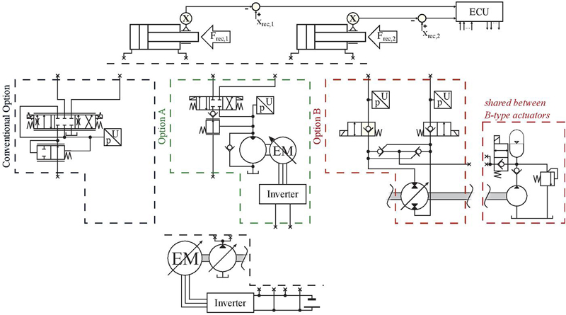
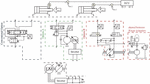
Figure 1 Simplified simulation model of an exemplary setup with two actuators, which can each be connected to the common supply by one of three circuit options.
Table 1 Definition of the actuator options that are used for each setup referring to Figure 2 (not every setup is modelled for each hdmm)
| Actuator functions | |||
| Tilt (Telehandler | Telescope (Telehandler) | ||
| and Wheel Loader) | or Stick (Excavator) | ||
| Setup | Boom | or Bucket (Excavator) | or None (Wheel Loader) |
| 0 | conv. | conv. | conv. |
| A1 | A | A | A |
| A2 | A | conv. | conv. |
| A3 | A | A | conv. |
| A4 | A | conv. | A |
| B1 | B | B | B |
| B2 | B | conv. | conv. |
| B3 | B | B | conv. |
| B4 | B | conv. | B |
Figure 2 shows exemplarily how the simulation model for a setup with two actuators can be modelled. The electro-hydraulic systems are unique for each setup since they utilize different combinations of the three circuit options for each actuator. Moreover, the sizing of the components varies depending on the speed and pressure requirements which differ between the three heavy-duty mobile machine and each of their functions. These electro-hydraulic systems are simulated in Simcenter Amesim and Matlab Simulink in the same way as it was done and described in [4] or [2]. The mechanical load on the hydraulic cylinders and the control inputs, on the other hand, are, for this study, derived from real measurements of representative work cycles. The recorded load force of each differential cylinder is
| (1) |
where is the pressure acting on the piston-side area of that cylinder and the pressure acting on the rod-side area . Even friction effects are included in this force, which simplifies the simulation model of the hydraulic cylinders.
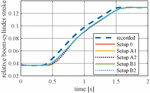
Next to moving under the same load forces, the cylinders in each setup are supposed to follow the exact same load trajectory over time as the machine in the recorded measurements did. Therefore, as shown in Figure 2, the simulated cylinder positions are used to calculate the error compared to the recorded positions, which is then used in the ecu by PI-controllers to actuate the cylinders (the controllers are deactivated as soon as the corresponding joystick signals in the recorded measurements are below a certain threshold). Figure 1 exemplarily shows the trajectory-tracking performance for the boom cylinders of the five wheel-loader setups while they perform the same cycle.
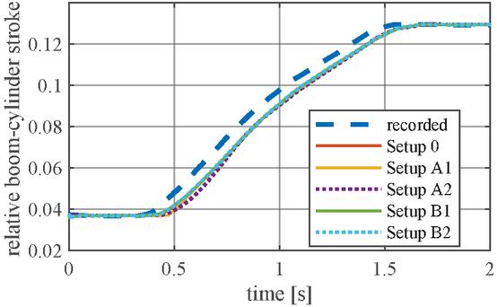
Figure 2 Recorded reference next to simulated wheel-loader boom-cylinder strokes for the first two seconds in Cycle II.
To further assure that all setups are evaluated on the basis of the same work performed by the cylinders in a cycle, in the post-processing, the sum of all mechanical work delivered by all cylinders is obtained from the simulation model. For all setups and simulation runs, the average difference of this energy compared to the energy spend by the reference (Setup 0) in the same cycle is only 0.9%. The differences are caused by the different dynamics of each setup in combination with the PI controllers and by small mass and friction terms that are added to each cylinder in the model for stability reasons. To compensate that minor error, the simulated primary energy consumption is corrected for each run according to
| (2) |
where is the mechanical cylinder energy delivered in Setup 0 for the same cycle. Afterwards, the saved energy relative to the energy spend by Setup 0, , is calculated as
| (3) |
For the heavy-duty mobile machine with more than one simulated cycle, the savings for a representative mix of those cycles, , is calculated as well:
| (4) |
In this equation, is the index for the cycle number; is the total number of cycles in the mix; and is the time share of cycle in the whole mix.
3 Investigated Power-Train Concepts
This section provides more details and references for the conventional benchmark concept as well as for the two alternative concepts, A and B, which aim at improving the energy efficiency.
3.1 Conventional Benchmark Concept
As the benchmark, an electrified valve-controlled ls system is chosen since valve control represents the state-of-the-art technology for powering implements on heavy-duty mobile machine and ls systems are more efficient and thus suitable for electrification than open-center systems, for example.
For the simulations of each of the three heavy-duty mobile machine, models of the control valves that can be found on the original heavy-duty mobile machine are used. Only the pressure gauges are changed from post compensation to pre compensation in order to make the valve models compatible with Concept A, which does not work with a constant ls pressure margin.
Furthermore, the control differs from the original machines in the way that , the ls-pump speed or em speed, respectively, is not fluctuating around a constant nominal speed but it is varied according to the following equation:
| (5) |
represents the volume flow that is estimated from the joystick values, considering the valve characteristics; is the maximum pump displacement; the estimated volumetric efficiency; and the desired displacement ratio. For , a value close to 1 should be chosen to let the pump operate at high and thus efficient displacements. However it should remain smaller than 1 to give the pump-pressure controller a buffer for the case that has been under- or overestimated. In this study, a value of 0.8 has been chosen, and the approach proved to reduce the energy consumption about 3–20% in simulations compared to an approach in which the em drives the pump constantly at its nominal speed. The savings are higher for cycles with low energy turnover as well as frequent and long standstill times of the actuators, such as a loading cycles with a significant amount of pure driving. The improved efficiency with this approach compared to a diesel-powered ls-system should be considered when assessing the results in Section 5.
It should be further noted that for all telehandler cylinders and the boom cylinders of the excavator counterbalance valves are present at the cap sides. The telehandler boom cylinders have them on the rod side as well.
3.2 Concept A
Concept A is based on a conventional ls system that still comprises conventional control valves for functions with low energy turnover. On the other hand, functions with more potential for energy savings are supplied by the same ls pump but utilize a combination of hydraulic motor and electric generator to meter the flow, compensate load pressure differences and to brake loads – all by feeding back electric energy to the DC grid as shown in the middle of Figure 2. The matter of choosing between conventional control valves or the motor-generator unit for each function depends on the type of hdmm and the typical work cycles. To further elaborate this, different configurations are investigated in this study (Setup A1, Setup A2,…). For more details of this concept, the authors refer to their previous publication [4]. Compared to the setups in [4], the concept has been improved in terms of sizing. Switching valves with a larger nominal flow are modeled, and for the telehandler, the maximum flow rates have been reduced to the actual maxima that were obtained from measurements of the original machine.
3.3 Concept B
Same as Concept A, Concept B is also based on an em that is driving an ls pump for low-consuming, valve-controlled functions. In contrast to Concept A, functions with high energy turnover receive an extra variable-displacement pump attached to the same em, which is controlling the actuators in a closed circuit constellation, as shown on the right side of Figure 2. The displacement-control concept was first proposed by Rahmfeld and Invantysynova [6] with an ice as the prime mover, and several further investigations were conducted by their research group. However, for the specific concept in this study with an em as the prime mover and variable shaft speed, the authors refer to their own previous publication [2] for more details. The only difference in this study, compared to the previous study [2], is a change in the load holding mechanism. The cylinders are now locked by electronically controlled on-off valves on each cylinder side, and the on-off valve next to the accumulator is opened whenever the em is spinning to assure sufficient lubrication of the pumps. Furthermore, the accumulator pressure could be reduced for the telehandler that was already investigated in [2] since the new selected holding valves have lower pressure drops which reduces the risk of cavitation at the cylinder.
4 Investigated Heavy-Duty Mobile Machines and Work Cycles
Three hdmm types are chosen for this study that each represent a significant share of the whole hdmm market. Furthermore, the power levels of those machines are in a range at which electrification with acceptable operation time per battery charge has been challenging so far. For those reasons, the authors see a great interest in investigating these three heavy-duty mobile machine.
4.1 Telehandler
The same 9 t telehandler that was previously used as a reference machine in [4] and [2], is used in this study as well. Its original hydraulic implement system has a maximum pump flow of 150 l/min and a maximum pressure of 270 bar. Telehandlers with such specifications can often be found on construction sites as well as in agricultural environments where they mainly perform loading tasks with forks or a bucket as the attached tool. For this reason, three different cycles were recorded that are supposed to represent the average work mix of a telhandler. In analogy to the related previous studies [4] and [2], Cycle I and Cycle II are performed with forks that lift a load close to the maximum reach height of the telehandler. Due to stability issues, measurements could only be done with a load of 1 t, which could furthermore not be unloaded at the top position since such a high structure was not available. Alternatively, Cycle I simulates a load lifting and empty lowering as well as an empty lifting and full lowering by first lifting and lowering the forks to the top position without load and then with load. In Cycle II, a more intense cycle with load lifting and lowering – no empty phase – is recorded – like it might appear in a warehouse. Cycle III is a Y-cycle in which earth is loaded with a bucket from a pile and unloaded into a truck. The time shares of each cycle in the cycle mix, referring to (4), are , , and .
The three main functions boom lifting, tilting the tool, and using the telescope are considered. Since the previous studies [4] and [2] already showed that it is ineffective to improve the tilt actuator, only the setups 0, A2, A4, B2, and B4, which are defined in Table 1, are modelled.
4.2 Wheel Loader
The investigated wheel loader is a 10 t machine, and its original ls system works with a maximum flow of 190 l/min and a maximum pressure of 250 bar. Typical work environments and tasks are similar to those of the previously described telehandler. Similarly, a loading cycle with forks and a 1 t load – Cycle I – as well as a truck-loading cycle with bucket and earth – Cycle II – were recorded for the study. The ratios for (4) are and . The modeled functions are boom lifting and tilting of the attached tool. To consider all possible combinations, the setups 0, A1, A2, B1, and B4 are modeled according to Table 1.
4.3 Excavator
The excavator is the largest hdmm considered in this study with a weight of 17 t and an original ls system that can supply up to 260 l/min. Its upper pressure limit is 360 bar. Furthermore, the chosen model is a wheeled excavator, which is a type common for construction sides.
Since excavators are extremely versatile, no attempt is made to define a work cycle mix that is supposed to be representative for the majority of all excavators. Instead, the focus is on one exemplary cycle only – a 90 digging cycle – which is very common and similar to many other cycles.
The considered functions in the hydraulic system are boom, stick, and bucket movement. The swing function is not considered since it is already common practice for hybrid excavators to directly electrify it without a hydraulic transmission stage [7]. All setups that are defined in Table 1 are modeled and simulated for the excavator.
5 Simulation Results and Discussion
The results are presented and discussed step-by-step, starting with the telehandler. Afterwards, the results of the other two heavy-duty mobile machine are taken into perspective as well in order to analyze differences.
5.1 Telehandler Results
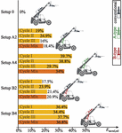
The energy savings of the telehandler setups, compared to the consumption of the benchmark, Setup 0, are presented in Figure 2. Comparing those to the results of the previous studies with the same telehandler can show whether the approach of simulating artificial, generated cycles in those previous studies was legitimate. Study [4] already investigated the A-setups and generally showed similarly high savings. However, the new results in this study – which can be trusted more since they are based on measured work-cycle trajectories and loads – show that Setup A2 performs even better than it seemed in the previous study, which may be caused by a more conservative design of the old, artificial cycles. Study [2], on the other hand, has presented a first study on the B-setups. In this case, the cycle-mix savings of Setup B2 appear to have been overestimated by the previous study, but the results for Setup B4 match surprisingly well between the previous and this study with a difference of less than 1%. All in all, this shows that the approach of conducting simulations with artificial generated cycles in circumstances where no measurements of real cycles are available can be an acceptable tool for obtaining realistic simulation results.

Figure 3 Simulated relative savings of primary electric energy according to (3) and (4) for each telehandler setup.
Moreover, since both concepts, A and B, have now been evaluated under the exact same conditions, they can be directly compared to each other. For the telehandler, both concepts seem to improve the efficiency almost equally well with maximum savings of around 35%. In [2], it was demonstrated that systems with such high efficiencies can be more economic than purely valve-controlled systems, such as Setup 0, due to lower battery and energy costs – even though the costs for the other power-train components, e.g. variable pumps, might rise at the same time. Furthermore, the results show that replacing the conventional control valves of the telescope function with a more efficient option leads to additional saving that are almost as high as for improving the boom actuator – no matter if Concept A or Concept B is used. The only significant performance difference between the concepts seems to be that Concept A is performing better for the fork cycles, I and II, while Concept B shows a stronger performance in Cycle III with a bucket. This can be explained by differences between the cycles in terms of simulations versus serial movements and load differences between the three functions. During simultaneous movements and for high load-pressure differences, more energy needs to be circulated by the actuators in Concept A which is less efficient.
5.2 Wheel-Loader Results
As mentioned before, the wheel-loader cycles are very similar to the telehandler cycles. Thus, it is not surprising that the achievable maximum mix savings as well as the ratios between the different setups that can be seen for the wheel loader in Figure 3 are almost equal to those of the telehandler. Differences are only minor and do not offer more room for further interpretation.

Figure 4 Simulated relative savings of primary electric energy according to (3) and (4) for each wheel-loader setup.
5.3 Excavator Results
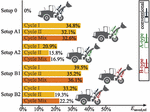
In contrast, the results for the excavator, which are given in Figure 4, show more significant differences to those of the telehandler and wheel loader. An even higher maximum saving of around 48% can be achieved there if all functions utilize option B. Moreover, Concept B appears to be generally more effective for this excavator cycle than Concept A. The reason might be again frequent simultaneous operation of the different functions at significantly different load pressures, which leads to more circulating losses in the systems with A-type actuators. Moreover, the maximum pump pressure limit is higher for the excavator than for the telehandler and wheel loader, which requires the pressure gauges in the A-type actuators to throttle more frequently in order to prevent overpressurization of the hydraulic motors, as it is explained in [4].
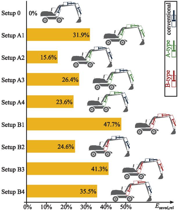
Figure 5 Simulated relative savings of primary electric energy according to (3) for each excavator setup.
Furthermore, it can be seen in the excavator results, that improving the boom function has the highest potential for energy savings, but both other function offer significant potential as well. Looking at this cycle alone, it seems most logical to utilize Concept B rather than Concept A on this excavator and to apply it for the boom and bucket function or even all three functions. However, other typical work cycles should be evaluated as well for a more reliable statement on that.
6 Conclusion and Outlook
In this study, the energy-efficiency performances of a conventional working-hydraulics concept as well as two alternative improved concepts have been evaluated through simulation for three different hdmm applications. The evaluation was conducted on a realistic and common base by modeling the electro-hydraulic systems of the different concepts, sized separately for each application, and using recordings of various representative work cycles to define the loads and trajectories. The obtained results are in line with previous simulation studies of those concepts on a telehandler. Furthermore, the efficiency improvements for common work-cycle mixes were very similar between the telehandler and the wheel loader as well as between the both alternative concepts A and B. Maximum savings of around 37% could be reached for the telehandler and wheel loader. For the excavator and the specific digging cycle, even saving of 48% are reached, and Concept B proved more effective than Concept A.
However, this study was solely focused on energy efficiency. For an over-all assessment of the concepts, aspects such as total costs of ownership, safety, or space and mass limitations must be considered for the different concepts and their setups as well.
The authors prioritize Concept B for future studies on those aspects – especially since the study in [4] has identified pressure amplification as an issue that makes Concept A generally problematic, and study [2] already concluded that Concept B can lead to economic solutions that promise to be competitive on the market.
Acknowledgment
This project received funding from the European Union’s Horizon 2020 research and innovation programme under the Marie Skłodowska-Curie grant agreement No. 858101. 
References
[1] Air Resources Board. Advanced clean transit battery cost for heavy-duty electric vehicles (discussion draft). Technical report, California Environmental Protection Agency, August 2016. URL: https:/www.arb.ca.gov/msprog/bus/battery_cost.pdf.
[2] David Fassbender, Christine Brach, and Tatiana Minav. Using displacement control for single cylinders on an electric mobile machine – improved efficiency versus increased component costs. In 13th International Fluid Power Conference, Aachen, Germany, June 2022. https:/doi.org/10.18154/RWTH-2023-04642doi:10. 18154/RWTH-2023-04642.
[3] David Fassbender and Tatiana Minav. An algorithm for the broad evaluation of potential matches between actuator concepts and heavy-duty mobile applications. Actuators, 10(6), 2021. https:/doi.org/10.3390/act10060111 doi:10.3390/act10060111.
[4] David Fassbender, Tatiana Minav, Christine Brach, and Kalevi Huhtala. Improving the energy efficiency of single actuators with high energy consumption: an electro-hydraulic extension of conventional multi-actuator load-sensing systems. In The 17th Scandinavian International Conference on Fluid Power, SICFP’21, Online, May 2021. https:/doi.org/10.3384/ecp182p74 doi:10.3384/ecp182p74.
[5] Lonnie J Love. Estimating the impact (energy, emissions and economics) of the US fluid power industry. Technical Report ORNL/TM-2011/14, 1061537, Oak Ridge National Lab., Oak Ridge, TN (United States), December 2012. https:/doi.org/10.2172/1061537 doi:10.2172/1061537.
[6] Robert Rahmfeld and Monika Ivantysynova. Energy saving hydraulic actuators for mobile machines. In 1st Bratislavian Fluid Power Symposium, pages 47–57, Bratislava, Slovakia, 1998.
[7] Jixin Wang, Zhiyu Yang, Shaokang Liu, Qingyang Zhang, and Yunwu Han. A comprehensive overview of hybrid construction machinery. Advances in Mechanical Engineering, 8(3), 2016. https:/doi.org/10.1177/1687814016636809 doi:10.1177/1687814 016636809.
Biographies

David Fassbender received a D.Sc.Tech. degree from Tampere University in 2023. Since 2020 he is affiliated with Bosch Rexroth AG where he is working as a systems engineer, developing solutions for heavy-duty mobile machinery.

Christine Brach received a PhD degree in Physics from Ulm University, Germany, in 2003. 23 years ago, she started working at Bosch Rexroth AG and currently holds the position of Vice President Development Software and Systems.

Tatiana Minav received a D.Sc. degree from Lappeenranta University of Technology, Finland, in 2011. She has more than 15 years of experience working on improving the efficiency of heavy-duty mobile machines and works as an associate professor at Tampere University, Finland. Her current research interests include zonal hydraulics, failure detection and monitoring systems based on AI, and energy recovery systems for heavy-duty mobile machines.
International Journal of Fluid Power, Vol. 25_2, 127–144.
doi: 10.13052/ijfp1439-9776.2521
© 2024 River Publishers