Experimental Investigation of the Suction Capabilities of an Innovative High Speed External Gear Pump for Electro-Hydraulic Actuated Automotive Transmissions
Massimo Milani, Luca Montorsi and Fabrizio Paltrinieri*
University of Modena and Reggio Emilia, Department of Sciences and Methods for Engineering, 2 Amendola Street, Reggio Emilia RE 42122, Italy
E-mail: massimo.milani@unimore.it; luca.montorsi@unimore.it; fabrizio.paltrinieri@unimore.it
*Corresponding Author
Received 15 May 2024; Accepted 03 June 2024
Abstract
In this paper, the suction capabilities of an innovative high speed external gear pump have been measured and analysed for verifying its potential use as a reliable and efficient power unit for electro-hydraulic actuated automotive transmissions. In particular, with the aim to face extremely challenging operating conditions, mainly in terms of rotational speed, this specific type of volumetric machine is designed with both two suction and delivery ports. All the experimental measurements have been performed by using a specifically tailored test bench, equipped with a double Cardan joint and an overdrive, designed for running the pump over a wide range of rotational speeds, spanning between 400 and 7000 rpm, and applying a delivery pressure of about 45 bar, very close to a typical actuation value of a high-performance automotive hydraulic transmission. Furthermore, with the aim to confirm the consistency of the experimental measurements, two identical prototypes of the high speed external gear pump have been tested and compared for two different values of the operating temperature, respectively equal to 40 and 60C. First of all, the higher efficiency of the pump primary suction port has been clearly highlighted and evaluated. Moreover, for rotational speed values higher than 4000 rpm, a significant increase of the volumetric flow rate delivered by the pump can be achieved using both the suction ports together and, thus, this particular hydraulic configuration can be considered as a very promising design solution for the entire actuation system.
Keywords: Automotive transmissions, high speed external, gear pump, electro-hydraulic, experimental testing.
1 Introduction
In the last thirty years, a continuous rise of the design requirements of the electro-hydraulic actuated automotive transmissions has been registered, with particular reference to the reduction of the components weights and volumes and of the whole system actuation times and power losses. Furthermore, a considerable growth of the pump delivery pressure targets and of the maximum volumetric flow rate delivered to the hydraulic actuation system has been constantly observed. Following this trend, in order to comply with the progressively more stringent safety regulations and increasing requirements in terms of power density, innovative, miniaturized and more efficient components and subsystems, with advanced features, further functions and evolved control strategies, have been developed, tested and applied. Besides, the contemporary design engineers of electro-hydraulic actuated automotive transmissions have to focus on the achievement of a combined reduction of the components vibrations and emitted noise.
Of course, the optimization of the volumetric pump, usually adopted as the main hydraulic power generation unit of the actuation system, is another central topic in this field. Therefore, being compactness and energy consumption key factors for the development of innovative solutions, the most important efforts are addressed to maximize both the pump specific displacement and its overall efficiency. In order to achieve these objectives, even if a final experimental verification is often required and decisive, lumped and distributed numerical modelling and computational fluid dynamics frequently play a fundamental role.
In recent times, many research papers available in literature, like for instance [1], [2] and [3], have been dedicated to the description of numerical models developed for simulating the real operation of external spur gear machines for fluid power applications and validated by means of a detailed comparison with experimental measurements of the main operating and performance parameters. One of the key factors for all these models is the accurate estimation of the elasto-hydrodynamic behaviour of the clearances existing between the internal components and of the consequent internal leakages. Some further significant contributions are proposed in [4–6] and [7], where this combined numerical and experimental methodology has been employed, respectively, for investigating the operation of external gear units working with non-Newtonian fluids, the wear process due to fluid contamination, the lubricating performance of external gear pumps for aerospace fuel delivery, and the effects of mixed lubrication and cavitation on the dynamic behaviour of the lateral lubricating interfaces.
In the recent past, the flow processes characterizing the gear machines internal clearances and the occurrence of cavitation within the internal chambers have been successfully studied through the application of two innovative testing techniques: flow visualization research method with high speed cameras, as shown in [8] and [9], and particle image velocimetry, as can be seen in [10] and [11]. In all these cases, original and high-performance design solutions have been obtained only with the help of these specific ways of analysis. Frequently, very promising results can be reached by manufacturing properly designed prototypes. An example is presented in [12], where this particular approach has been applied for both increasing the displacement and reducing the flow pulsation of an high-performance elliptical gear pump.
In some cases, the adoption of specifically built up experimental setups can be very useful for diagnostic and detection purposes: in [13], vibration-based techniques are involved to detect, monitor and prevent cavitation in a gear pump used for the lubrication of internal combustion engines, while the capabilities of vibro-acoustic measurements, performed with an hydrophone and an high frequency accelerometer, for detecting external gear pumps incipient cavitation are analysed in [14]. Always in this field, other interesting contributions are devoted to the optimization of the vibro-acoustic performance of a micro-pump, equipped with gears made of different polymer composite materials, in terms of both noise reduction and relatively low vibration level [15], and the development of a custom-made, high-pressure, miniature hydraulic gear pump for bio-medical applications [16].
Some further relevant research activities concerning numerical modelling and experimental testing of other kinds of volumetric pumps are described in papers from [17] to [25]. More in detail, papers [17–21] are devoted to the study of axial piston pumps: in [17], an experimental methodology, based on the observations of the pump vibro-acoustic characteristics, is proposed and successfully applied in order to identify and extract the most relevant noise components during the speed run-up and under steady-state operating conditions; an extremely effective noise reduction technique, based on the suppression of the most dominant discrete-frequency tone by means of a free-layer visco-elastic damping material treatment, is presented in [18]; in [19], specific experimental investigations have been performed with the aim to demonstrate the feasibility and effectiveness of a method using deep belief networks (DBNs) in order to detect multiple faults during axial piston pumps common operation. In [20], a simplified, analytical calculation model has been applied for analysing the material stress of a cylinder block, and its applicability as a valid alternative to more advanced FE-models has been evaluated, verified and clearly demonstrated; the importance of monitoring the operation conditions of axial piston pumps mounted on mini excavators is studied in [21], where the authors outlined that, for mobile machines, accelerometers are not necessary for valve plate fault detection and it’s unrealistic to design a condition monitoring system that can successfully detect incremental faults for every conceivable operating condition.
As clearly established in [22], the development of a positive displacement ORC pump, based on the sliding vane rotary technology, has been achieved through the combined use of a comprehensive one-dimensional numerical model and a wide testing campaign. The great importance of reliable experimental measurements is also evident in [23], where a fast and efficient methodology for pre-screening and ranking of hydraulic fluids is explained and validated through a detailed comparison with the more expensive Vickers vane pump testing procedure. In [24], an iterative spectral methodology, based on multi-physics coupling between periodic gear mesh excitation and upstream/downstream fluctuating loads, is presented and its efficiency, in terms of fast computation with respect to a classical time integration, is illustrated using a practical application to a roots vacuum pump. Finally, in [25], the negative effects of wear and the consequent increase of the gap between the coupled tooth profiles of gerotor pumps have been investigated by means of a detailed mathematical model based on indicators, specifically defined for assessing the effects of changes in geometric parameters on the pump overall performance. In particular, the importance of a wear rate proportional factor (WRPF), as a useful parameter for identifying the profile wear sensitivity, has been highlighted and analysed.
In this paper, the main performance parameters and suction capabilities of an innovative, high speed external gear pump prototype have been accurately investigated, through the use of a specifically assembled test bench, with a driving line equipped with an overdrive and a double Cardan joint, expressly designed for reaching rotational speeds spanning in the range between 400 and 7000 rpm. In all cases, with the aim to evaluate the possible employment of the gear pump prototype as the main volumetric unit for electro-hydraulic actuated automotive transmissions, the influence of different suction configurations and of the fluid working temperature have been tested and analysed. First of all, the capabilities of the two single suction ports are compared and the higher efficiency of the primary one is clearly identified and quantified. Then, the potential advantage in terms of the volumetric flow rate delivered by the pump, due to the combined use of both the suction ports, has been verified and confirmed. In the following paragraphs, the main results obtained at the end of these extensive experimental activities will be presented and discussed.
2 The High Speed External Gear Pump Prototype
In this paper, the Marzocchi GHP2, high speed external gear pump prototype, presented in Figure 1, has been selected and tested with the aim to verify its potential employment as the main volumetric unit of the hydraulic actuation circuit for the last generation automotive transmissions. Usually, these gear pumps consist of a gear pair supported by two aluminium bushes, a body, a securing flange and a front cover and are available in single rotation and reversible. They feature versatility, strength, compact dimensions and long useful life, being suitable for the most different application in both industrial and mobile sectors. Their simple construction ensures limited purchase costs and servicing. For our research purposes, two prototypes, with exactly the same design features, have been provided by the pump manufacturer and, thus, involved for the experimental measurements.
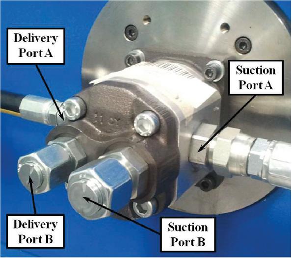
Figure 1 Suction and delivery ports of the innovative Marzocchi GHP2, high speed, external gear pump prototype.
As clearly visible in Figure 1, for this particular pump prototype, two supplementary ports have been added, on the front cover, to the standard ones, usually located on the lateral sides of the pump body. For both suction and delivery ports, the primary is named with letter “A” and the secondary with “B”. With the aim to increase the delivered flow rate when the pump is driven at high rotational speed (3000 rpm), the suction ports are larger than the delivery ones. Moreover, the effective flow area of the primary suction port (port A in Figure 1) is greater than the secondary (port B in Figure 1). The influence exerted by these important design features on the main pump operating and performance parameters will be investigated and discussed in detail in the following paragraphs.
More details concerning the main technical features and performance parameters of the GHP2 external gear pump prototype have been summarized in Table 1. The pump has a light body, made of special hi-resistant aluminium alloy obtained through extrusion process, whereas the securing flange and the front cover are made out of spheroidal cast iron: these design features ensure minimized deformation, even when subjected to high pressure levels. The geared wheels are made of special steel, with twelve teeth, and their manufacturing process includes case-hardening and quench hardening. The gears are ground and fine finished, so to have a high degree of surface finishing. Proper tooth profile design and geometric proportions ensure low pulsation and noise levels during pump operation. Bushings are made of special low-friction and hi-resistant aluminium alloy and manufactured from die-casting. Besides, they are equipped with antifriction DU bearings. On the bushings, specifically dimensioned compensation zones are created and insulated by means of special preformed seals with anti-extrusion rings, in order to guarantee a proper axial and radial balance for a wide range of operating conditions, mainly in terms of rotational speed and delivery pressure.
Table 1 Main technical features and performance parameters of the GHP2 external gear pump prototype
| Feature/Performance Parameter | Value | Unit |
| Displacement | 16 | cm/rev |
| Number of teeth | 12 | – |
| Maximum continuous pressure | 260 | bar |
| Maximum intermittent pressure | 275 | bar |
| Maximum peak pressure | 290 | bar |
| Maximum rotational speed | 4000 | rpm |
The pump displacement is fixed, and its nominal value is equal to 16 cm/rev. It has been designed for a maximum pressure peak of 290 bar while the maximum continuous pressure is limited to 260 bar. Finally, a maximum rotational speed of 4000 rpm is declared by the pump manufacturer. One of the main goals of this research activity was to verify if this limit can be overcome and, in case of positive results, to estimate the correlated volumetric, mechanical and overall efficiencies.
3 Experimental Test Rig
The most important aim of the research activities described in this paper is to verify the possibility of employing the innovative high speed external gear pump as the main volumetric unit of the hydraulic actuation system of a modern robotized transmission for automotive applications. For this purpose, the test bench shown in Figure 2, specifically designed for testing external gear pumps and motors, with a maximum installed electric power of 35 kW and a maximum admitted rotational speed of 3500 rpm, has been involved in order to achieve the experimental measurements.
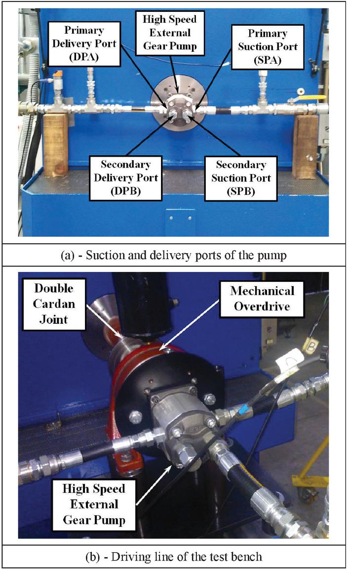
Figure 2 Test rig used for the pump experimental characterization ((a) suction and delivery ports of the pump, (b) driving line of the test bench).
In particular, in the upper frame of Figure 2, the pump and all its suction and delivery ports (both primary and secondary) are highlighted, while the lower frame of Figure 2 shows the driving line of the test bench, where the presence of a Comer PG 101 CP/P overdrive, with a transmission ratio equal to 3.55, and a double Cardan joint can be noticed.
It is important to underline that, with the adoption of these two additional components, the maximum pump rotational speed can be increased to about 9000 rpm, even if, for safety reasons, during the execution of all the experimental tests described in this paper, the pump maximum rotational speed has been limited to 7000 rpm. A tank and an auxiliary cooling system, equipped with a thermostat and an air-cooled heat exchanger (not visible in Figure 2), are located over the main structure of the test bench.
For clarity, in Figure 3, the hydraulic scheme of the experimental test rig is depicted, together with the labels introduced for identifying the main components and sensors. During the testing procedure, an electric motor is driving the volumetric pump and a variable orifice is used for regulating the delivery pressure. In this particular configuration, the secondary suction (SPB) and delivery (DPB) ports of the pump are not involved and, thus, are closed. The actual pressure drop applied to the pump is evaluated by means of two pressure sensors, installed in the suction (SPS) and delivery (DPS) lines. The mechanical power that is necessary to run the pump can be estimated by the combined presence of a torque (TORS) and a rotational speed (RSS) sensor, mounted between the pump and the electric motor. The monitoring system of the pump working conditions is completed with the help of a temperature (DTS) and a flow rate (FRS) sensor, respectively placed before and after the pump delivery pressure regulator. More details about the testing setup and the main features and technical data of the sensors involved for the pump experimental characterization are described in [26].
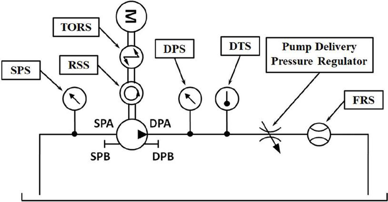
Figure 3 Hydraulic scheme of the test rig implemented for the pump experimental characterization.
Table 2 Main features and physical properties of the Shell Tellus T46 hydraulic fluid
| Feature/Physical Property | Value | Unit |
| Density @ T = 15C | 872 | kg/m |
| Kinematic viscosity @ T = 20C | 2350 | mm/s |
| Kinematic viscosity @ T = 40C | 46 | mm/s |
| Kinematic viscosity @ T = 100C | 7.9 | mm/s |
| Flash Point | 225 | C |
| Pour Point | 39 | C |
Finally, the most important features and physical properties of the hydraulic fluid (Shell Tellus T46) employed for the experimental characterization of the high speed external gear pump prototypes are summarized in Table 2. Analysing the numerical values listed in Table 2, when the operating temperature is increased from 40 to 100C, a significant reduction of the fluid kinematic viscosity can be noted (from 46 to 7.9 mm/s).
4 Analysis of the External Gear Pump Suction Capabilities
Nowadays, the main efficiency parameters and the maximum delivered flow rate for a given displacement are key factors in order to evaluate the potential use of an advanced volumetric pump as a power unit for the hydraulic circuit of the last generation, electro-hydraulic actuated, automotive transmissions. In this sense, the suction and delivery capabilities of the innovative high speed external gear pump have been accurately investigated by comparing the experimental measurements performed using both the available suction ports. More in detail, as previously shown in Figure 1, the pump has two different suction ports: the first one, conventionally named as A (SPA in Figure 3), is the main suction port of the pump; the other one, named as B (SPB in Figure 3), is the secondary suction port and is located on the front cover, in perpendicular direction with respect to the first one and parallel to the axis of the pump mechanical shaft.
First of all, the results achieved for the two suction ports have been directly compared in the next Figures from 4 to 15, testing the first pump prototype (pump nr. 1) and imposing a fixed delivery pressure equal to 45 bar. Two temperature levels, respectively equal to 40 and 60C, have been taken into account. In these figures, the diagrams of the delivery flow rate, suction pressure, torque necessary to run the pump and of the volumetric, mechanical and overall efficiencies, as functions of the pump rotational speed, have been illustrated.
As well known, the pump volumetric efficiency, , is defined as the ratio between the volumetric flow rate really delivered by the pump, Q, and an ideal one, Q, computed as the product between the pump displacement, V, and angular speed, :
| (1) |
Obviously, for our purposes, the pump real flow rate, indicated as Q in Equation (1), has been directly measured with the help of a turbine flow sensor, mounted in the pump delivery line. Thus, as highlighted on the right hand of Equation (1), it can be also designated as Q. It is worth noting that the ideal flow rate is always higher than the real one, being their difference a direct consequence of the pump internal leakages between the delivery and the suction ambient.
At the same time, the pump mechanical efficiency, , is given by the ratio between the ideal, T, and the real, T, torque necessary to run the pump:
| (2) |
In Equation (2), the ideal torque, T, is defined as the product of the pump displacement, V, and the pressure drop, p, measured between the delivery and the suction port, while the real torque, T, has been estimated with the adoption of the test bench torque sensor and, thus, also named as T. In this case, the real torque always exceeds the ideal one and the difference is mainly due to the energy losses associated with mechanical and viscous frictions between pump internal components.
Finally, the pump overall efficiency, , can be computed as the product between the volumetric and the mechanical efficiency:
| (3) |
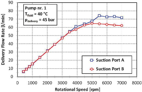
Figure 4 Influence of the suction ports (A and B) on the high speed external gear pump delivery flow rate – Fluid temperature: 40C.
During the execution of the experimental tests, the temperature and pressure targets have been satisfactorily maintained. For this reason, the delivery temperature and pressure are neglected. Very similar results have been obtained for a second pump prototype (pump nr. 2) and, consequently, have been omitted in this paper. Moreover, for this analysis, a blue solid line with squared markers is used for identifying the operating and performance parameters referred to the main suction port (port A), while a red solid line with rounded markers indicates the secondary port (port B).
Two opposite trends can be identified for the experimental measurements of the delivery flow rate (see Figure 4): for the lower rotational speed values (4000 rpm), no difference can be observed; on the other hand, for the higher revving (4000 rpm), the benefit of using the main suction port (port A) becomes gradually evident, being the maximum difference, in terms of delivered flow, of about 9 l/min (74 l/min with respect to 65 l/min).
Obviously, similar considerations can be written also for the volumetric efficiency (see Figure 5). In this case, for the higher speeds values (5500 rpm), the gap is always comprised between 9% and 11%. Otherwise, for the lower speeds, no significant difference can be appreciated.
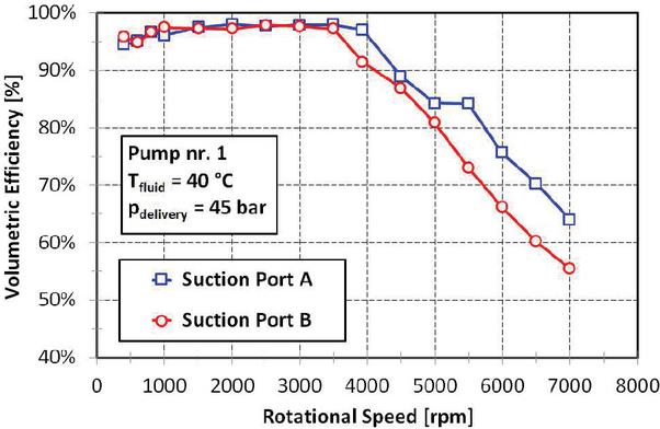
Figure 5 Influence of the suction ports (A and B) on the high speed external gear pump volumetric efficiency – Fluid temperature: 40C.
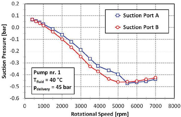
Figure 6 Influence of the suction ports (A and B) on the high speed external gear pump suction pressure – Fluid temperature: 40C.
The different geometric and effective flow area of the two ports affects the suction pressure measurements (Figure 6). Thus, when the pump is operated at low speed (5500 rpm), the greater lumped pressure losses due to the limited effective flow area of the secondary inlet port (port B) with respect to the primary (port A) are the main reason of the lower suction pressures. Then, when the rotational speed is increased over 5500 rpm and the delivered flow rate is above 60 l/min, both the suction ports are saturated and the pressure curves are coincident. For the maximum rotational speed (7000 rpm), the measured suction pressure is equal to 0.45 bar.
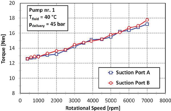
Figure 7 Influence of the suction ports (A and B) on the torque required to run the high speed external gear pump – Fluid temperature: 40C.
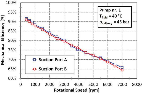
Figure 8 Influence of the suction ports (A and B) on the high speed external gear pump mechanical efficiency – Fluid temperature: 40C.
As expected, no influence of which suction port is used can be observed on the torque required to run the pump (Figure 7) and, consequently, on the pump mechanical efficiency (Figure 8), being these operating and performance parameters only determined by the action of the mechanical and viscous friction losses. Also in this case, the torque is linearly growing from about 12.5 to 17.5 Nm, while the mechanical efficiency is decreasing from 92% to 65%.
Finally, the diagram of the overall efficiency (Figure 9) can be easily understood by considering both its definition, introduced with Equation (3), and the tendencies of the volumetric and mechanical efficiencies.
Obviously, the most conditioning factor is the volumetric efficiency: when the rotational speed is lower than 4000 rpm, the differences are very limited and the values are almost the same; at higher speeds (4000 rpm), a clear advantage of about 6–7%, for the primary suction port, is manifest. For instance, at 7000 rpm, the comparison is between 42% (port A) and 36% (port B).
The same comparison between the performance acquired when the two available suction ports are used for feeding the pump has been also performed for an higher temperature level, equal to 60C.
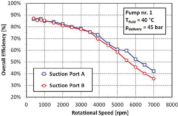
Figure 9 Influence of the suction ports (A and B) on the high speed external gear pump overall efficiency – Fluid temperature: 40C.
The experimental measurements of the most important operating parameters and of the calculated efficiencies are shown in the next Figures from 10 to 15. The main considerations, previously described and discussed for the lower working temperature, can be repeated again and are still applicable, even if some marginal differences can be highlighted.
As already stated, at high temperature, the fluid lower viscosity values lead to enhanced internal leakages and decreased pressure losses in the suction line and viscous frictions between the pump internal components.
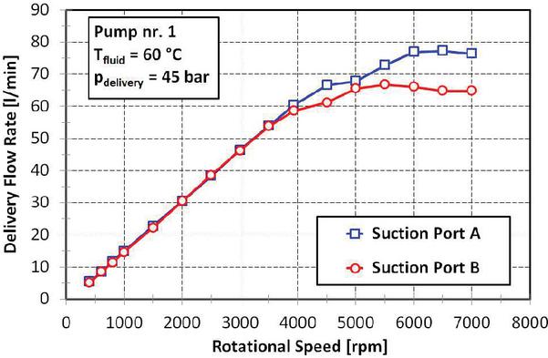
Figure 10 Influence of the suction ports (A and B) on the high speed external gear pump delivery flow rate – Fluid temperature: 60C.
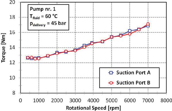
Figure 11 Influence of the suction ports (A and B) on the torque required to run the high speed external gear pump – Fluid temperature: 60C.
Therefore, the following outcomes can be listed:
• the pump delivered flow rate (Figure 10) is always greater, particularly at high rotational speed and for the primary suction port: the maximum delivery flow rate is near to 80 l/min;
• the torque necessary to run the pump is moderately decreasing (Figure 11) and always lower than 17 Nm;
• the reduction of the suction pressure (Figure 12) is limited and, however, always greater than 0.4 bar;
• lower volumetric (Figure 13) and higher mechanical (Figure 14) efficiencies have been computed and the balance between these two contrasting trends determines a negligible effect on the overall efficiency (Figure 15);
• only for very low rotational speeds (1000 rpm), a significant reduction of the overall efficiency is registered, from values greater than 85% to lower than 80%.
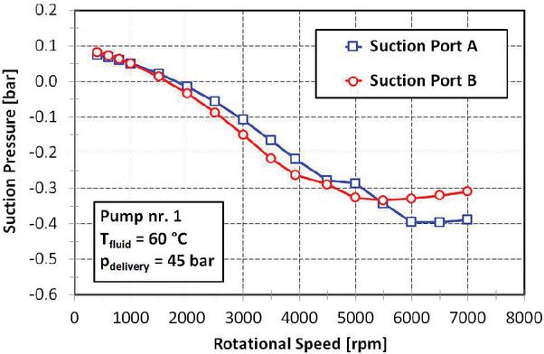
Figure 12 Influence of the suction ports (A and B) on the high speed external gear pump suction pressure – Fluid temperature: 60C.
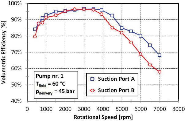
Figure 13 Influence of the suction ports (A and B) on the high speed external gear pump volumetric efficiency – Fluid temperature: 60C.
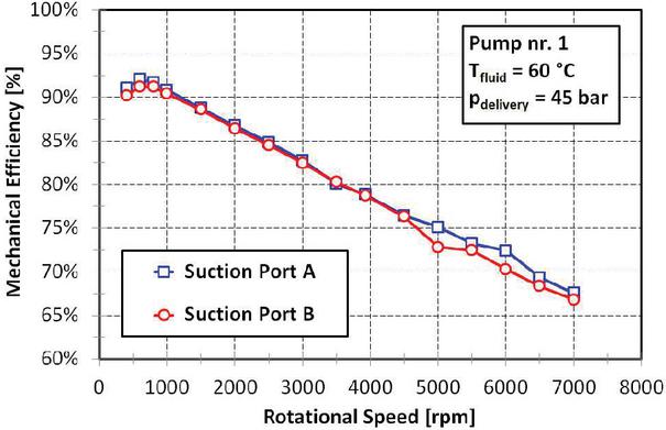
Figure 14 Influence of the suction ports (A and B) on the high speed external gear pump mechanical efficiency – Fluid temperature: 60C.
The maximum suction and, thus, delivery capability of the high speed external gear pump, shown in Figure 1, can be achieved by using together both the accessible suction ports. This particular hydraulic configuration, identified as “Suction Ports A + B”, has been tested and compared with the one using only the primary inlet port (named as “Suction Port A”).
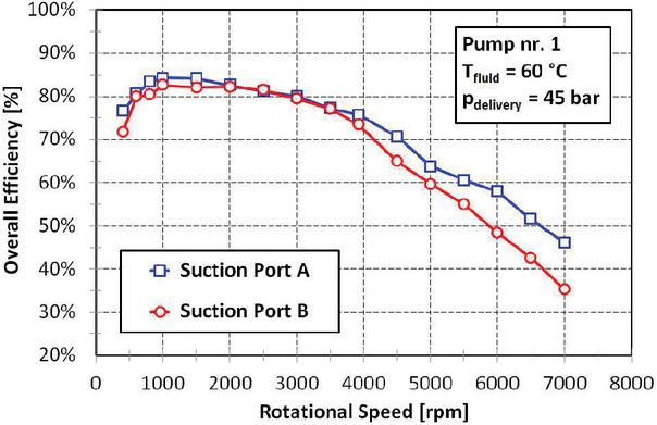
Figure 15 Influence of the suction ports (A and B) on the high speed external gear pump overall efficiency – Fluid temperature: 60C.
As previously explained, the usual delivery pressure (45 bar) and fluid temperatures (40 and 60C) have been considered during the testing procedures and the main results acquired for the first prototype (pump nr. 1) are presented in the following Figures from 16 to 27, in terms of delivery flow rate, torque necessary to run the pump, suction pressure, and of the volumetric, mechanical and overall efficiencies.
For all the diagrams sketched in these figures, the single port hydraulic configuration is represented with a blue solid line with squared markers and the other one with a red solid line with rounded markers. The measurements performed for the second prototype (pump nr. 2) are comparable and, for brevity, have not been included in this paper. More details concerning the comparison between the experimental results obtained for the two tested prototypes can be found in [26].
Firstly, for rotational speeds greater than 4000 rpm, considerably increased performance can be remarked for the configuration using both suction ports, mainly in terms of delivered flow (Figure 16), suction pressure (Figure 17) and volumetric efficiency (Figure 18).
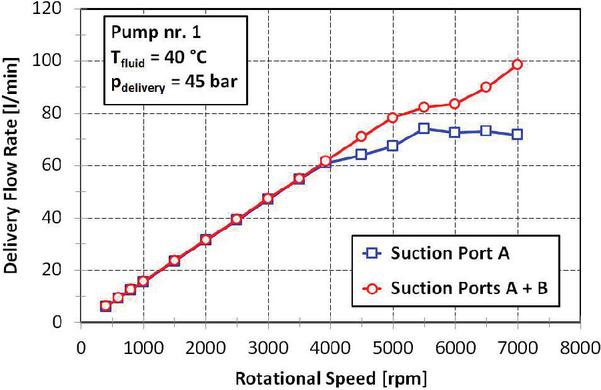
Figure 16 Influence of the suction ports (A and A + B) on the high speed external gear pump delivery flow rate – Fluid temperature: 40C.
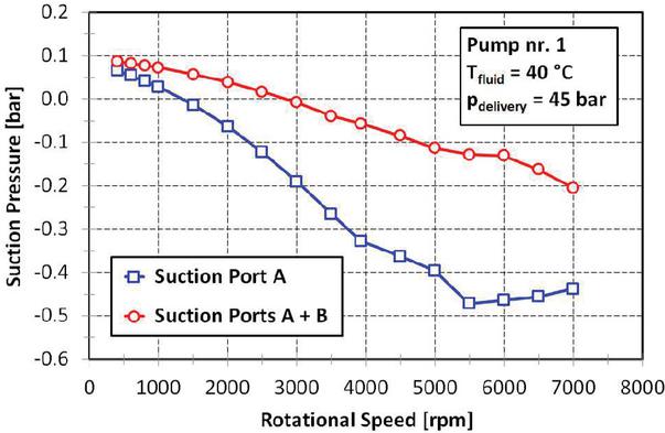
Figure 17 Influence of the suction ports (A and A + B) on the high speed external gear pump suction pressure – Fluid temperature: 40C.
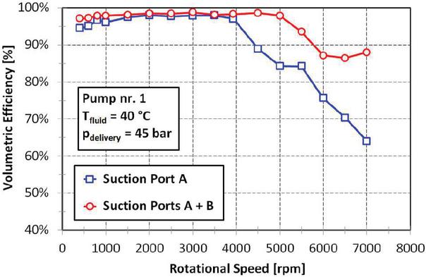
Figure 18 Influence of the suction ports (A and A + B) on the high speed external gear pump volumetric efficiency – Fluid temperature: 40C.
More in detail, at the maximum tested speed (7000 rpm), the delivery flow rate is near to 100 l/min, the suction pressure rises to about 0.2 bar, and a volumetric efficiency of about 88% is reached. Otherwise, for the lower speeds (4000 rpm) and, particularly, for the delivery flow rate and the volumetric efficiency, the differences are extremely limited. Moreover, when the pump is fed using both inlet ports, the reduction of the suction pressure is less appreciable for the whole operating range, because of the increased suction effective flow area and, thus, of the decreased resulting pressure losses.
The curves concerning the torque needed to run the pump (Figure 19) and the mechanical efficiency (Figure 20) are almost coincident, confirming the conclusions already outlined for the comparison between the results measured for the two suction ports used one by one.
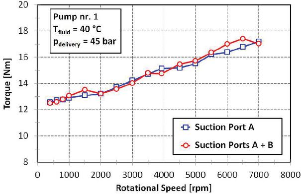
Figure 19 Influence of the suction ports (A and A + B) on the torque required to run the high speed external gear pump – Fluid temperature: 40C.
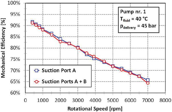
Figure 20 Influence of the suction ports (A and A + B) on the high speed external gear pump mechanical efficiency – Fluid temperature: 40C.
At the end, for the higher rotational speed values (4000 rpm), a noteworthy improvement of the overall efficiency can be observed (Figure 21), being the maximum enhancement near to 15% (from 42% to about 57%). Differently, when the pump speed is lower than 4000 rpm, the overall efficiency is almost unvaried and no influence can be recognized for the suction configuration.
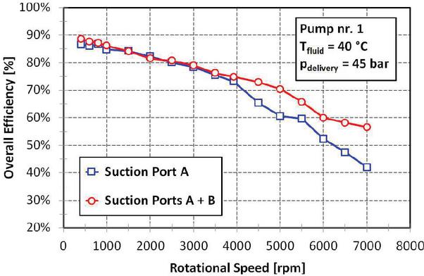
Figure 21 Influence of the suction ports (A and A + B) on the high speed external gear pump overall efficiency – Fluid temperature: 40C.
As depicted in the diagrams shown in the next Figures (from 22 to 27), this comparison between different suction layouts has been also repeated for the higher operating temperature (TC), following the same approach and in terms of the same operating and performance parameters. The performance improvement is mostly confirmed for the whole operating range of the pump. Actually, at higher temperature, the negative effect of the increased internal leakages is balanced by the contemporarily reduction of the lumped and distributed pressure losses in the suction line and of the viscous frictions between the internal components.
In particular, for the maximum rotational speed (7000 rpm), the delivered flow rate is near to 100 l/min (Figure 22); the suction pressure rises to about 0.13 bar (Figure 23); a volumetric efficiency of about 87% (Figure 24) and an overall efficiency near to 60% (Figure 25) are computed.
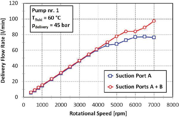
Figure 22 Influence of the suction ports (A and A + B) on the high speed external gear pump delivery flow rate – Fluid temperature: 60C.

Figure 23 Influence of the suction ports (A and A + B) on the high speed external gear pump suction pressure – Fluid temperature: 60C.
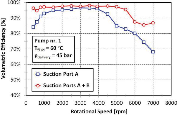
Figure 24 Influence of the suction ports (A and A + B) on the high speed external gear pump volumetric efficiency – Fluid temperature: 60C.
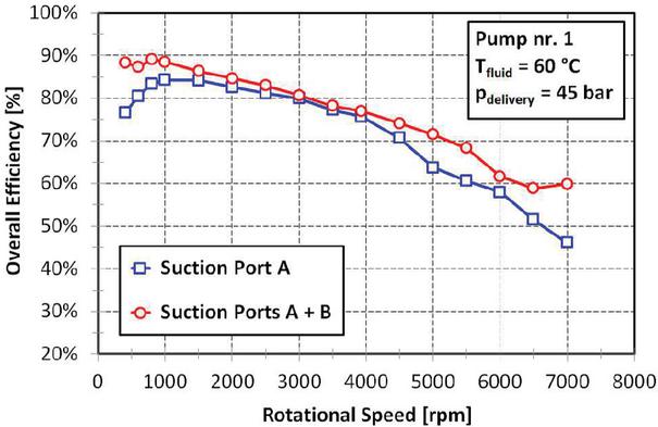
Figure 25 Influence of the suction ports (A and A + B) on the high speed external gear pump overall efficiency – Fluid temperature: 60C.
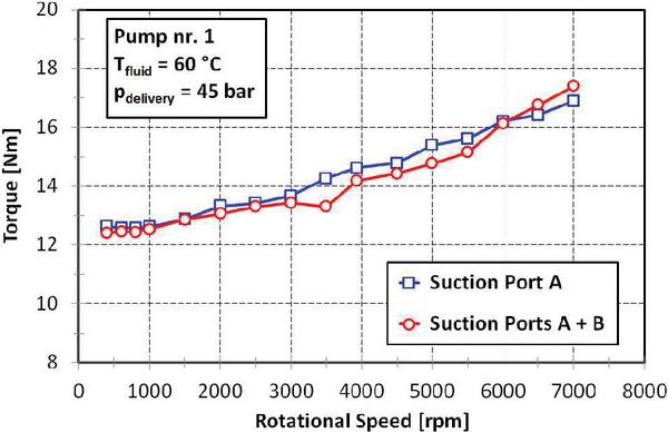
Figure 26 Influence of the suction ports (A and A + B) on the torque required to run the high speed external gear pump – Fluid temperature: 60C.
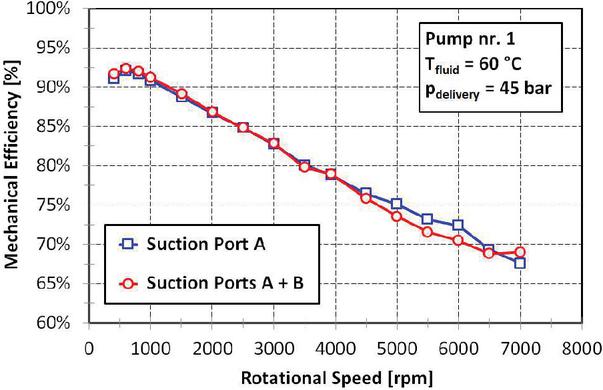
Figure 27 Influence of the suction ports (A and A + B) on the high speed external gear pump mechanical efficiency – Fluid temperature: 60C.
Also for these operating conditions, the differences in terms of torque (Figure 26) and mechanical efficiency (Figure 27) are very limited and have a negligible influence on the calculated values of the pump overall efficiency.
Consequently, the volumetric efficiency is the most conditioning factor for the pump overall efficiency and its higher enhancements are achieved when both the suction ports are used together at very low (1500 rpm) and very high (4500 rpm) rotational speed. For the lower and the higher speeds here tested, the suction configuration with an increased geometric and effective flow area leads to consistent improvements of the overall efficiency, respectively estimated in about 11% (from 77% to 88% at 400 rpm) and 14% (from 46% to 60% at 7000 rpm).
For this last analysis, the following considerations can be summarized:
• no significant influence of the fluid temperature on the pump delivered flow rate is manifest;
• the suction pressure is increasing with the fluid temperature, because of the reduced fluid frictions determined by lower viscosity values;
• at higher temperature, a slight reduction of the torque necessary to run the pump can be noticed, as a consequence of the decreased mechanical and viscous frictions;
• the mechanical efficiency is increasing with temperature, being the maximum difference always limited to 3%.
5 Conclusions
In this paper, the most important results of detailed experimental measurements, aimed at investigating the suction capabilities of an high speed external gear pump prototype, are presented and analysed. In fact, the presence of two additional ports, located on the front cover, is the most interesting design feature of this innovative prototype and could be helpful in order to improve its performance in terms of increased suction pressure and delivered flow rate, particularly at higher rotational speeds.
The main goal of this experimental activity is to evaluate the potential use of this particular type of pump as a reliable and efficient volumetric unit for the hydraulic actuation circuit of the last generation automotive transmissions. Consequently, two pump prototypes, with exactly the same design features, have been subjected to operating conditions that are comparable to those of an actual electro-hydraulic actuated transmission for high-performance automotive vehicles. Through the use of a specifically assembled test bench, with a modified driving line equipped with an overdrive and a double Cardan joint, the pump rotational speed has been varied between 400 and 7000 rpm, while an almost stable delivery pressure of about 45 bar has been applied for two fluid temperatures, respectively equal to 40 and 60C.
Particular care has been devoted to the comparison between the hydraulic performance of different suction configurations. As expected, because of the greater effective flow area, the primary suction port is more efficient than the secondary. For the maximum rotational speed of 7000 rpm, the measured gains in terms of delivered flow rate and volumetric efficiency have been respectively assessed in about 10 l/min and 10%. Moreover, when the pump rotational speed exceeds 4000 rpm, a further improvement can be achieved by using together both the suction ports. For this particular suction layout, the maximum delivered flow rate is near to 100 l/min and the volumetric efficiency is always over 85%.
The influence of the fluid temperature on the main pump operating and performance parameters has been also inspected, by increasing its value from 40 to 60C. In this case, a sort of compensation mechanism between the reduced volumetric efficiency and the increased mechanical efficiency is established and, thus, the resulting overall efficiency remains almost unvaried. For rotational speeds under 1000 rpm, when the fluid temperature is higher, the advantage of the hydraulic configuration using both the suction ports, in terms of the overall efficiency, is clearly evident and can be quantified in about 15% at 400 rpm.
At the end of this wide campaign of experimental measurements, it is possible to conclude that the main performance parameters, and particularly the suction capabilities, of the innovative high speed external gear pump prototype are very encouraging, for the entire scope of testing conditions. Therefore, the hydraulic configuration using both the suction ports can be surely considered as a promising alternative design solution for the volumetric pumps of the modern, electro-hydraulic actuated transmissions for automotive applications.
Acknowledgements
Authors would like to particularly acknowledge Oerlikon Graziano S.p.A. (Rivoli, Turin, Italy) and, in particular, Dr. R. Gay, Dr. A. Noto, Dr. C. Cavallino and Dr. F. Irato for providing both the pump prototypes and for their support at the development of all the experimental activities.
A special thank also goes to Dr. A. Masia for the valuable suggestions proposed during his bachelor degree thesis.
References
[1] A. Vacca and M. Guidetti, “Modelling and experimental validation of external spur gear machines for fluid power applications”, Simulation Modelling Practice and Theory, vol. 19, issue 9, pp. 2007-2031, 2011. DOI: https:/doi.org/10.1016/j.simpat.2011.05.009.
[2] E. Mucchi and G. Dalpiaz, “Elasto-dynamic analysis of a gear pump-Part III: Experimental validation procedure and model extension to helical gears”, Mechanical Systems and Signal Processing, vol. 50–51, pp. 174-192, 2015. DOI: https:/doi.org/10.1016/j.ymssp.2014.05.048.
[3] A.V. Svishchev and I.P. Aistov, “The theoretical and experimental studies comparison of the pressure pulsation in the discharge chamber of the gear pump”, Procedia Engineering, vol. 113, pp. 186–191, 2015. DOI: https:/doi.org/10.1016/j.proeng.2015.07.316.
[4] F. Rituraj and A. Vacca, “External gear pumps operating with non-Newtonian fluids: Modelling and experimental validation”, Mechanical Systems and Signal Processing, vol. 106, pp. 284–302, 2018. DOI: https:/doi.org/10.1016/j.ymssp.2017.12.042.
[5] R.H. Frith and W. Scott, “Comparison of an external gear pump wear model with test data”, Wear, vol. 196, issues 1-2, pp. 64–71, 1996. DOI: https:/doi.org/10.1016/0043-1648(95)06845-7.
[6] D. Thiagarajan, A. Vacca and S. Watkins, “On the lubrication performance of external gear pumps for aerospace fuel delivery applications”, Mechanical Systems and Signal Processing, vol. 129, pp. 659–676, 2019. DOI: https:/doi.org/10.1016/j.ymssp.2019.04.030.
[7] T. Ransegnola and A. Vacca, “Virtual Design and Analysis of the Balancing Element of an External Gear Machine Considering Cavitation and Mixed Lubrication Effects”, International Journal of Fluid Power, vol. 24, iss. 1, pp. 77–98, River Publishers, 2023. DOI: https:/doi.org/10.13052/ijfp1439-9776.2414.
[8] P. Antoniak and J. Stryczek, “Visualization study of the flow processes and phenomena in the external gear pump”, Archives of Civil and Mechanical Engineering, vol. 18, issue 4, pp. 1103–1115, 2018. DOI: https:/doi.org/10.1016/j.acme.2018.03.001.
[9] J. Stryczek, P. Antoniak, O. Jakhno, D. Kostyuk, A. Kryuchkov, G. Belov and L. Rodionov, “Visualisation research of the flow processes in the outlet chamber-outlet bridge-inlet chamber zone of the gear pumps”, Archives of Civil and Mechanical Engineering, vol. 15, issue 1, pp. 95–108, 2015. DOI: https:/doi.org/10.1016/j.acme.2014.02.010.
[10] N. Ertürk, A. Vernet, R. Castilla, P.J. Gamez-Montero and J.A. Ferre, “Experimental analysis of the flow dynamics in the suction chamber of an external gear pump”, International Journal of Mechanical Sciences, vol. 53, issue 2, pp. 135–144, 2011. DOI: https:/doi.org/10.1016/j.ijmecsci.2010.12.003.
[11] N. Ertürk, A. Vernet, J. Pallares, R. Castilla and G. Raush, “Small-scale characteristics and turbulent statistics of the flow in an external gear pump by time-resolved PIV”, Flow Measurement and Instrumentation, vol. 29, pp. 52–60, 2013. DOI: https:/doi.org/10.1016/j.flowmeasinst.2012.09.004.
[12] D. Liu, Y. Ba and T. Ren, “Flow fluctuation abatement of high-order elliptical gear pump by external noncircular gear drive”, Mechanism and Machine Theory, vol. 134, pp. 338–348, 2019. DOI: https:/doi.org/10.1016/j.mechmachtheory.2019.01.011.
[13] D. Siano and M.A. Panza, “Diagnostic method by using vibration analysis for pump fault detection”, Energy Procedia, vol. 148, pp. 10–17, 2018. DOI: https:/doi.org/10.1016/j.egypro.2018.08.013.
[14] M. Battarra and E. Mucchi, “Incipient cavitation detection in external gear pumps by means of vibro-acoustic measurements”, Measurement, vol. 129, pp. 51–61, 2018. DOI: https:/doi.org/10.1016/j.measurement.2018.07.013.
[15] L. Rodionov and P. Rekadze, “Experimental vibroacoustic research of a gear pump made of different materials”, Procedia Engineering, vol. 176, pp. 636–644, 2017. DOI: https:/doi.org/10.1016/j.proeng.2017.02.307.
[16] A.G. Nath, E.S. Krishnan, S. Cheriyan, P.S. Vishnu, A. Krishnan, P. Sreedharan and G. Udupa, “Design and manufacture of miniature hydraulic gear pump for bio-medical application”, Materials Today: Proceedings, vol. 5, issue 11, part 3, pp. 25570–25580, 2018. DOI: https:/doi.org/10.1016/j.matpr.2018.10.364.
[17] S. Ye, J. Zhang, B. Xu, W. Song and S. Zhu, “Experimental studies of the vibro-acoustic characteristics of an axial piston pump under run-up and steady-state operating conditions”, Measurement, vol. 133, pp. 522–531, 2019. DOI: https:/doi.org/10.1016/j.measurement.2018.10.058.
[18] J. Zhang, S. Xia, S. Ye, B. Xu, W. Song, S. Zhu, H. Tang and J. Xiang, “Experimental investigation on the noise reduction of an axial piston pump using free-layer damping material treatment”, Applied Acoustics, vol. 139, pp. 1–7, 2018. DOI: https:/doi.org/10.1016/j.apacoust.2018.04.013.
[19] S. Wang, J. Xiang, Y. Zhong and H. Tang, “A data indicator-based deep belief networks to detect multiple faults in axial piston pumps”, Mechanical Systems and Signal Processing, vol. 112, pp. 154–170, 2018. DOI: https:/doi.org/10.1016/j.ymssp.2018.04.038.
[20] I. Baus, R. Rahmfeld, A. Schumacher and H.C. Pedersen, “Stress Analysis of the Cylinder Block in an Axial Piston Pump”, International Journal of Fluid Power, vol. 23, iss. 3, pp. 271–298, River Publishers, 2022. DOI: https:/doi.org/10.13052/ijfp1439-9776.2332.
[21] N. Keller, A. Sciancalepore and A. Vacca, “Condition Monitoring of an Axial Piston Pump on a Mini Excavator”, International Journal of Fluid Power, vol. 24, iss. 2, pp. 171–206, River Publishers, 2023. DOI: https:/doi.org/10.13052/ijfp1439-9776.2422.
[22] G. Bianchi, F. Fatigati, S. Murgia, R. Cipollone and G. Contaldi, “Modeling and experimental activities on a small-scale sliding vane pump for ORC-based waste heat recovery applications”, Energy Procedia, vol. 101, pp. 1240–1247, 2016. DOI: https:/doi.org/10.1016/j.egypro.2016.11.139.
[23] E.P. Georgiou, D. Drees, M. De Bilde and M. Anderson, “Pre-screening of hydraulic fluids for vane pumps: An alternative to Vickers vane pump tests”, Wear, vol. 404–405, pp. 31–37, 2018. DOI: https:/doi.org/10.1016/j.wear.2018.02.022.
[24] P. Garambois, G. Donnard, E. Rigaud and J. Perret-Liaudet, “Multiphysics coupling between periodic gear mesh excitation and input/output fluctuating torques: Application to a roots vacuum pump”, Journal of Sound and Vibration, vol. 405, pp. 158–174, 2017. DOI: https:/doi.org/10.1016/j.jsv.2017.05.043.
[25] L. Ivanoviæ and M. Matejiæ, “Improving Gerotor Pump Performance Trough Design, Modeling and Simulation”, International Journal of Fluid Power, vol. 21, iss. 3, pp. 327–346, River Publishers, 2021. DOI: https:/doi.org/10.13052/ijfp1439-9776.2132.
[26] F. Paltrinieri, M. Milani and L. Montorsi, “Testing the performance of an innovative high speed external gear pump as a reliable hydraulic power unit for automotive robotized transmissions”, AIP Conference Proceedings, vol. 2191, pp. 020124-1–020124-12, September 2019. DOI: https:/doi.org/10.1063/1.5138857.
Biographies

Massimo Milani received the master’s degree in Materials Engineering, from the University of Modena (Italy), in 1994, and the philosophy of doctorate degree in Materials Engineering, from the same University, in 1998. He is currently the deputy Director of the Department of Sciences and Methods for Engineering of the University of Modena and Reggio Emilia (Italy), where he is also working with the role of Full Professor. His research areas include: volumetric machines analysis and design, study and optimization of hydraulic circuits for mobile applications, CFD analysis and cavitation modelling, injection systems dynamic analysis and design, numerical simulation of energy conversion systems and components, energy conversion systems from biomass and waste, new concepts of ULEV and ZEV co-generation systems. He has been serving as a reviewer for many highly-respected journals.

Luca Montorsi received the master’s degree in Mechanical Engineering, from the University of Modena (Italy), in 1999, and the philosophy of doctorate degree in Materials Engineering, from the same University, in 2003. He is currently working as a Full Professor at the Department of Sciences and Methods for Engineering of the University of Modena and Reggio Emilia (Italy). His research areas include: CFD analysis of hydraulic components and systems, numerical simulation of energy conversion systems and components, energy conversion systems from biomass and waste, new concepts of ULEV and ZEV co-generation systems. He is Associated Editor of the International Journal of Thermofluids, published by Elsevier, and has been serving as a reviewer for many highly-respected journals.

Fabrizio Paltrinieri received the master’s degree in Mechanical Engineering, from the University of Modena (Italy), in 2000, and the philosophy of doctorate degree in Materials Engineering, from the same University, in 2004. He is currently working as an Associate Professor at the Department of Sciences and Methods for Engineering of the University of Modena and Reggio Emilia (Italy). His research areas include: volumetric machines analysis and design, hydraulic components internal flow field analysis, study and optimization of hydraulic circuits for mobile applications, CFD analysis and cavitation modelling, injection systems dynamic analysis and design. He is also interested in the study of the combustion process in spark ignition and compression ignition internal combustion engines. He is Guest Editor of the International Journal of Thermofluids, published by Elsevier, and of the international, peer-reviewed, open access journal Actuators, published by MDPI. He has been serving as a reviewer for many highly-respected journals.
International Journal of Fluid Power, Vol. 25_2, 243–272.
doi: 10.13052/ijfp1439-9776.2527
© 2024 River Publishers