Active Damping Control of the Large-scale Flexible Hydraulic Manipulators with Independent Metering System
Ruiheng Jia1, Junhui Zhang1, Ruqi Ding2, Fu Zhang1, Jun Shen1 and Bing Xu1,*
1The State Key Laboratory of Fluid Power and Mechatronic Systems, Zhejiang University, Hangzhou, China
2School of Mechatronics and Vehicle Engineering, East China Jiaotong University, Nanchang, China
E-mail: jiaruiheng@zju.edu.cn; benzjh@zju.edu.cn; dingruqi@ecjtu.edu.cn; zhangfu@zju.edu.cn; juns@zju.edu.cn; bxu@zju.edu.cn
*Corresponding Author
Received 25 May 2024; Accepted 03 June 2024
Abstract
The large-scale flexible hydraulic manipulator (FHM) is the key machinery for automation in construction. It generally works in a precise position and suffers from serious vibrations caused by external excitation. Thus, it requires both active damping control and position control, which are typically implemented by the single valve system (SVS) in the past. However, the SVS only has one signal input which cannot address the two controllers simultaneously. To solve the problem, a decoupling active damping controller utilizing the independent metering system (IMS) is presented. To reduce the influence between controls, the control degree of freedom is increased by breaking the mechanical coupling of the inlet and outlet. The relative gain array (RGA) method is then used to determine the best variable pair. Thus, the position and active damping controllers can be designed separately in two control loops to achieve control decoupling. To achieve active damping control, the dynamic pressure feedback (DPF) based on a high-pass filter is introduced to optimize system damping. The proposed method is verified on a concrete pump truck simulation model which is a typical large-scale flexible hydraulic manipulator. Simulation results show that the proposed method reduces interactions between different control loops and has a gentler vibration of the end-effector compared to the conventional SVS.
Keywords: Hydraulic manipulator, vibration reduction, independent metering system, dynamic pressure feedback.
1 Introduction
The large-scale flexible hydraulic manipulator (FHM) has suffered from elastic vibration problems due to the lightweight, low stiffness, and long manipulators. Combined with the low damping of the hydraulic system, the FHM is easy to generate elastic vibration. Meanwhile, it is always affected by the external excitation in the working process, which makes the vibration problem of the FHM particularly serious.
The current vibration reduction methods for hydraulic manipulators are mainly divided into two categories [1]. The first category is passive vibration reduction. Traditional methods use accumulators and resistive orifices to reduce the vibration of the hydraulic system [2]. Passive vibration reduction is generally effective, but it has bad adaptability to the operating conditions. Another category is the active damping control method. This method achieves vibration reduction through the signal feedback which can express the vibration. Although there are many works on active vibration reduction methods in hydraulic manipulators, few practical application cases can be found. This is because the sensors used in many complex algorithms often suffer problems such as high installation costs and low reliability [3–5].
In the state of the art, hydraulic manipulators mainly use pressure as the active damping control signal, since the pressure sensor has low installation cost and high reliability. Min Cheng et al. carried out a study on the dynamic pressure feedback (DPF) with dynamic impact [6]. Addison Alexander and Andrea Vacca discussed different active damping control methods in construction machinery [7]. To obtain the appropriate control parameters of the pressure compensator, Pedersen and Andersen analyzed the DPF control by the root locus method [8]. The Bode graph method and the linear quadratic regulator method were also used to obtain the control parameters [9, 10].
However, traditional DPF active damping methods are typically applied to the single valve system (SVS) which has only one control input. As for the FHM, the active damping control is required together with precise position control to ensure the accuracy and efficiency of the operation. If two control signals are input at the same time, the signals will directly interact with each other. The coupling of controls makes it impossible to combine high positioning accuracy and stability. To solve this problem, a decoupling active damping controller utilizing the independent metering system (IMS) is presented. A controller combining the position and DPF control based on the SVS is first analyzed by using the root locus method, which explains the design process and issues of the coupling control. To reduce the influence between different controls, the mechanical coupling of the inlet and outlet is broken to increase the control degree of freedom. The relative gain array (RGA) method is used to determine the best variable pair of control loops. Finally, according to the best variable pair selection, the position and DPF controllers based on the IMS can be designed separately in different control loops. Simulation results show that the proposed method reduces interactions between different control loops and achieves better vibration reduction compared to the conventional SVS.
In this paper, the studied system is introduced in Section 2. In Section 3, the controller combining the position and DPF control based on the SVS is established to illustrate the problem. The decoupling active damping controller utilizing the IMS is presented in Section 4. Simulation results are presented in Section 5 and conclusions are presented in Section 6.
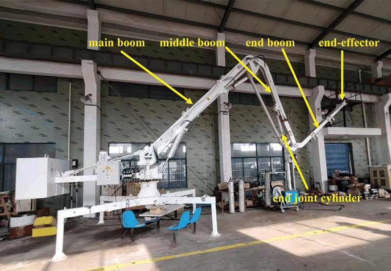
Figure 1 Concrete pump truck.
2 Studied System
The study focuses on a 4-DOF concrete pump truck which is a typical FHM, as shown in Figure 1. The concrete pump truck consists of a rotary motor, three joint cylinders, a main boom, a middle boom, and an end boom. The rotary motor controls the rotation of the concrete pump truck and the joint cylinders control the movement of the booms. This paper only focuses on the control of the end joint cylinder which can directly control the end-effector. The method is also applicable to other joints. The SVS and IMS are shown in Figure 2. Each hydraulic cylinder of the traditional SVS is controlled by a proportional directional valve, while the IMS has two proportional directional valves to control a cylinder. The IMS allows the system to have two independent signal inputs.

Figure 2 System structure.
3 Problem Statement
The DPF is widely used to reduce the vibration of hydraulic manipulators utilizing SVS. The load pressure is applied as a control input after passing through a high-pass filter. The key to applying DPF on asymmetrical cylinders is the selection of two parameters: the high pass filter gain and the time constant . Previously, the selection of parameters was highly dependent on engineering experience. Pedersen used the root locus method to analyze the selection of DPF parameters for symmetrical cylinders without position control [8]. However, in addition to achieving vibration reduction, the FHM also needs to keep the end-effector at a precise position. It requires adding position control to the system. The SVS has only one control input which cannot address the position control signal and the DPF control signal simultaneously. Meanwhile, there has been no previous research analyzing the design process and issues of DPF control combined with position control in SVS. To illustrate the problems caused by the interaction, the system combining the position and DPF control is first designed and analyzed.
The system model for valve-controlled asymmetric cylinders is well-known [11]. To simplify the analysis process, the hydraulic cylinder is assumed to be leakproof. The expression for the load pressure is obtained from the asymmetric cylinder characteristic as
| (1) |
The coefficients , and are
| (2) | |
| (3) | |
| (4) |
where is the cylinder velocity, is the opening of the valve, is the Laplace operator, and are flow coefficients, and are flow-pressure coefficients, is the bulk modulus, is the cylinder area ratio, and are the areas for two sides of the piston rod, is the volume ratio, and are the volumes of two chambers, is the ratio between valve opening gains, and are valve opening gains.
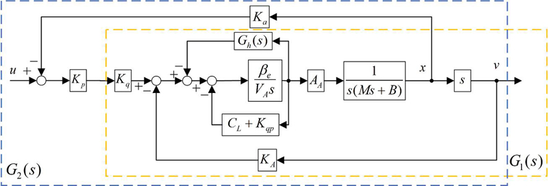
Figure 3 Transfer block of the SVS with the position control.
After adding the DPF control and the position control, the system can be represented in the block diagram form, as shown in Figure 3. The is the high pass filter, and is the combined leakage coefficient. The transfer function of the system without the position control can be obtained as
| (5) |
where is the position sensor gain, is the load mass, is the viscous damping, , , , , . It can be found that the variation of the system poles is related to and . The guidance for selection is that the high pass filter frequency is supposed to be set below the natural eigenfrequency of the original system [8].
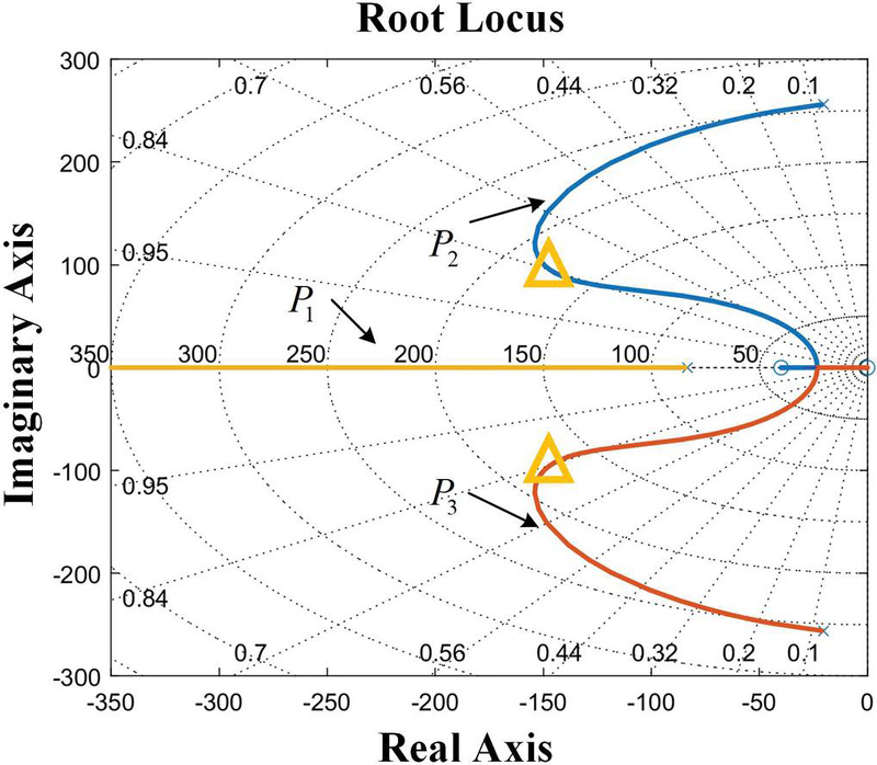
Figure 4 Root locus when varying (without position control).
Using the parameters listed in Table 1, a suitable value of 0.012 is selected in advance and the root locus can be obtained, as shown in Figure 4. The graph shows that the complex poles and are dominant. By choosing the points of the yellow triangle, with , the system can obtain a high damping ratio.
Table 1 Parameters of the SVS
| Parameters | Symbol | Value | Unit |
| Load mass | M | 250 | kg |
| Bulk modulus | 700 | MPa | |
| Cylinder area | m | ||
| Volume | m | ||
| Valve opening gain | m/V | ||
| Flow coefficients | m/s | ||
| Flow-pressure coefficients | m/(Pas) | ||
| Position sensor gain | 430 | V/m |
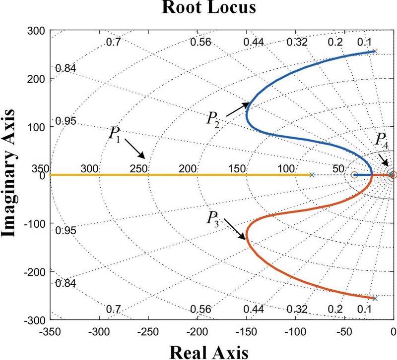
Figure 5 Root locus when varying K (with position control).
When the position control is added, the transfer function of the system with the position control can be expressed as
| (6) |
where is the proportional gain, , . Assuming , the root locus is shown in Figure 5. Compared to the previous system, a new pole is added. The pole is close to the imaginary axis and there is a zero at the origin of the coordinates. Therefore, they can achieve pole-zero cancellation and the complex poles and are still dominant. So the high damping ratio can be obtained in the same way as above.
However, the position control input and DPF control input are added directly to get the valve input in the SVS, as shown in Equation (7). When and have opposite signs, the effects of the two controls will cancel each other out. So the interaction of two control loops affects the performance of active damping control.
| (7) |
4 Control Design
In the past, many studies on the IMS mainly focused on improving energy efficiency [12–14]. However, they did not account for the effect of the IMS on the vibration control. To solve the above-mentioned problem of the control interaction, a decoupling active damping controller utilizing the IMS is designed, as shown in Figure 6. The system breaks the mechanical coupling of the inlet and outlet so that it can decouple the position controller and the DPF controller. It allows the two controllers to operate separately.

Figure 6 The transfer block of the IMS.
4.1 IMS Modelling
The dynamic characteristics of the system depend on the hydraulic cylinder and the proportional directional valve. Neglecting the valve dynamics, the flows through the valve are described as
| (8) | ||
| (9) |
where and are flow coefficients of the IMS, and are pressures of two chambers, and are flow-pressure coefficients of the IMS, and are control inputs of two valves. Using the continuity equation, the pressure in the two chambers can be described as
| (10) | |
| (11) |
where and are the bulk modulus of the chambers. The force balance of the hydraulic cylinder is given by
| (12) |
where is the load force. The transfer block of the IMS is shown in Figure 6. Since the FHM requires both the position control and the DPF control, the system has two outputs for position and pressure. In multivariable systems, different variable pairs have different decoupling effects. Assuming that controls the position and controls the pressure, the transfer function matrix of the system can be expressed as
| (13) | |
| (14) | |
| (15) | |
| (16) |
4.2 Analysis of the Interactions Between the Different Loops
To determine the best variable pair of the IMS, the RGA method is used to analyze the interactions between the different control loops quantitatively [15]. The RGA of a transfer function matrix is defined as
| (17) |
The elements of the RGA can be expressed as:
| (18) | |
| (19) |
where represents the gain from input to output with other control loops opening, and denotes the gain from input to output with other control loops closing. The relative gain is used to express the interactions between the different loops. If the relative gain is close to 1, it indicates minimal interaction between the loop from to and other loops. Therefore, the degree of coupling between different loops can be obtained by calculating the relative gain array. Based on the analysis above, the gain array can be determined as
| (20) |
Table 2 Parameters of the IMS
| Parameters | Symbol | Value | Unit |
| Flow coefficients | m/s | ||
| Flow-pressure coefficients | m/(Pas) | ||
| The bulk modulus of the chambers | 700 | MPa |
The relative gain is calculated as
| (21) |
When controls the position and controls the pressure, the relative gain is calculated to be 0.7075 by using the parameters listed in Table 2. Since this value is close to 1, it indicates that the interaction between the different control loops is minimal. On the contrary, if controls the pressure and controls the position, the relative gain is 0.2925, indicating greater interaction between the loops. So the best variable pair of the IMS is that controls the position and controls the pressure.
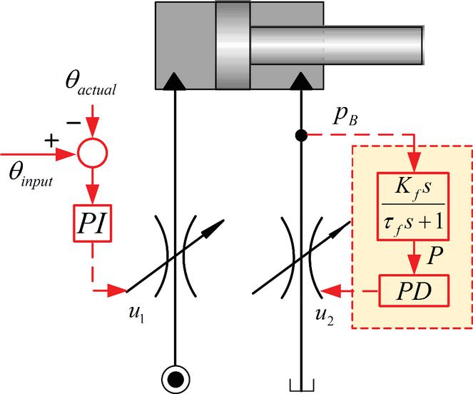
Figure 7 Decoupling controller schematic of position and pressure.
4.3 Decoupling Active Damping Controller Utilizing the IMS
To ensure positioning accuracy at the end-effector, position control is carried out at the meter-in valve, as shown in Figure 7. The control signal of the meter-in valve depends on the difference between the reference angle and the actual joint angle, as shown in Equations (22)–(23). Since requirements for the position control in the working process are mainly positioning accuracy, the PI controller is suitable for position control which the integral component can strive to eliminate steady-state error.
| (22) | |
| (23) |
where is the joint angle error of the end boom, is the target angle, is the actual angle, is the proportional gain of the position control, and is the integral gain of the position control. The meter-out valve is used for DPF control. The high pass filter extracts the pressure signal from the cylinder chamber and applies the signal to the meter-out valve through a PD controller, as shown in Equations (24)–(25). The PD control structure is a widely used control scheme in hydraulic manipulators. When the proportional component reduces the current error, the derivative component decreases the response time of the control as much as possible. The two control loops of position and active damping ensure the accuracy and stability of the hydraulic manipulator.
| (24) | |
| (25) |
where is the proportional gain of the DPF control, and is the differential gain of the DPF control.
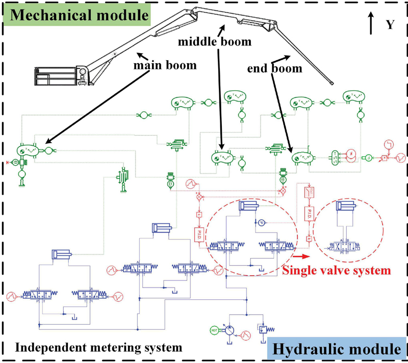
Figure 8 AMESim model of the concrete pump truck.
5 Simulation
5.1 Simulation Model
To validate the proposed method, a simulation model of the concrete pump truck is established in the AMESIM environment, as shown in Figure 8. The green parts are mechanical modules and the blue parts are hydraulic modules. The hydraulic system includes the establishment of both SVS and IMS structures. The main parameters are shown in Tables 1, 2, and 3. The model parameters for the hydraulic and mechanical modules remain the same in all of the following environments. Since the paper only focuses on the end joint, the directional valves of the first two joints are not operated.
5.2 Case Study of the SVS
This case study is to demonstrate the vibration reduction effect of the controller combining the position and DPF control based on the SVS. Firstly, the boom is stabilized, and then the external force N is applied to the end-effector within a short time. After manual adjustment of the position controller, the position control gain is selected as first and the vibration control parameters are selected in Section 3. The results are shown in Figure 9. To illustrate the influence of the control interaction, the position control gain is increased to 60. The results can be found in Figures 10 and 11.
Table 3 System parameters of the simulation model
| Parameters | Value | Unit |
| Maximum pump displacement | 30 | cm/rev |
| Pump rotational speed | 1440 | rev/min |
| Setting pressure of the relief valve | 25 | MPa |
| Stroke of the cylinder | 0.7 | m |
| Piston diameter | 0.08 | m |
| Rod diameter | 0.045 | m |
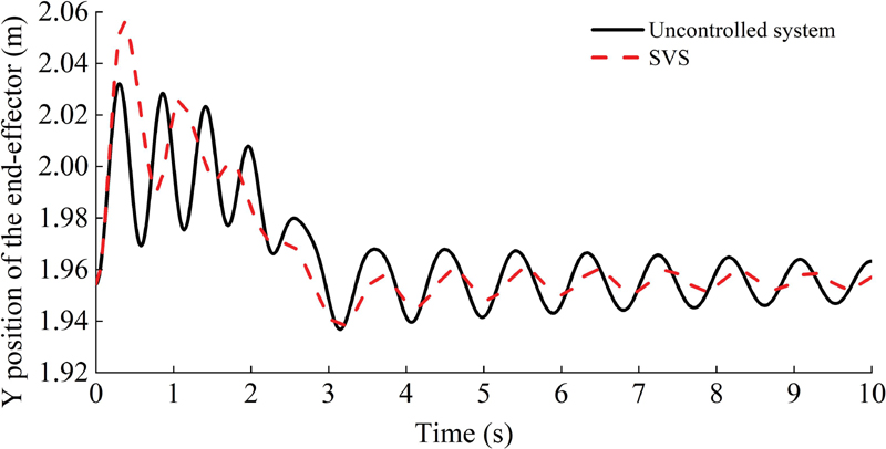
Figure 9 Y position of the end-effector utilizing the SVS.
When the external force is applied, the DPF control utilizing the SVS achieves vibration reduction. This is because the damping ratio of the system is improved by the root locus method. However, the Y position of the end-effector has a large overshoot when the boom is first subjected to an external force.
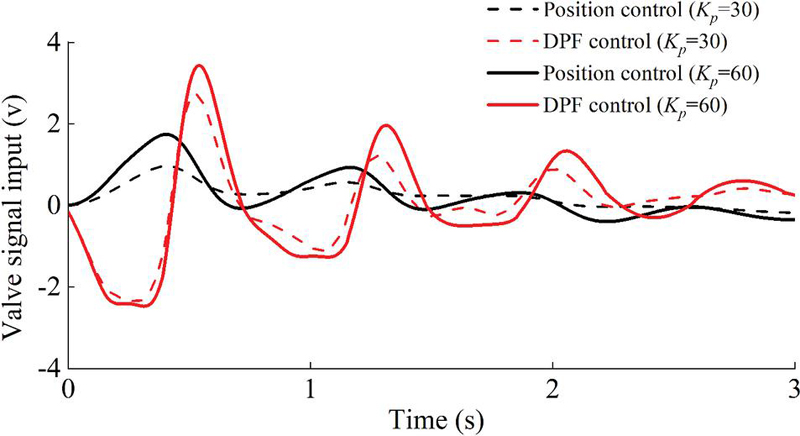
Figure 10 Valve signals of the SVS using different gains (position control gains: and ).
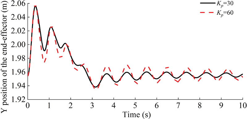
Figure 11 Y position of the end-effector using different gains with SVS (position control gains: and ).
When the position control gain is 30, the position control signal and the DPF control signal are sometimes opposite signs. It will cause the effects of the two controls to cancel each other out. In addition, if the position control gain increases from 30 to 60, the DPF control signal is obviously changed and the vibration of the end-effector increases significantly. The interaction between the position control and the DPF control affects the vibration control capability.
5.3 Case Study of the IMS
As with the SVS simulation, the external force N is applied to the end-effector in the IMS. Position controller parameters are the same as SVS simulation and the results are shown in Figure 12. Similarly, to show the interaction between the two control loops, position control gain is adjusted from 30 to 60. The results of the valve input signal and the vibration can be found in Figure 13, and Figure 14.
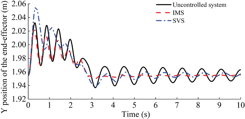
Figure 12 Y position of the end-effector utilizing the IMS.

Figure 13 Valve signals of the IMS using different gains (position control gains: and ).

Figure 14 Y position of the end-effector using different gains with IMS (position control gains: and ).
Compared to the SVS control method, the maximum vibration of the proposed method is reduced by 20%. Meanwhile, with the increase of the position control gain, the DPF control signal does not change significantly and the vibration of the end-effector shows little variation. The proposed method reduces the interaction between two control loops. It also makes the control parameters have a wider adjustment range than the traditional method.
6 Conclusion
This paper analyzes the coupling problem of the controller combining the position and DPF control based on the SVS. Then a decoupling active damping controller based on the IMS is designed to solve this problem. The proposed method is designed by the RGA method which determines the best variable pair of control loops. The simulation results indicated that, compared to the SVS control method, the proposed method has a wider range of control parameters and improves vibration reduction performance by 20%. In the future, the controller parameters will be selected through optimization algorithms to improve controller performance.
Acknowledgment
This work was supported by the National Natural Science Foundation of China (Grant No.U21A20124), the Key Research and Development Program of Zhejiang Province (No.2022C01039), and the National Natural Science Foundation of China (Grant 52175050).
References
[1] R. Rahmfeld and M. Ivantysynova, “An overview about active oscillation damping of mobile machine structure,” International Journal of Fluid Power, vol. 5, no. 2, pp. 5–24, 2004.
[2] M. Axin and P. Krus, “Design rules for high damping in mobile hydraulic systems,” in 13th Scandinavian International Conference on Fluid Power, pp. 13–20, 2013.
[3] J. Henikl, W. Kemmetmueller, T. Meurer, and A. Kugi, “Infinite-dimensional decentralized damping control of large-scale manipulators with hydraulic actuation,” Automatica, vol. 63, pp. 101–115, Jan 2016.
[4] F. Zhang, J. Zhang, B. Xu, and H. Zong, “An Adaptive Robust Controller for Hydraulic Robotic Manipulators with a Flow-Mapping Compensator,” International Journal of Fluid Power, vol. 22, no. 2, pp. 259–276, 2021.
[5] F. Zhang, J. Zhang, M. Cheng, and B. Xu, “A Flow-Limited Rate Control Scheme for the Master-Slave Hydraulic Manipulator,” IEEE T Ind Electron, vol. 69, no. 5, pp. 4988–4998, May 2022.
[6] M. Cheng, S. Luo, R. Ding, B. Xu, and J. Zhang, “Dynamic impact of hydraulic systems using pressure feedback for active damping,” Appl Math Model, vol. 89, pp. 454–469, Jan 2021.
[7] A. Alexander, A. Vacca, and D. Cristofori, “Active vibration damping in hydraulic construction machinery,” in 3rd International Conference on Dynamics and Vibroacoustics of Machines (DVM), Samara, RUSSIA, vol. 176, pp. 514–528, 2016.
[8] H. C. Pedersen and T. O. Andersen, “Pressure Feedback in Fluid Power Systems-Active Damping Explained and Exemplified,” IEEE T Contr Syst T, vol. 26, no. 1, pp. 102–113, Jan 2018.
[9] A. H. Hansen, H. C. Pedersen, T. O. Andersen, and L. Wachmann, “Investigation of energy saving separate meter-in separate meter-out control strategies,” in 12th Scandinavian International Conference on Fluid Power, 2011.
[10] C. Williamson, S. Lee, and M. Ivantysynova, “Active vibration damping for an off-road vehicle with displacement controlled actuators,” International Journal of Fluid Power, vol. 10, no. 3, pp. 5–16, 2009.
[11] J. Watton, Fundamentals of fluid power control. Cambridge University Press, 2009.
[12] R. Ding, J. Zhang, B. Xu, and M. Cheng, “Programmable hydraulic control technique in construction machinery: Status, challenges and countermeasures,” Automat Constr, vol. 95, pp. 172–192, Nov 2018.
[13] R. Ding, J. Zhang, and B. Xu, “Advanced energy management of a novel independent metering meter-out control system: A case study of an excavator,” IEEE Access, vol. 6, pp. 45782–45795, 2018.
[14] B. Xu, J. Shen, S. Liu, Q. Su, and J. Zhang, “Research and Development of Electro-hydraulic Control Valves Oriented to Industry 4.0: A Review,” Chin J Mech Eng, vol. 33, no. 1, Apr 1 2020.
[15] S. Skogestad and I. Postlethwaite, Multivariable feedback control: analysis and design. Citeseer, 2007.
Biographies

Ruiheng Jia received the B.S. degree in mechanical engineering and automation from China University of Petroleum, Qingdao, China, in 2021. He is currently working toward the Ph.D. degree in the College of Mechanical Engineering, Zhejiang University, Hangzhou, China. His research interests include flexible hydraulic manipulator control and vibration suppression.

Junhui Zhang received the Ph.D. degree in mechatronics engineering from Zhejiang University, Hangzhou, China, in 2012. He is currently a Tenured Associate Professor with the Institute of Mechatronic Control Engineering, and the Deputy Director of the State Key Laboratory of Fluid Power and Mechatronic Systems, Zhejiang University. He has authored or coauthored more than 80 papers indexed by SCI and applied more than 30 National Invention Patents with granted. He is supported by the National Science Fund for Excellent Young Scholars. His research interests include high-speed hydraulic pumps/motors, heavy-duty hydraulic manipulators and hydraulic quadruped robots.

Ruqi Ding was born in Nanchang, China, in 1987. He received the B.S. degree in mechatronics engineering from Nanchang University, Nanchang, in 2009, and the Ph.D. degree in fluid power transmission and control from Zhejiang University, Hangzhou, China, in 2015. He is currently a Professor with the Key Laboratory of Conveyance and Equipment, Ministry of Education, East China Jiao tong University, Nanchang. His research interests include electrohydraulic control systems and the motion control of hydraulic manipulators.

Fu Zhang received the B.Eng. degree from Jilin University, Changchun, China, in 2018. He is currently working toward the Ph.D. degree in the College of Mechanical Engineering, Zhejiang University, Hangzhou, China. His research interests include hydraulic robot control and trajectory planning.

Jun Shen was born in Jiujiang, China, in 1995. He received the B.S. degree in mechanical engineering and automation from Wuhan University, Wuhan, China, and currently he is working toward the Ph.D. degree in the College of Mechanical Engineering, Zhejiang University, Hangzhou, China. His research interests include nonlinear controller design of hydraulic systems, cooperative hydraulic manipulators, advanced hydraulic actuators and relative hardware circuit design.

Bing Xu received the Ph.D. degree in fluid power transmission and control from Zhejiang University, Hangzhou, China, in 2001. He is currently a Professor and a Doctoral Tutor with the Institute of Mechatronic Control Engineering, and the Director of the State Key Laboratory of Fluid Power and Mechatronic Systems, Zhejiang University. He has authored or coauthored more than 200 journal and conference papers and authorized 49 patents. Dr. Xu is a Chair Professor of the Yangtze River Scholars Program and a Science and Technology Innovation Leader of the Ten Thousand Talent Program.
International Journal of Fluid Power, Vol. 25_2, 163–182.
doi: 10.13052/ijfp1439-9776.2523
© 2024 River Publishers