Design of a Lead-Free Slipper Bearing for Low Speed Axial Piston Pump Applications
Roman Ivantysyn, Svenja Horn* and Jürgen Weber
Institute of Mechatronic Engineering, TU Dresden, Germany
E-mail: roman.ivantysyn@tu-dresden.de; svenja.horn@tu-dresden.de; juergen.weber@tu-dresden.de
*Corresponding Author
Received 29 May 2024; Accepted 03 June 2024
Abstract
New application areas for hydrostatic machines result in novel challenges for the fluid film performance of the lubrication interfaces. In the past hydrostatic machines were designed with a combustion engine or a constant speed electric motor in mind. Therefore, they typically have a minimal speed requirement and are optimized for a low variation in their operating speed range. Electrification and flow by demand change this requirement drastically, forcing the pumps often in both very high and very low operating speeds. Typically, lubricating gaps in positive displacement machines consist of a hard/soft material pairing, where the soft pairing usually is a yellow brass with variable lead content. The lead is added to allow for mix friction contact at low speeds and other critical conditions. New developments in surface structuring allow for precise manufacturing of the surface shaping in the sub micro-meter range. This paper combined this technology with state of the art numerical simulations to design a surface structure that is capable withstanding pump operations without significant wear and therefore allows for lead free materials – even steel/steel pairings. The different materials were tested in simulation, on a novel hydrostatic-tribometer test rig as well as on the pump test rig. The design process as well as the simulation and measurement results will be presented in this paper.
Keywords: Axial piston pump, slippers, surface structures, lubricating gap, numerical simulation, tribology, lead-free material, wear, run-in.
1 Introduction
Positive displacement machines used in mobile applications are forced to go through a paradigm shift in respect with their operational regime. In the past hydraulic pumps were attached to diesel engines, which have a specific speed range for which the pumps were optimized. In the near future, many mobile machines will be powered by electric motors. Not only can these motors spin at much higher speeds, but they also have no problem turning at very low speeds with high torque. This means that hydrostatic pumps will need to be able to operate well in these low-speed conditions as well.
Unfortunately, most hydrostatic pumps are highly reliant on hydrodynamic pressure built up in their lubricating gaps. For example, the slipper in axial piston pumps uses a hydrostatic and hydrodynamic bearing to support the load exerted by the piston. Figure 1 illustrates a cross section of such a piston pump. Looking at the highlighted parts it becomes apparent that a combination of steel and copper-alloy materials form each lubricating gap. The use of brass or bronze is very common for high pressure pumps. These pumps usually go through a run-in phase, where surface shape and topology changes. The softer material allows for a gentler wear of the parts, without running into the risk of friction welding them together. Another benefit of brass is that it typically contains lead, which has an excellent dry-running operation property. However, due to health and environmental factors law-makers try to ban lead containing materials from consumer products. Today, pumps still allow a certain percentage of lead in their materials, but most pump manufacturers are trying to find alternative materials to be ready if an ultimate ban would become law.
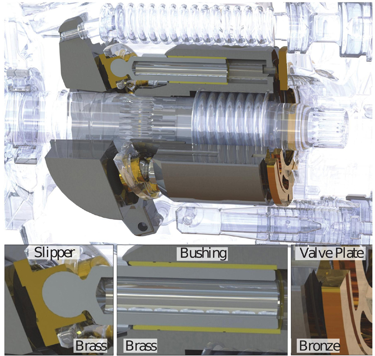
Figure 1 Cross section of an axial piston pump.
Summarized, machine requirements push for lower speed regimes and more frequent halts of the pump, while law makers try to ban the materials that allow pumps to withstand mixed friction conditions, which occurs more frequently at low speed.
2 Research Goal and Approach
The research goal was to develop a robust low speed, low wear, high-performance lead-free slipper using surface optimizations. The general idea is that in order to push lead out of pumps, mixed friction first needs to be avoided. Fortunately, axial piston pumps have hydrostatic bearings, which allow for full lubrication and low viscous friction, by adjusting the pocket and sealing land ratios. Unfortunately, there is also hydrodynamic pressure built up that needs to be accounted for at high speeds, which forces the pump designer to reduce the hydrostatic force to avoid high gaps and resulting high leakage. On the other hand, hydrodynamics help to generate a lubricating gap at start up and low pressure conditions. Traditional slipper design approaches, such as changing the pocket size, sealing land width or orifice, usually put the designer at a choice, either having a well performing slipper at low speeds and low pressures or having optimal powerlosses at high speeds and high pressures, but usually not both. Surface structures allow for more degrees of freedom in the design of the gap. Not only can they increase pressure built up at lower speeds, they also can alter the pressure distribution across the sealing land, generating a more stable and uniform seal. For this research multiple slipper designs were studied using a sophisticated simulation tool, Caspar FSTI. It has been validated in previous research projects [1] and has proven to be a very reliable design tool. Three designs were selected to be manufactured, with the best design to be also built in a lead-free metal. This paper presents the measurement results, the low speed behavior as well as the material wear of these design variations on a pump test rig.
3 Literature
There are three ways to avoid wear in hydrostatic bearings:
1. Increase hydrostatic lift
2. Increase hydrodynamic lift
3. Reduce friction in case there is metal to metal contact (surface treatment)
Adding hydrostatic pockets to increase lift is commonly done in bearings that have to withstand high loads and low speeds. However, these usually add leakage and reduce performance. Axial piston pumps already are hydrostatically compensated therefore it is not common to add additional pockets. Achten did add extra pockets to the cylinder block sealing gap, they are controlled by small orifice limiting the leakage. These orifices are difficult to manufacture as they have to be very precisely shaped as small deviations increase the power loss exponentially [2]. When manufactured correctly the pump or motor can have very good low speed performance. Haug introduced additional hydrostatic bearings that were valve controlled to allow for an adjustable compensation [3]. While promising the added number of components likely won’t be adopted by industry due to additional costs.
In the past there have been numerous publications with the topic of increasing hydrodynamic pressure built up, for example in journal bearings or in combustion engines [4, 5]. However, adapting these micro dimples to hydrostatic bearings in axial piston pumps is not possible, as the micro structures are too deep and localized and therefore change the hydrostatic behavior drastically [6]. Meso-structures in wave form, meaning the depth to length ratio is in the order of 1:1000 or more, have shown to be effective on the cylinder block before, as they increased low speed performance and reduced wear of a valve plate [7]. These wave-like features have therefore been chosen to also be adapted onto the slipper.
If mixed friction cannot be avoided surface coatings are means to reduce torque losses by reducing the friction coefficient. Rizzo for example has coated the slippers of a pump and was able to reduce the friction coefficient by almost half [8]. The problem with surface coatings is, that they don’t prevent metal to metal contact, but rather reduce the friction and possibly wear during contact. During low pressure contact these coatings are possible to withstand the normal forces, but during high pressure contact the normal forces can exceed several tons and can lead to wear of the coating [9]. Hence a slipper should be designed with the lowest possible wear and then a coating could help to further reduce friction. To replace brass or bronze with lead-free copper alloys has gained more attention recently. The problem is that it is not fully understood why brass and bronze have such a positive effect on the lubricating gaps. Some believe it is due to their softer nature, making it easier for the geometry to wear into a more optimal shape and allowing for larger manufacturing tolerances. But this would not explain why lead has such a benefit. Others reason that lead containing brass forms a special surface after the initial contact, forming a low resistant and robust surface topology. It is probably a combination of the two reasons, as Haidarshin found out. She showed that tribometer tests with lead-free copper alloys behave completely differently than performance tests in pumps [10]. Showing that simply swapping a leaded copper alloy with a nonleaded probably won’t work. However, this paper will show that designing a slipper with low wear allows for such a swap.
4 Simulation Results
4.1 General Approach
The simulation tool Caspar FSTI was used for the design of the slipper. The model was validated in previous publications for this pump for a single land slipper design using temperature and gap height measurements [1, 11]. The test pump was an open circuit pump Parker PV series (92 cc). The slipper of this pump has a multi-land design, which is not optimal for surface structures. Hence, a new single land slipper was designed solely in simulation. The outer diameter was decreased to 29.6 mm to reflect the mean of five leading pump manufacturers. This ensures are broader scope of the results as the flat single land slipper servers as a baseline and represents the very best possible single land design for this given piston size (21 mm diameter). The pitch diameter of the pump is 92 mm, the presented results will also be applicable to larger or smaller pump sizes, they will just need to be scaled. The influence of the pitch diameter for the slipper losses can be seen in Figure 2. Shown are the differences with respect to 92 mm. The smaller the pitch the lower the expected losses for some operating conditions (OCs). The next section explains these OCs in more detail.
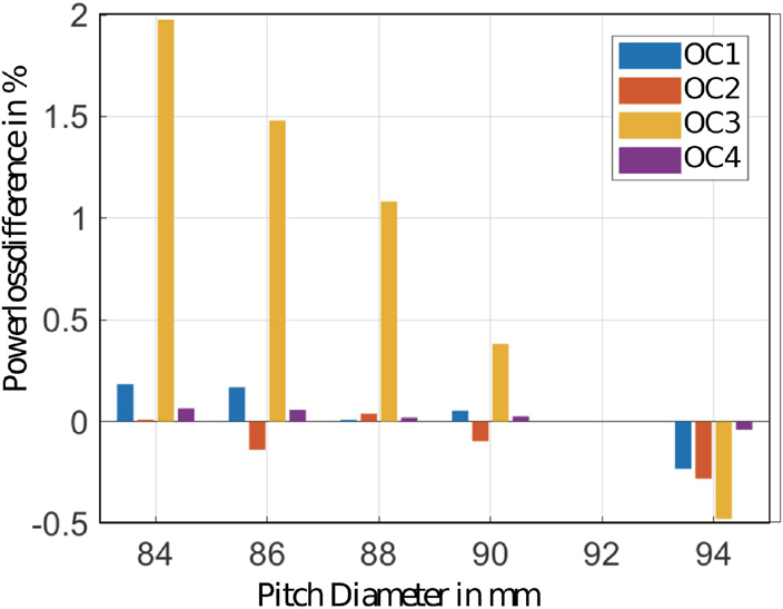
Figure 2 Influence of the pitch diameter on the powerlosses at different operating conditions (OCs).
4.2 Selected Operating Conditions (OCs)
Pumps need to be able to operate in a wide span of operating conditions, but optimizations require a hundreds of simulations. To reduce the required simulation numbers, four OCs were chosen to represent the entire operational regime. Table 1 shows the selected four OCs inducing critical conditions in the operation of a pump. OC1 with low speed and low working pressure represents start-up or idle situation. During these conditions it is most likely that mixed friction and abrasion can occur due to insufficient hydrodynamic pressure built up. OC2 with low speed but high pressure is typical for load holding situations in low flow conditions, a typical condition for high leakage losses, which need to be prevented. OC3 represents high speed low power applications. Low pressure and low displacement angle provoke lift off and possible high leakage losses. Maximum power output occurs at OC4 which represents a very significant OC for the OEMs and their customers. 1800 rpm was chosen even though the pump can spin to 2300 rpm, it represents a more average max speed around the industry and was chosen to avoid any potential cavitation problems that may occur at the maximum self-priming speed of the pump. During testing no such effects were discovered, hence test results show measurements up to 2300 rpm.
Table 1 Definition of operating conditions (OCs)
| OC | n [rpm] | p [bar] | [%] | Represents |
| JK11 | 500 | 50 | 100 | Idle |
| JK22 | 500 | 350 | 100 | Low flow high load |
| JK33 | 1800 | 50 | 20 | Prevent slipper lift-off |
| JK44 | 1800 | 350 | 100 | Maximum power |
4.3 Material Study
The primary goal was to design a well working low speed slipper, without sacrificing performance at high speed and high pressure. The secondary objective was to design a slipper that has minimal wear and could therefore be tested with a lead-free material. The simulation tool can predict the effects of material properties, such as density, Young’s Modulus, thermal deflection, and the poisons ratio on the performance of the slipper. In a case study brass, bronze, steel and four different lead-free alloys were tested. Figure 3 left shows the sum of the powerlosses across all four OCs for a given design. There are minor differences between the metals, especially the soft bronze material performs very poorly in slipper applications. This is probably why it is mainly used for valve plate coatings or bushings.
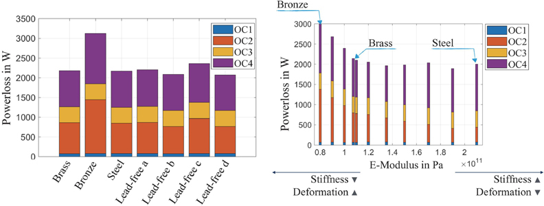
Figure 3 Sum of the powerlosses of the 4 OCs for different materials (left) and a rising Youngs Modulus (right).
The reason for the differences of the materials is mainly due to the stiffness of the material, represented by Young’s Modulus or E(lastic)-Modulus as can be seen in Figure 3 right. Below a certain stiffness the deformation of the slipper is too high and can therefore affect the performance especially at high pressures (OC2 and 4).
4.4 Final Designs
Each design was limited to an outer diameter of 29.6 mm, as described in Section 4.1. All other parameters were free to choose for the optimization. For the reference slipper a flat single land design was set as a requirement. Two main surface structures emerged as most promising. A waved design, comparable to the waved structure in [12] and a novel step like structure. The final dimensions for each design are shown in Figure 4. A detailed description of the development of the designs and the optimization process is given in [13]. Each design features a different pocket size and therefore balance factor (B). The balance describes the ratio of piston force acting on the slipper divided by the hydrostatic force. This analytical factor is widely used in industry to describe hydrostatic bearing designs. The simulation shows a great improvement of the low speed performance (OC1) without a significant efficiency decrease at higher speeds and pressures, which was the aim of this study. A more detailed analysis of the simulation results can be found in [13].
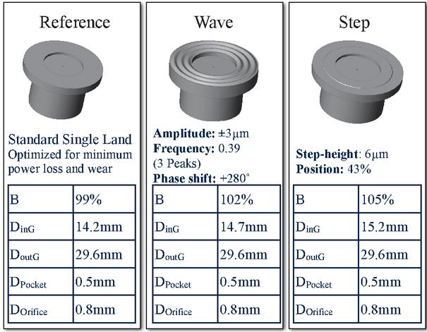
Figure 4 Final optimized designs.
5 Measurement Results
5.1 Overview of the Manufactured Slipper Designs
A total of 5 slipper designs were tested on the pump test rig: Standard multi-land, reference, wave, step, step (lead-free). Each design went through a series of steady state measurements with varying speeds (500–2300 rpm), pressures (0–350 bar) and displacements (25–100%) for a total of 144 operating conditions (OCs). Each set was repeated multiple times. Between the measurements of the 144 OCs also ultra-low speed tests were performed. The tests were repeated until no longer changes in efficiency were measured, allowing for the assumption that the run-in process is completed. The machining of the slippers was performed at the Fraunhofer IWU, Chemnitz. Multiple machining methods were studied with the goal to be able to propose mass producibility of the structured slipper. The following processes were proposed: turning, turning and rolling, turning and diamond deburring, and stamping. For the pump test the surfaces were purely turned, where the precision was achieved utilizing a piezo-actuated cutting head. This led to a step-like profile of the wave and a step like gradient between the sealing planes of the step slipper, shown below in Figure 5. The step profile of the wave was simulated and compared to a smoother shape. The results indicated that it made no noticeable difference, more important was that the maximums and minimums are located correctly. More tests will be performed on a hydrostatic tribometer to analyze differences in the manufacturing techniques with respect to performance and wear. Very promising seemed the results in the stamping process, demonstrating that it is very feasible, accurate and repeatable. While the reference slipper was lapped, as are all components in the rotating kit of axial piston pumps, the wave and step slipper were turned only, but obviously to a high precision as shown in the bottom of Figure 5. This means that the time-consuming lapping process can be avoided by using micro-structures.
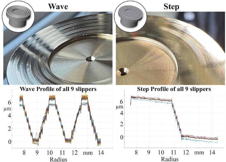
Figure 5 Manufactured slippers with micro-surface shapes and their surface profiles before measurements.
The next section shows the surface profiles for each slipper after multiple hours of operation including ultra-low speed operation. While this article focuses on wear and torque losses, the step slipper also achieved major improvements on the overall efficiency of the pump. Those efficiency improvements along with the detailed design process can be found in [14].
5.2 Run-in of the Reference Slipper
After an initial run-in (8 hours) with the standard components and the multi-land slipper, the pump was disassembled and reassemble with the single land reference slipper by a professional Parker engineer. After 35 hours of testing the pump was disassembled and slipper revealed a change in color indicating that there was material abrasion. The reference before and after testing is shown in Figure 6. The surface scan shows micro scratches from the lapping process, those nearly disappeared after the test, but the deepest ones are still visible. The bottom of Figure 6 shows the profilometer measurements, which indicate that slipper shaved off the peaks and became very smooth, more than halving its surface roughness.
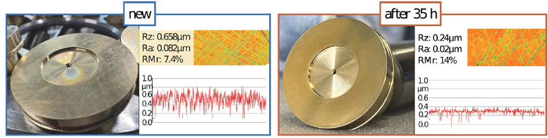
Figure 6 Reference slipper surface roughness before testing (left) and after 35 h (right).
The change of the overall shape can be seen in Figure 7. Unfortunately, it is not possible to measure the absolute wear amount as there is no reference point on the flat slipper to compare both curves. All nine slipper surfaces were measured four times, the shown curves are the minimal curve of the worn slipper and the maximum curve of the new slipper. As the profilometer has absolute tolerance of 1 m in the height the curves show the worst case wear. The actual slipper wear will be within that range. The wear profile indicates that the material wear is higher at the inner edge of the slipper than at the outer edge. This can be confirmed by visual inspection of the slippers.
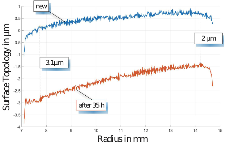
Figure 7 Overall profile shape of the reference slipper before and after 35 hours of testing.
The performance of the reference slipper can be summarized as very good. The efficiency is equal or greater compared to the multi-land slipper even though it has a smaller diameter (0.9 mm) it is assumed it could achieve an even better performance with a larger diameter (more surface area). The wear is minimal, but as indicated by the color change occurs across the entire sealing land.
5.3 Run-in of the Waved Slipper
The waved slipper design is shown in Figure 5 on the left. It is a step like sine wave with a peak-to-peak amplitude of 6 m. The design was derived from numerous simulations varying amplitude, phase and frequency, see [13]. The performance of the wave slipper was very good, especially at low speed and low pressure as expected by simulation. A four percentage-point gain (from 83% to 87% see Figure 10) of the total pump efficiency was achieved at OC1 while at OC3 (20% displacement) an overall gain of 11 percentage points was measured. It produced slightly higher leakage while improving torque loss by more than 50%. The full results can be found in [14, 15].
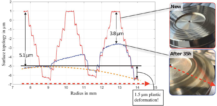
Figure 8 Wave slipper surface profile (left) and photos (right) before and after 35 h of testing.
After 35 hours of testing the slipper was inspected and the result is shown in Figure 8. At first glance it was visible that the profile was still present but with clear wear marks. The profilometer measurements, shown at the bottom of the figure, indicate that the peaks of the wave have worn off almost completely at the inner edge of the slipper land, and up to 3.8 m at the outer edge. The valleys of the profile are still present and give a clear reference how much material was removed. Since the valleys of the worn profile are not on the same level as the new slipper, plastic deformation must be assumed in the order of 1.5 m. The performance of the slipper was improving with time, suggesting that the surface will not wear any further. This was confirmed by 565 hours accelerated lifetime tests, here the wave slipper showed similar marks as the after 35 hours, therefore the structure will not wear in further.
5.4 Run-in of the Step Slipper
The step design slipper is shown on the right of Figure 5. It is a very simple design of a 6 m step located at 46% of the length of the slipper sealing land length. The design was derived from studies made with variable frequency waves. It was shown that a high number of peaks at the inner radius and a low number of peaks at the outer radius is more beneficial than a constant frequency of the wave. Along with analytical calculations and many other simulation studies the step design was born. It is not very intuitive, as shown in Figures 7 and 8 the typical wear profile shows that more material is worn off at the inner edge of the slipper. Adding more material at this spot seems counter intuitive. That is probably why this kind of design has not been discovered yet. The performance of the step slipper was better than the waved surface at low speed and low pressure and better than the reference slipper at high speed and high pressure. Six percentage points improvement in the total efficiency at OC1 was measured (see Figure 10), and up to 25 percentage points improvement at 20% displacement, while not losing any performance at high speed or pressure.
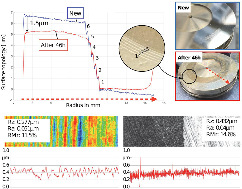
Figure 9 Step slipper after 46 hours of testing.
Figure 9 shows the step slipper before and after 46 hours of testing. The step design had virtually no run-in. Even after 46 hours of rigorous pump testing the 6 m step had only shaved of 1.5 m at the inner diameter, which is in the surface roughness tolerance. 5 of the 6 steps are still visible and the outer sealing surface shows no wear marks, as indicated by the different color. As shown by the profilometer the Ra value, which indicates average roughness is even lower than the already very good initial condition. The RMr indicates how many peaks are below a certain limit of the mean. The higher the number the less profound are the peaks, e.g. the smoother the surface. Essentially the step slipper just wears down the peaks. Another indicator are the radially outflowing skid marks, probably formed by micro metal debris in the oil. The test rig has a 4 m filter installed, which means that the gap must have been well below this gap height to form these marks, confirming the simulated gap heights of 2–6 m.
5.5 Lead-free Slipper Efficiency Measurements
After inspecting the step slipper, it was clear that there was very low wear. Therefore, the authors felt confident to install a lead-free alloy slipper with the same step design (compare to “lead-free d” in Figure 3). This slipper was tested for efficiency in steady state and ultra-low speed conditions and for endurance in a 565 hours accelerated condition test at the pump manufacturers test facility. Figure 10 shows the measured total efficiency for all tested designs at full displacement angle. All designs went through a run-in phase, which improved their efficiency. As the structured slippers were turned, their surface roughness was higher than a lapped surface, which decreases performance at low gap heights. The run-in process for the step merely smoothened the surface as can be seen in Figure 9. Due to due time constraints the lead-free slipper was tested only for 10 hours. As the brass step slipper took about 30 hours to reach peak efficiency especially at high pressure and low speed, it is expected that the lead-free step slipper did not complete its run-in process yet. Nevertheless, it outperformed the reference and wave at almost every operating point and even surpassed the efficiency of the brass step slipper at low pressures. At high pressures the gap height of the step slipper is very small, which results in an excellent volumetric efficiency, which is slightly lower for the lead-free slipper due to its surface roughness. It is to be expected that the lead-free slipper will also wear in and increase its volumetric efficiency at as the brass step slipper showed similar efficiency after 10 hours of testing at high pressure.
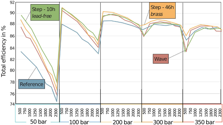
Figure 10 Efficiency of the lead-free and brass step slipper after 5 and 10 hours (0 and 45 hours respectively), compared to the reference.
If the lead-free slippers do not experience the same kind of wear-in of the peaks, it could be considered to first perform a lapping process and then machine the 6 m step. This could improve efficiency but would also add an additional manufacturing step, that is not necessary with the brass step slipper. Both the lead free and leaded material in step design showed no further wear after 565 hours of endurance testing [15], confirming that the step design is indeed long lasting, which paves the way for completely lead-free materials.
5.6 Performance at Extremely Low Speeds
Figure 11 (left) shows the torque loss for the entire axial piston pump at cold conditions for low speeds from 0.1 to 20 rpm. The pump has been off for at least 24 hours and the oil is at room temperature (T 18C). Shown is the measured torque for the reference, wave and step design. The step design is shown in three variations, brass after 10 hours, brass after 45 hours and lead-free alloy (about 5 hours). The curves have been repeated for all designs multiple times but are not all shown. The low speed torque is significantly lower for all step designs compared to the reference slipper, the lowest being the lead-free slipper. The start-up torque at 1 rpm is 80% lower for the lead-free step design compared to the reference design. All pumps with step slipper designs exhibit ultra-low torque losses between 4 and 10 rpm, where the torque meter read 0.01 Nm. For the lead-free this extends to 100 rpm. The pump runs in this operating regime virtually resistance free. What’s astonishing is, that this is only due to the change in slippers.
The start-up torque in warm oil conditions is shown in Figure 11 (right). The speed is shown from 0.1 rpm to 1000 rpm on a logarithmic scale. The reference slipper experiences minimum torque loss between 50 and 200 rpm. Below 50 rpm the torque loss steadily increases. The wave slipper allows the pump to decrease this minimum torque speed to 10 rpm, then torque loss increases. The step slipper further decreases this minimum to 5 rpm. More importantly even at 0.1 rpm the torque loss is still less than half than the reference at 1 rpm.
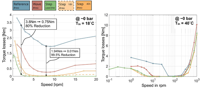
Figure 11 Start-up torque loss at cold (left) and warm (right) oil conditions and for various slipper designs.
At 50 bar working pressure the wave and step design experience similar torque losses, both with more than 80% peak reduction compared to the reference slipper, compare Figure 12 (left). The minimum torque loss is also shifted towards the lower regime. The reference slipper has its lowest torque loss at 100 rpm, while the wave and step slipper hit the minimum at half of that, 50 rpm. This clearly shows that surface structures can greatly enhance ultra-low speed performance, which is necessary for load holding and reversal applications with electromotors such as compact drives. While the waved slipper has similar torque losses, it experiences a much higher leakage at these conditions, as shown in Figure 12 (right). In contrast the step slipper, both in its brass and lead-free configuration have a lower leakage than the reference slipper.
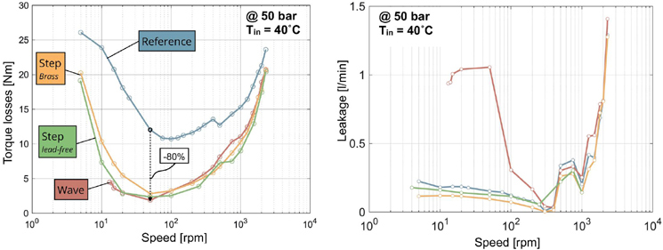
Figure 12 Torque loss (left) and leakage (right) at 50 bar and 40C inlet temperature.
At 300 bar working pressure the step slipper experiences similar torque losses as the reference slipper as illustrated in Figure 13. The wave slipper exhibits as a much flatter curve, staying between 16 and 18 Nm all the way from 30 rpm to 500 rpm. This torque loss could be very beneficial for example for motor applications, if the leakage of the waved slipper could be reduced.
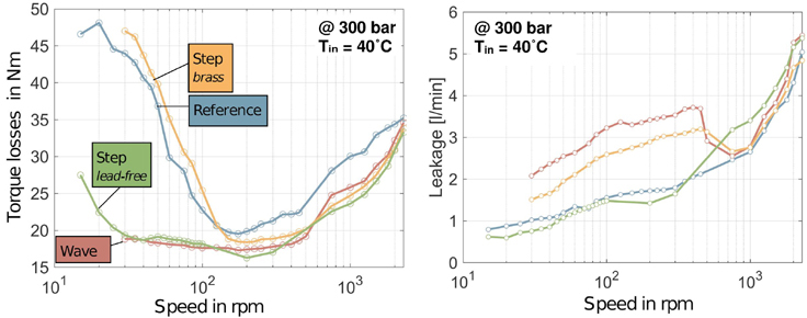
Figure 13 Torque loss (left) and leakage (right) at 300 bar and 40C inlet temperature.
6 Summary and Conclusion
Low speed applications will become more popular with time. Preparing hydrostatic machines for this task is even more of a challenge considering that lead containing metals, such as brass and bronze, will be banned due to environmental reasons in some countries in the near future. Surface structures in the meso-regime, meaning small changes in height over a large distance, could be one solution to the problem. In this paper two surface structures were introduced. The first is a wave like pattern with a 6 m peak-to-peak amplitude. The second is a 6 m step, removing material from the outer sealing land of a slipper. Both designs were compared in simulation and measurement to an optimized single land slipper design. All designs experienced a low material wear, and performed well across all operating conditions. The wave structure experienced the most amount of wear, but stabilized with about half of the wave still intact. With the wave structure low speed and low pressure applications had a much better efficiency and torque loss than the flat reference slipper. At high pressures this leakage increased. This leakage could probably be improved upon with further simulations. The new step like structure has shown tremendous results. Not only was the wear strongly reduced to the inner edge of the slipper, but the pump with the step slipper performed by far the most efficient in all operating points. At ultra-low speeds the cold and warm start up required up to 80% less torque and maintained this torque advantage all the way to high speeds. The low amount of torque and wear enabled this slipper design to be manufactured with a lead-free copper alloy and first results show the same great performance as the brass slipper. A cyclic 565 hours endurance test under elevated pressure was completed for all designs. The visual inspection shows that both structures are still intact and all steps are visible. The quantitative profilometric analysis confirms the lowest wear with a maximum of 1 m on the inner radius for the lead-free slipper. The brass slipper wears off up to 1.5 m on the inner radius. The step design will soon be tested in a steel/steel pairing, to further test its capabilities. This could eliminate the need for copper alloys completely for future pumps, increasing cost effectiveness and life time.
Acknowledgment
The presented research activities are part of the project “Tribologieoptimierung von Pumpensystemen durch fertigungsgerechte Einbringung von Mesostrukturen” (Ref. No. 20757 BR/1). The authors would like to thank the Fluid Power Research Fund of the VDMA for the funding and support.
References
[1] R. Ivantysyn, A. Shorbagy, and J. Weber, “Investigation of the Wear Behavior of the Slipper in an Axial Piston Pump by Means of Simulation and Measurement,” in 12th IFK, 2020.
[2] P. Achten, R. Mommers, J. Potma, and J. Achten, “Experimental Investigation of a Hydrostatic Bearing Between Barrels,” in BATH/ASME, FPMC 2020, 2020
[3] S. Haug: “Optimization of Axial Piston Units Based on Demand-driven Relief of Tribological Contacts”, 10th IFK, Pg. 301–312, 2016.
[4] B. Kim, Y. H. Chae, and H. S. Choi, “Effects of surface texturing on the frictional behavior of cast iron surfaces,” Tribol. Int., 2014.
[5] A. Borghi, E. Gualtieri, D. Marchetto, L. Moretti, and S. Valeri, “Tribological effects of surface texturing on nitriding steel for high-performance engine applications”, Wear, Vol. 265, No. 7–8, 2008.
[6] BMBF, “Funktionale Laser-Mikrostrukturierung zur Verschleiß- und Verbrauchsreduktion an hochbeanspruchten Bauteiloberflächen ‘SmartSurf,”’ 2013.
[7] J. Baker, M. Ivantysynova: Advanced Surface Design for Reducing Power Losses in Axial Piston Machines. In: The 11th Scandinavian International Conference on Fluid Power, SICFP (2009).
[8] G. Rizzo et al., “Axial piston pumps slippers with nanocoated surfaces to reduce friction,” International Journal of Fluid Power, Vol. 16, No. 1, 2015.
[9] S. Scharf and H. Murrenhoff, “Wear and friction of ZRCG-coated pistons of axial piston pumps,” International Journal of Fluid Power Bd. 7 (2006), Nr. 3, S. 13–20.
[10] G. Haidarschin, M. Hesebeck, E. Su, and M. Diesselberg, “Benchmarking of potential substituents for leaded bronze in axial sliding bearings for mobile hydraulic applications,” 11th IFK, 2018.
[11] R. Ivantysyn, A. Shorbagy, and J. Weber, “An Approach to Visualize Lifetime Limiting Factors in the Cylinder block/Valve Plate Gap in Axial Piston Pumps,” FPMC2017-4327, 2017
[12] M. Ivantysynova and J. Baker, “Power loss in the lubricating gap between cylinder block and valve plate of swash plate type axial piston machines,” International Journal of Fluid Power Vol. 10, No. 2, 2009.
[13] S. Horn, R. Ivantysyn and J. Weber, “Tribo-optimized lubricating interfaces in hydrostatic pumps with surface shaped slippers”, 13th IFK, 2022.
[14] S. Horn, R. Ivantysyn and J. Weber: “Validated efficiency improvements by implementation of structures on the slipper surface of an axial piston pump”. IEEE GFPS 2022. Naples, 2022.
[15] S. Horn, R. Ivantysyn, T. Schmidt and J. Weber: “Tribological properties of different slipper designs of an axial piston pump”. 14th IFK, Pg. 1–18, 2024.
Biographies

Roman Ivantysyn received his bachelor’s and master’s degrees in mechanical engineering from Purdue University in 2008 and 2011, respectively. Since 2011, he has been working as a research assistant at the Chair of Fluid-Mechatronic Systems (Fluidtronics) at the Technical University of Dresden, focusing on systems and components. His research topics include open circuit displacement control in mining excavators, pump design and thermal gap analysis in axial piston pumps. He is set to submit his PhD thesis, titled “Thermal Investigation of the Lubricating Gaps of an Axial Piston Pump with Respect to Efficiency and Wear,” this year.

Svenja Horn received her diploma degree in aircraft construction from Technical University of Dresden in 2018. Since 2018 she is working as a research assistant at the Chair of Fluid-Mechatronic Systems on the efficiency and lifetime improvement and optimization of axial piston pumps. Her research focus on the tribological phenomena of the slipper/swashplate interface as well as the implementation of machine learning algorithms to monitor the pump’s service life.
International Journal of Fluid Power, Vol. 25_2, 183–202.
doi: 10.13052/ijfp1439-9776.2524
© 2024 River Publishers